Table of Contents
Advertisement
Operating Manual
Translation of the original operating manual
KBF / KBF-UL (E6)
Constant climate chambers with program control
Model
Model version
KBF 115
KBF115-230V
KBF 115-UL
KBF115UL-240V
KBF 240
KBF240-230V
KBF 240-UL
KBF240UL-240V
KBF 720
KBF720-230V
KBF 720-UL
KBF720UL-240V
KBF 1020
KBF1020-230V
KBF 1020-UL
KBF1020UL-240V
KMF (E6)
Constant climate chambers
with enlarged temperature and humidity range
with program control
Model
Model version
KMF 115
KMF115-230V
KMF115-240V
KMF 240
KMF240-230V
KMF240-240V
KMF 720
KMF720-230V
KMF720-240V
BINDER GmbH
Address: Post office box 102, 78502 Tuttlingen, Germany Phone: +49 7462 2005 0
Fax: +49 7462 2005 100 Internet: http://www.binder-world.com
E-mail: info@binder-world.com Service Hotline: +49 7462 2005 555
Service Fax: +49 7462 2005 93 555 Service E-Mail: customerservice@binder-world.com
Service Hotline USA: +1 866 885 9794 or +1 631 224 4340 x3
Service Hotline Asia Pacific: +852 390 705 04 or +852 390 705 03
Service Hotline Russia and CIS: +7 495 988 15 16
Issue 09/2021
Art. No.
9020-0320, 9120-0320
9020-0321, 9120-0321
9020-0322, 9120-0322
9020-0323, 9120-0323
9020-0324, 9120-0324
9020-0325, 9120-0325
9020-0326, 9120-0326
9020-0327, 9120-0327
Art. No.
9020-0341, 9120-0341
9020-0342, 9120-0342
9020-0343, 9120-0343
9020-0344, 9120-0344
9020-0345, 9120-0345
9020-0346, 9120-0346
Art. No. 7001-0319
Advertisement
Table of Contents
Troubleshooting

Subscribe to Our Youtube Channel
Related Manuals for Binder KMF Series


Summary of Contents for Binder KMF Series
- Page 1 Fax: +49 7462 2005 100 Internet: http://www.binder-world.com E-mail: info@binder-world.com Service Hotline: +49 7462 2005 555 Service Fax: +49 7462 2005 93 555 Service E-Mail: customerservice@binder-world.com Service Hotline USA: +1 866 885 9794 or +1 631 224 4340 x3 ...
-
Page 2: Table Of Contents
4.3.3 Connection kit for connecting the chamber to the water main ..........31 4.3.4 Safety kit: Hose burst protection device with reflux protection device (available via BINDER INDIVIDUAL customized solutions) ..................32 Electrical connection ......................... 34 Connection of the voltage changer (option for KBF) ................. 35 FUNCTIONAL OVERVIEW OF THE MB2 CHAMBER CONTROLLER .... - Page 3 Principle of controller entries ......................46 Performance during and after power failures ..................46 Performance when opening the door ....................47 START UP ......................47 Turning on the chamber ........................47 Controller settings upon start up ....................... 47 Turning on/off humidity control ......................48 SET-POINT ENTRY IN “FIXED VALUE”...
- Page 4 10.6.3 Start time ..........................74 10.6.4 Setpoint entry .......................... 75 10.6.5 Special controller functions via operation lines ............... 75 11. NOTIFICATION AND ALARM FUNCTIONS ............76 11.1 Notification and alarm messages overview ..................76 11.1.1 Notifications ..........................76 11.1.2 Alarm messages ........................77 11.1.3 Messages concerning the humidity system................
- Page 5 21.1 General information, personnel qualification................... 128 21.2 Maintenance intervals, service ......................128 21.3 Simple troubleshooting ........................129 21.4 Sending the chamber back to BINDER GmbH ................132 22. DISPOSAL......................133 22.1 Disposal of the transport packing ....................133 22.2 Decommissioning ..........................133 22.3 Disposal of the chamber in the Federal Republic of Germany ............
- Page 6 24. CERTIFICATES AND DECLARATIONS OF CONFORMITY ......147 24.1 EU Declaration of Conformity for KBF .................... 147 24.2 EU Declaration of Conformity for KMF .................... 150 24.3 Certificate for the GS mark of conformity of the “Deutsche Gesetzliche Unfallversicherung e.V.” (German Social Accident Insurance) DGUV ...................
-
Page 7: Safety
In no event shall BINDER be held liable for any damages, direct or incidental arising out of or related to the use of this manual. -
Page 8: Intellectual Property
35 U.S.C. § 287(a). Products and services listed on the BINDER website may be sold individually or as part of a combination product. Additional patent applications may also be pending in the U.S. -
Page 9: Safety Alert Symbol
1.4.2 Safety alert symbol Use of the safety alert symbol indicates a risk of injury. Observe all measures that are marked with the safety alert symbol in order to avoid death or in- jury. 1.4.3 Pictograms Warning signs Explosive atmosphere Stability hazard Electrical hazard Hot surface... -
Page 10: Word Message Panel Structure
1.4.4 Word message panel structure Type / cause of hazard. Possible consequences. ∅ Instruction how to avoid the hazard: prohibition Instruction how to avoid the hazard: mandatory action. Observe all other notes and information not necessarily emphasized in the same way, in order to avoid disruptions that could result in direct or indirect injury or property damage. - Page 11 Figure 1: Position of labels on the chamber front (KBF-UL and KMF-240V) Figure 2: Position of labels on the chamber rear Keep safety labels complete and legible. Replace safety labels that are no longer legible. Contact BINDER Service for these replacements. KBF / KBF-UL + KMF (E6) 09/2021 page 11/160...
-
Page 12: Type Plate
78532 Tuttlingen / Germany www.binder-world.com Figure 3: Type plate (example KBF 240 regular chamber 9020-0322) Indications of the type plate (example) Indication Information BINDER Manufacturer: BINDER GmbH KBF 240 Model designation Constant climate chamber Device name Serial No. 00000000000000 Serial no. of the chamber... -
Page 13: General Safety Instructions On Installing And Operating The Chambers
(for Germany: DGUV guidelines 213-850 on safe working in laborato- ries, issued by the employers’ liability insurance association). BINDER GmbH is only responsible for the safety features of the chamber provided skilled electricians or qualified personnel authorized by BINDER perform all maintenance and repair, and if components relating to chamber safety are replaced in the event of failure with original spare parts. - Page 14 The chamber does not dispose of any measures of explosion protection. DANGER Danger of explosion due to introduction of flammable or explosive substances in the chamber. Serious injury or death from burns and / or explosion pressure. ∅ Do NOT introduce any substance into the chamber which is combustible or explosive at working temperature.
-
Page 15: Intended Use
Such ingredients include in particular acids and halides. Any corrosive damage caused by such ingredients is excluded from liability by BINDER GmbH. The chamber does not dispose of any measures of explosion protection. -
Page 16: Foreseeable Misuse
The requirements described in the Operating Manual for installation site and ambient conditions (Chap. 3.4) must be met. WARNING: If customer should use a BINDER chamber running in non-supervised continu- ous operation, we strongly recommend in case of inclusion of irrecoverable specimen or samples to split such specimen or samples and store them in at least two chambers, if this is feasible. -
Page 17: Residual Risks
1.10 Residual Risks The unavoidable design features of a chamber, as well as its proper field of application, can also pose risks, even during correct operation. These residual risks include hazards which, despite the inherently safe de- sign, existing technical protective equipment, safety precautions and supplementary protective measures, cannot be ruled out. -
Page 18: Operating Instructions
• Inappropriate repairs which do not meet the quality standard specified by BINDER • Use of replacement parts other than BINDER original replacement parts • Electrical safety analysis not performed after repairs 1.11 Operating instructions Depending on the application and location of the chamber, the operator of the chamber must provide the relevant information for safe operation of the chamber in a set of operating instructions. - Page 19 • Examinations The chamber has been inspected by the “Deutsche Gesetzliche Unfallversicherung e.V. (DGUV) (Ger- man Social Accident Insurance (DGUV)” (German Social Accident Insurance (DGUV), Testing and Cer- tification Body for Foodstuffs and Packaging Industry in DGUV Test) and bears the GS mark. (Not valid for UL chambers) according to the stand- UL chambers only: The chamber is certified by Underwriters Laboratories Inc.
-
Page 20: Resistance Of The Humidity Sensor Against Harmful Substances
1.13 Resistance of the humidity sensor against harmful substances The following list of harmful substances refers only to the humidity sensor and does not include any other materials incorporated in the chamber or prohibited substances in relation to explosion protection. Some gases - especially clean gases - do not have any influence on the humidity sensor. -
Page 21: Chamber Description
Humidity control: A resistance humidifying system humidifies the air. For this purpose, use deionized (demineralized) water. The option BINDER Pure Aqua Service allows using the chamber with any degree of water hardness. -
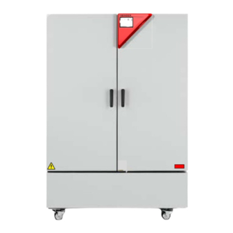
Page 22: Chamber Overview
Chamber overview Figure 4: Constant climate chamber KBF / KBF-UL / KMF size 240 Instrument box Door handle Outer door Refrigerating machine and humidity generation module 2.2 Instrument panel 5,7" controller display with touchscreen USB interface Pilot lamp Figure 5: Instrument panel with MB2 program controller and USB interface KBF / KBF-UL + KMF (E6) 09/2021 page 22/160... -
Page 23: Lateral Control Panels
Figure 6: Lateral control panels at the sides of the refrigerating / humidity generation module with optional equipment Main power switch DIN socket for additional Pt 100 sensor (available via BINDER INDIVIDUAL customized solutions) DIN socket for analog outputs (option) RS485 interface... -
Page 24: Rear View With Water Connections
Rear view with water connections (10) (11) (13) (14) Figure 7: Rear view of the chamber with water connections (10) Socket for optional freshwater can (chap. 19.9.1) (11) Power cable (12) not used (13) Freshwater connection “IN” with screw thread ¾’’ for hose ½“, with union nut (14) Wastewater connection “OUT”... -
Page 25: Completeness Of Delivery, Transportation, Storage, And Installation
Note on second-hand chambers (Ex-Demo-Units): Second-hand chambers are chambers that were used for a short time for tests or exhibitions. They are thoroughly tested before resale. BINDER ensures that the chamber is technically sound and will work flaw- lessly. Second-hand chambers are marked with a sticker on the chamber door. Please remove the sticker before commissioning the chamber. -
Page 26: Guidelines For Safe Lifting And Transportation
• If the steam humidifying system has NOT been emptied: +3 °C / 37.4 °F to +60 °C / 140 °F. • After BINDER Service has emptied the steam humidifying system: -10 °C / 14 °F to +60 °C / 140 °F. -
Page 27: Location Of Installation And Ambient Conditions
37.4 °F with filled steam humidifying system. Damage to the chamber. Contact BINDER Service before any storage below +3 °C / 37.4 °F. Permissible ambient humidity: max. 70 % r.h., non-condensing. After extensive operation at humidity levels > 70% r.h., condensation from excessive humidity can lead to corrosion during storage. - Page 28 Ambient conditions • Permissible ambient temperature range during operation: +18 °C / 64.4 °F to +32 °C / 89.6 °F. At ele- vated ambient temperature values, fluctuations in temperature can occur. The ambient temperature should not be substantially higher than the indicated ambient tem- perature of +22 °C +/- 3 °C / 71.6 °F +/- 5.4 °F to which the specified technical data relate.
-
Page 29: Installation And Connections
Installation and connections Spacer for wall distance Please fix both spacers with the supplied screws at the chamber rear. This serves to ensure the prescribed minimum distance to the rear wall of 100 mm / 3.94 in. Figure 8: Spacer for wall distance Figure 9: Chamber rear with mounted spacers Wastewater connection Fasten the wastewater hose to the wastewater connection “OUT”... -
Page 30: Freshwater Supply
1 µS/cm (ultrapure water), may cause acid corrosion due to its low pH). • Water treated by the optional water treatment system BINDER Pure Aqua Service (disposable system). A reusable measuring equipment to assess the water quality is included (chap. 19.10). -
Page 31: Manual Freshwater Supply Via External Freshwater Can (Option)
4.3.2 Manual freshwater supply via external freshwater can (option) If no house water connection with suitable water is available, you can manually supply water by filling a freshwater can (option, volume: 20 liters / 0.71 cu.ft. You can attach the freshwater can on the rear of the chamber or place it next to the chamber (chap. -
Page 32: Safety Kit: Hose Burst Protection Device With Reflux Protection Device (Available Via Binder Individual Customized Solutions)
4.3.4 Safety kit: Hose burst protection device with reflux protection device (available via BINDER INDIVIDUAL customized solutions) A safety kit with a reflux protection device is available for protection of the drinking water system, and against flooding caused by burst water hoses. - Page 33 Figure 11: Assembly of the safety kit (hose burst protection and reflux protection devices) Release of the reflux protection device: In case the hose burst protection device interrupts the water supply, first find the reason and remove it as necessary. Close the water tap. Release the valve by a half left-turn of the upper knurled part. You can hear the release of the valve as a clicking noise.
-
Page 34: Electrical Connection
• Only use original connection cables from BINDER according to the above specification. UL chambers: Use only a UL Listed Power supply cord (UL category ELBZ), SJT 3x14 AWG (2.08 mm²);... -
Page 35: Connection Of The Voltage Changer (Option For Kbf)
To completely separate the chamber from the power supply, you must disconnect the power plug. Install the chamber in a way that the power plug is easily accessible and can be easily pulled in case of danger. Remark when operating the chamber with a power frequency of 60 Hz: When connected to a power supply 1N~ with a frequency of 60 Hz, a leakage current of more than 3.5 mAmp is possible. - Page 36 Carrying handle Pilot lamp (green) Power switch Connection socket for KBF Power cable Figure 12: Voltage changer (front) To establish the electrical connection of the constant climate chamber with the voltage changer, proceed in the following order: 1. Connect the power cable of the constant climate chamber to the connection socket (D) of the voltage changer 2.
-
Page 37: Functional Overview Of The Mb2 Chamber Controller
You can enter values or programs directly at the controller or use the APT-COM™ 4 Multi Management Software (option) spe- cially developed by BINDER. Operating mode Temperature values... -
Page 38: Operating Functions In Normal Display
Operating functions in normal display Current operating mode Text list for information icons Date, time, authorization level of the logged-in user, memory Quick setpoint entry Continue to next screen Back to Normal display Information Program start Setpoint entry Event list Display of active alarms Access to main menu Figure 15: Operating functions of the MB2 controller in normal display (example values) -
Page 39: Display Views: Normal Display, Program Display, Chart-Recorder Display
Display views: Normal display, program display, chart-recorder display Press the Change view icon to toggle between normal display, program display and chart-re- corder display. Press the Normal display icon to return from program display and chart recorder display back to Normal display. -
Page 40: Controller Icons Overview
Controller icons overview Navigation icons in Normal display Icon Signification Function Access from Normal display to the main menu Main menu Alarm Access from Normal display to the list of active alarms Access from Normal display to the event list Event list Access from Normal display to the setpoint entry menu: set- Setpoint setting... - Page 41 Functional icons in the chart recorder display Icon Signification Function Show legend Show legend Hide legend Hide legend Switch between legend pages Switch legend Show indications Show indication “Door open” (B2) Hide indications Hide indication “Door open” (B2) Pause chart recorder and change to history display. Data recording History display continues.
-
Page 42: Operating Modes
Operating modes The MB2 program controller operates in the following operating modes: • Idle mode The controller is not functional, i.e., there is no heating or refrigeration and no humidification or dehu- midification. The fan is off. The chamber approximates ambient values. You can activate and deactivate this operating mode with the “Idle mode”... -
Page 43: Controller Menu Structure
Controller menu structure Use the navigation icons in the screen footer in Normal display to access the desired controller functions. The available functions depend on the current authorization level “Service”, “Admin” or “User” (chap. 13.1). This is selected either during login or can be available without password protection. Main menu: program settings, further information, “Service”... -
Page 44: Main Menu
• Access to service data, controller reset to factory settings (chap. 5.5.3) • Available only for users with “Service” and “Admin” authorization level. Full functional range only for BINDER Service (users with “Service” authorization level). “Programs” submenu • Access to the controller’s program functions (chap. 8, 9, 10) -
Page 45: Settings" Submenu
5.5.3 “Service” submenu The “Service” submenu is available for users with “Service” or “Admin” authorization level. When logged-in with “Admin” authorization level the user will find information to tell the BINDER Service in service case. Path: Main menu > Service Serial number of the chamber, setup version chap. -
Page 46: Principle Of Controller Entries
Principle of controller entries In the selection and entry menus there are icons displayed in the footers which you can use to take over the entry or cancel it. Selection menu (example) Entry menu (example) After completing the settings there are the following possibilities: Press the Confirm icon to take over the entries and exit the menu or continue the menu se- quence. -
Page 47: Performance When Opening The Door
To reduce odors quickly we recommend heating up the chamber to its nominal temperature for one day and in a well-ventilated location. WARNING: If customer should use a BINDER chamber running in non-supervised continu- ous operation, we strongly recommend in case of inclusion of irrecoverable specimen or samples to split such specimen or samples and store them in at least two chambers, if this is feasible. -
Page 48: Turning On/Off Humidity Control
Locked operation Provided that the user administration has been activated by the assignment of passwords for the different authorization types, the controller operation is first locked after turning on the unit, recognizable by the closed lock icon in the header. In the locked view the controller provides all display functions. -
Page 49: Set-Point Entry In "Fixed Value" Operating Mode
Set-point entry in “Fixed value” operating mode In Fixed value operating mode, you can enter a temperature set-point, a humidity set-point, the fan speed, and the switching-state of special controller functions. All settings made in Fixed value operating mode remain valid until the next manual change. They are saved also when turning off the chamber or in case of toggling to Idle Mode or Program Mode. -
Page 50: Set-Point Entry For Temperature, Humidity, And Fan Speed Through The "Setpoints" Menu
Set-point entry for temperature, humidity, and fan speed through the “Set- points” menu Press the Setpoint setting icon to access the “Setpoints” setting menu from Normal display. “Setpoints” menu. Select “Fixed value operation setpoints” to access the individual parameters. • Select the field “Temperature” and enter the desired temperature setpoint. KBF / KBF-UL setting range: -5 °C up to 70 °C, KMF setting range: -15 °C up to 100 °C. -
Page 51: Direct Setpoint Entry For Temperature And Humidity Via Normal Display
Direct setpoint entry for temperature and humidity via Normal display Alternatively you can also enter the setpoints directly via Normal display. Normal display. Select the setpoint you want Example: “Temperature” entry menu. Enter the to change. desired setpoint and confirm entry with Confirm icon. -
Page 52: Timer Program: Stopwatch Function
The operation lines count from right to left. Example: Activated operation line “Humidity off” = 000000000000000 Deactivated operation line “Humidity off” = 000000000000000 Timer program: stopwatch function During an entered duration the controller constantly equilibrates to the setpoints entered in Fixed value operation mode (temperature, humidity, fan speed, configuration of the operation lines). -
Page 53: Stopping A Running Timer Program
Stopping a running timer program 8.2.1 Pausing a running timer program Press the Program pause icon to interrupt the program. The program is paused. The program runtime stops running down, the time display flashes. There are the following options: Press the Program start icon to continue the program Press the Cancelling icon to cancel the program 8.2.2 Cancelling a running timer program Press the Program cancelling icon to cancel the program. -
Page 54: Time Programs
Time programs The MB2 program controller permits programming time programs with real-time reference. It offers 25 pro- gram memory positions with up to 100 program sections each. For each program section you can enter a temperature set-point, a humidity set-point, the fan speed, sec- tion duration, type of temperature and humidity transition (ramp or step) and the tolerance range. -
Page 55: Performance During Program Delay Time
9.1.1 Performance during program delay time During the configured program delay time until program start, the controller equilibrates to the current set- points of Fixed value operation mode. Modifications of these setpoints are effective. When the configured moment for program start is reached, the program delay time ends and the program starts running. Stopping a running time program 9.2.1 Pausing a running time program Press the Program pause icon to interrupt the program. -
Page 56: Creating A New Time Program
Creating a new time program Path: Main menu > Programs > Time program “Time program” menu: Enter the program name and, if desired, addi- overview of the existing programs. tional program information in the corresponding fields. Select an empty program place. Press the Confirm icon. -
Page 57: Deleting A Time Program
Program editor: “Edit program” menu Select the desired function and press the Confirm icon. The program editor offers following options: • Change the program name • Copy program • Replace program: Replacing an new or an existing program with the copied program. This menu point is visible only after a program has been copied. -
Page 58: Section Editor: Section Management
Section editor: section management Path: Main menu > Programs > Time program Select the desired program. Program view. Section view (example: section 1). Select the desired program section There are the following options: (example: section 1) Select a parameter to enter or modify the according value (chap. -
Page 59: Add A New Program Section
9.6.1 Add a new program section Section editor: “Edit section” menu. Select “Create new section” and press the Con- firm icon. Then select whether to insert the new section be- fore or after the current section. Press the Confirm icon. The new section opens. 9.6.2 Copy and insert or replace a program section Program view. -
Page 60: Deleting A Program Section
Press the Edit icon to open the section editor if you want the current section to be replaced or the copied section to be inserted before or after it Program view. Section view (example: section 1). Select the section to be replaced or before or Press the Edit icon to open the section editor after which the copied section shall be in- serted (example: section 2) and press the... -
Page 61: Value Entry For A Program Section
Value entry for a program section Path: Main menu > Programs > Time program Select the desired program and section. The section view gives access to all parameters of a program section. You can enter or modify the values. Program name and section number Section duration Type of setpoint transition: ramp or step Operation lines... -
Page 62: Set-Point Ramp And Set-Point Step
9.7.2 Set-point ramp and set-point step You can define the type of temperature and humidity transitions for each individual program section. “Ramp” mode: Gradual changes of temperature and humidity The set-point of a given program section functions as the section’s start temperature. During the section’s duration, the set-point gradually passes to the set-point of the subsequent program section. -
Page 63: Special Controller Functions Via Operation Lines
“Ramp” and “Step” mode example (representation of a temperature course) W/°C t/min. Corresponding program table Duration Temperature Humidity Section No. Ramp or Step [hh:mm:ss] [°C] [% rH] 00:10:00 40.0 xxxx xxxx Step 00:20:00 60.0 xxxx xxxx Step 00:10:00 80.0 xxxx xxxx Step 00:20:00... -
Page 64: Setpoint Entry
Section view indicating the operation lines. Activated operation line: switching status “1” (On) Deactivated operation line: switching status “0” (Off) The operation lines count from right to left. Example: Activated operation line “Humidity off” = 000000000000000 Deactivated operation line “Humidity off” = 000000000000000 9.7.4 Setpoint entry •... -
Page 65: Repeating One Or Several Sections Within A Time Program
Section view, showing the temperature tolerance band • Select the field “Tolerance band min” and enter the desired lower tolerance band value. Setting range: -99999 to 99999. Confirm entry with Confirm icon. The controller returns to the section view. • Select the field “Tolerance band max” and enter the desired upper tolerance band value. Setting range: -99999 to 99999. -
Page 66: Saving The Time Program
9.7.7 Saving the time program Section view. Program view. After the all desired values of the program Press the Confirm icon to take over the pro- section have been configured, press the Con- gramming. firm icon to take over the programming. The controller changes to the Normal display. -
Page 67: Week Programs
Week programs The MB2 program controller permits programming week programs with real-time reference. It offers 5 week program places in total with up to 100 shift points for each week program. Path: Main menu > Programs> Week program 10.1 Starting an existing week program In Normal display press the Program start icon to access the “Program start”... -
Page 68: Creating A New Week Program
10.3 Creating a new week program Path: Main menu > Programs > Week program Enter the program name and, if desired, addi- “Week program” menu: tional program information in the correspond- overview of the existing programs. ing fields. Select an empty program place. Select the set-point course “Ramp”... -
Page 69: Program Editor: Program Management
10.4 Program editor: program management Path: Main menu > Programs > Week program “Week program” menu: Program view (example: program 1). overview of the existing programs. If a new program has been created, there is Select an existing program (example: pro- just one program section. -
Page 70: Deleting A Week Program
To add a new section, select “Create new Program view. section” and press the Confirm icon. With a new section no weekday is specified. There- The program view opens. fore, the section is first marked in red and cannot be saved. -
Page 71: Section Editor: Section Management
10.5 Section editor: section management Path: Main menu > Programs > Week program Select the desired program. Program view. Section view (example: section 1). Select the desired program section There are the following options: (example: section 1) ... -
Page 72: Add A New Program Section
10.5.1 Add a new program section Section editor: “Edit section” menu. Program view. With a new section no weekday is specified. There- Select “Create new section” and press the fore, the section is first marked in red and cannot be Confirm icon. -
Page 73: Deleting A Program Section
Select “Replace section” to replace the selected sec- tion with the copied section Select “Insert section” to additionally add the copied section. Press the Confirm icon. If you selected “Insert section” the sections are auto- matically arranged in the correct chronological order. Section editor: “Edit section”... -
Page 74: Weekday
“Change program name” menu. In the field “Course” select the desired setting “Ramp” or “Step” and press the Confirm icon. 10.6.2 Weekday In the field “Weekday” select the desired weekday. With “Daily” selected, this section will run every day Section view. at the same time. -
Page 75: Setpoint Entry
10.6.4 Setpoint entry • Select the field “Temperature” and enter the desired temperature setpoint. KBF / KBF-UL setting range: -5 °C up to 70 °C, KMF setting range: -15 °C up to 100 °C. Confirm entry with Confirm icon. The controller returns to the section view. •... -
Page 76: Notification And Alarm Functions
Notification and alarm functions 11.1 Notification and alarm messages overview 11.1.1 Notifications Notifications are indicated by information icons displayed in the screen header in Normal display An information icon serves as an indication of a certain condition. If this condition persists, in some cases an alarm will be triggered after a fix or configurable interval. As long as the condition persists, the information icon therefore continues to be displayed also in state of alarm. -
Page 77: Alarm Messages
11.1.3 Messages concerning the humidity system Start after condition Condition and measures Message occurred The humidity module is defective. Contact BINDER ser- “Humidity system” immediately vice The humidity module cannot fill up. In case of freshwater supply via water pipe: The water tap is closed, or the chamber is defective (e.g. -
Page 78: State Of Alarm
When operating the chamber without water connection, turn off humidity control in the “set- points” menu (chap. 6.3) in order to avoid humidity alarms. 11.2 State of alarm 1. Visual indications in Normal display: alarm message, screen header flashing in red color 2. -
Page 79: Tolerance Range Settings
Pressing the Reset alarm icon mutes the buzzer for all active alarms. The icon then disappears. • Acknowledging while the alarm condition persists: Only the buzzer turns off. The visual alarm indication remains on the controller display. The alarm remains in the list of active alarms. When the alarm condition has ended, the visual alarm indication is automatically cleared. -
Page 80: Activating / Deactivating The Audible Alarm (Alarm Buzzer)
The user cannot restart the device again. The protective cut-off device is located internally. Only a service specialist can replace it. Therefore, please contact an authorized service provider or BINDER Service. 12.2 Overtemperature safety controller class 3.1 The chambers are regularly equipped with an electronic overtemperature safety controller (temperature safety device class 3.1 according to DIN 12880:2007). -
Page 81: Safety Controller Modes
12.2.1 Safety controller modes You can select between “Limit (absolute)” and “Offset (relative)” safety controller mode • Limit: Absolute maximum permitted temperature value This setting offers high safety as a defined temperature limit will not be exceeded. It is important to adapt the safety controller set-point after each modification of the temperature set-point. -
Page 82: Message And Measures In The State Of Alarm
Regularly check the safety controller setting for set-point type “Limit” or “Offset” • in Fixed value operating mode according to the entered set-point temperature value • in program mode according to the highest temperature value of the selected temperature program Set the safety controller set-point by approx. -
Page 83: Temperature Safety Device Class 3.3 (Option)
12.3 Temperature safety device class 3.3 (option) With the option over/under temperature protective device (temperature safety device class 3.3 acc. to DIN 12880:2007) the chamber is equipped with two additional safety devices (class 3.1 and class 3.2). The combination of the safety devices is regarded as a safety device class 3.3. The temperature safety device, class 3.3, serves to protect the constant climate chamber, its environment and the contents from exceeding the maximum permissible temperature. -
Page 84: Temperature Safety Device Class 3.1
12.3.1 Temperature safety device class 3.1 If you turn the control knob (8) to its end-stop (position 10), the safety de- (8a) vice class 3.1 protects the appliance. If you set the temperature a little above the set-point, it protects the loading material. If the safety device class 3.1 has taken over control, identifiable by the red alarm lamp (8a) lighting up, the message “Temp. -
Page 85: Temperature Safety Device Class 3.2
12.3.2 Temperature safety device class 3.2 The safety device class 3.2 is equivalently set to a minimum temperature (9a) the chamber will not fall below. This protection against prohibited low tem- peratures can, for example, serve to protect sensitive cultures from cooling down too much. -
Page 86: User Management
• All passwords can be changed in the “log out” submenu (chap. 13.3). “Service” authorization level • Authorization level only for BINDER service • Extensive authorization for controller operation and configuration, access to service data • The passwords for “Service”, “Admin” and “User” authorization levels can be changed in the “log out”... - Page 87 Operation after user login At user login, the authorization level is selected and confirmed by entering the respective pass- word. Following user login, controller operation is available, recognizable by the open-lock icon in the header. The available controller functions correspond to the user’s authorization level. Password protection activated for all levels: operation without user login is locked If passwords have been assigned for all authori- zation levels, the controller is locked without reg-...
- Page 88 Information window To check the authorization level of the user currently logged-in, select in Normal display the arrow far right in the display header. The information window shows date and time, the controller’s free memory space and under “Authorization” the authorization level of the current user. If passwords have been assigned for all authorization levels, a user without login (password entry) has no authorization.
-
Page 89: Log In
13.2 Log in Path: Main menu > User > Log in Controller with- out a user logged-in Selection of user type (example) All selection possibilities are password protected Controller with logged-in user After completing the settings, press the Confirm icon to take over the entries and exit the menu, or press the Close icon to exit the menu without taking over the entries. -
Page 90: Log Out
13.3 Log out Path: Main menu > User > Log out User logoff with “Admin” authorization Controller Controller with without a user logged-in user logged-in User logoff with “User” authorization Controller Controller with without a user logged-in user logged-in 13.4 User change If the password function has been deactivated (chap.13.5.2) this function is not available. -
Page 91: Password Assignment And Password Change
User selection (example) All selection possibilities are password protected Controller with logged- in user 13.5 Password assignment and password change This function is not available for a user logged-in with “User” authorization. 13.5.1 Password change A logged-in user can change the passwords of his current level and of the next lower level(s). Example: A user with “Admin”... - Page 92 Selection of the authorization level Enter desired password. If desired, press the Change (example: view with “Admin” authorization) keyboard icon to access other entry windows. In the “Keyboard switch” window you can select different keyboards to enter uppercase and lowercase letters, digits, and special characters.
-
Page 93: Deleting The Password For An Individual Authorization Level
13.5.2 Deleting the password for an individual authorization level A user logged-in with “Service” or “Admin” authorization can delete the passwords of his current level and of the next lower level(s). To do this no password is entered during a password change. Path: Main menu >... -
Page 94: New Password Assignment For "Service" Or "Admin" Authorization Level When The Password Function Was Deactivated
13.5.3 New password assignment for “service” or “admin” authorization level when the password function was deactivated If the password protection for an authorization level has been deactivated, i.e., no password is assigned, no login for this level is possible. Therefore, access to this authorization level is available without login. If the password for the “Service”... -
Page 95: Activation Code
13.6 Activation code Certain functions of the controller can be unlocked with a previously generated activation code. The activation code enables access to functions available only in the “Service” authorization level by users without a “Service” authorization. Such functions include e.g., adjustment or extended configurations. The activation code is available in authorization levels. -
Page 96: General Controller Settings
General controller settings Most of the general settings can be accessed in the “Settings” submenu, which is available for users with “Service” or “Admin” authorization level. It serves to enter date and time, select the language for the con- troller menus and the desired temperature unit and to configure the controller’s communication functions. 14.1 Selecting the controller’s menu language The MB2 program controller communicates by a menu guide using real words in German, English, French, Spanish, and Italian. - Page 97 Or later: Path: Main menu > Settings > Date and time “Date and time” submenu. “Date / time” entry menu. Select the field “Date / time”. Enter date and time and press the Confirm icon. “Date and time” submenu. “Date and time” submenu. In the field “Daylight saving time switch”...
-
Page 98: Selecting The Temperature Unit
14.3 Selecting the temperature unit Following start-up of the chamber: Or later: Path: Main menu > Settings > Chamber Select the desired temperature unit and press the Confirm icon. Change of the temperature unit between °C and °F. If the unit is changed, all values are converted accordingly C = degree Celsius 0 °C = 31°F... -
Page 99: Touchscreen Calibration
• Select the field “Brightness”. Move the grey slide to the left or right to define the brightness of the display • left = darker (minimum value: 0) • right = brighter (maximum value: 100) Press the Confirm icon. • Select the field “Wait time for screen saver” and enter the desired waiting time for the screen saver in seconds. -
Page 100: Network And Communication
14.5 Network and communication For these settings at least the “Admin” authorization level is required. 14.5.1 Serial interfaces The chamber is optionally equipped with a serial RS485 interface. This menu allows to configure the communication parameters of the RS485 interface. The device address is required to recognize chambers with this interface type in a network, e.g. -
Page 101: Ethernet
14.5.2 Ethernet 14.5.2.1 Configuration Path: Main menu > Settings > Ethernet “Ethernet” submenu. • In the field “IP address assignment” select the desired setting “Automatic (DHCP)” or “Man- ual”. With selection “Manual” you can enter the IP- address, the subnet mask and the standard gateway manually. -
Page 102: Web Server
Internet. The IP address is available via Chamber information > Ethernet. The BINDER web server opens. Enter the user name and password which have been assigned for the web server in the controller menu. This enables online access to the controller display, to see e.g., the event list or error messages. In this view no settings can be changed. -
Page 103: E-Mail
14.5.4 E-Mail As soon as an alarm was triggered, an e-mail is sent to the configured e-mail address. Path: Main menu > Settings > Email E-mail address entry: “Email” submenu. Select the desired e-mail address field and enter the e-mail address. You can use the Keyboard change icon for entry. -
Page 104: Usb Menu: Data Transfer Via Usb Interface
14.6 USB menu: Data transfer via USB interface The USB port is located in the instrument box. When you insert a USB-stick, the “USB” menu opens. The USB stick must be formatted with FAT32 and have at least 8GB of memory. Depending on the user’s authorization level, different functions (highlighted in black) are available for the logged-in user. -
Page 105: General Information
General information 15.1 Service contact page Path: Main menu > Contact 15.2 Current operating parameters Press the Information icon to access the “Info” menu from Normal display. “Info” menu. Select the desired information. • Select “Program operation” to see information on a currently running program. •... -
Page 106: Event List
(chap. 16.2) the Event list is cleared. 15.4 Technical chamber information Path: Main menu > Device info Chamber name and setup Versions of CPU, I/O module and safety for BINDER controller Service Information on digital and analog inputs for BINDER and outputs and phase angle outputs... -
Page 107: Self-Test Function
The results of the self-test are stored in the service recorder of the controller. You can export them using the controller’s USB interface and send them to BINDER Service (use function “Export service data” to USB stick, chap. 14.6). BINDER Service will evaluate the data using an analyzing tool. - Page 108 Alarm message “Self-test active”. “Active alarms” menu. The self-test program is running. The indicated The zero-voltage relay alarm output is not acti- set-points are non-functional. vated with the alarm message “Self-test active”. With enabled buzzer: the buzzer sounds. Press the Reset alarm icon to mute the buzzer. Press the Alarm icon to access the “Active alarms”...
-
Page 109: Chart Recorder Display
Chart recorder display This view offers graphic representation of the measurement course. Data representation imitates a chart recorder and allows recalling any set of measured data at any point of time taken from the recorded period. 16.1 Views Press the Change view icon to access the pen recorder display. 16.1.1 Show and hide legend Show legend Hide legend... -
Page 110: Show And Hide Specific Indications
16.1.3 Show and hide specific indications Show indications Hide indications Press the Show indications icon to display the indication “Door open” (B2). Indication “Door open” displayed. 16.1.4 History display History display Press the History display icon to change to the history display. History display. - Page 111 History display: Curve selection Curve selection Press the Curve selection icon to access the “Curve selection” submenu. “Curve selection” submenu. Select the curves to be displayed by checking the checkbox of the corresponding parameter. Press the Confirm icon History display: Search the required instant Search Press the Search icon to access the “Search”...
- Page 112 History display: Zoom function Zoom Press the Zoom icon to access the “Zoom” submenu. “Zoom” submenu. Select the zoom factor and press the Confirm icon History display: Show and hide scroll buttons to scroll to an instant Show scroll buttons Hide scroll buttons Press the Show scroll buttons icon to access the “Page selection”...
-
Page 113: Setting The Parameters
16.2 Setting the parameters This menu allows setting the storage interval, the type of values to be shown and the scaling of the tem- perature and humidity charts. Path: Main menu > Settings > Measurement chart “Measurement chart” submenu. • Select the field “Storage interval” and enter the desired storage interval. Confirm entry with Confirm icon. -
Page 114: Humidification / Dehumidification System
Humidification / dehumidification system The chamber is equipped with a capacitive humidity sensor. This results in a control accuracy of up to +/- 3 % r.h. of the set point. The temperature-humidity diagrams (Figure 19) show the possible working ranges for humidity. - Page 115 Heat emission of electrical devices connected inside the chamber may modify the tempera- ture and humidity range. The chambers are equipped with a door heating system to prevent condensation in the door area. If the set points for temperature or humidity are outside the optimum range, condensation can arise in the door area.
-
Page 116: Function Of The Humidifying And Dehumidifying System
• Water intake temperature NOT below +5 °C / 41 °F and not exceeding 40 °C / 104 °F. BINDER GmbH is NOT responsible for the water quality provided by the customer. Any problems and malfunctions that might arise following use of water of deviating quality is excluded from liability by BINDER GmbH. -
Page 117: Defrosting At Refrigerating Operation
Defrosting at refrigerating operation BINDER constant climate chambers are very diffusion-proof. To ensure high temperature precision there is no automatic cyclic defrosting device. The DCT™ refrigerating system largely avoids icing of the evapo- ration plates. However, at very low temperatures the moisture in the air can condense on the evaporator plates leading to icing. -
Page 118: Options
APT-COM™ 4 Basic Edition is included with the chamber. APT-COM™ 4 is available for download on the BINDER website. Upon registering the chamber, you will receive a license key with which you can activate the functionality of the Basic Edition for your downloaded version. -
Page 119: Data Logger Kits (Option)
BINDER Data Loggers are equipped with a keyboard and a large LCD display, alarm functions and a real- time function. Measurement data are recorded in the Data Logger and can be read out after the measure- ment via the RS232 interface of the Data Logger. -
Page 120: Zero-Voltage Relay Alarm Outputs For Temperature And Humidity (Option)
19.5 Zero-voltage relay alarm outputs for temperature and humidity (option) The chamber equipment with optional zero-voltage relay outputs for temperature and humidity (option) permits the transmission of alarms to a central monitoring system. Connection is established via a DIN socket (6) located on the right lateral control panel. Figure 21: Pin configuration of the DIN socket (6) Temperature contact Humidity contact... -
Page 121: Object Temperature Display With Flexible Pt 100 Temperature Sensor (Option)
(sample values) The object temperature data are put out together with the data of the temperature controller and can be documented by the APT-COM™ 4 Multi Management Software (option, chap. 19.1) developed by BINDER. Technical data of the Pt100 sensor: •... -
Page 122: Mounting The Freshwater Can
19.7.1 Mounting the freshwater can Fixing (if required) Hang the can with its holding device on its 4 carriers. You can install it either at the left or the right side. Cable connection (15) Freshwater hose connection (16) Figure 23: Freshwater can (option) Cable connections Connect the plug of the cable to the socket (10) at the rear of the chamber. -
Page 123: Mounting The Wastewater Can
Hose connections Plug the freshwater hose into the hose connection (16) above the freshwater can and secure it with a hose clamp. You can use a part of the standard supplied water hose. Screw the hose nozzle (brass) to the free edge of the hose and screw it directly onto the freshwater connection “IN”... -
Page 124: Mounting With Wastewater Recycling
In case of soiling / contamination of the interior, conduct the wastewater to the wastewater connection or use the wastewater can. BINDER GmbH is NOT responsible for the water quality at the user’s site, especially when reusing wastewater. Any problems and malfunctions that might arise following use of wastewater are excluded from liability by BINDER GmbH. -
Page 125: Binder Pure Aqua Service (Option)
19.8 BINDER Pure Aqua Service (option) The optional BINDER water treatment system (disposable system) is available to treat tap water. The life- time depends on water quality and the amount of treated water used. The measuring equipment to assess the water quality is reusable. - Page 126 Do not use cleaning agents that may cause a hazard due to reaction with components of the device or the loading material. If there is doubt regarding the suitability of cleaning products, please contact BINDER service. We recommend using the neutral cleaning agent Art. No. 1002-0016 for a thorough cleaning.
-
Page 127: Decontamination / Chemical Disinfection
For chemical disinfection, we recommend using the disinfectant spray Art. No. 1002-0022. Any corrosive damage that may arise following use of other disinfectants is excluded from lia- bility by BINDER GmbH. With every decontamination / disinfection method, always use adequate personal safety con- trols. -
Page 128: Maintenance And Service, Troubleshooting, Repair, Testing
For personnel requirements please refer to the Service Manual. • Repair Repair of the chamber can be performed by BINDER Service or by BINDER qualified service partners or technicians, in accordance with the description in the Service Manual. After maintenance, the chamber must be tested prior to resuming operation. -
Page 129: Simple Troubleshooting
If there are is a technical fault or shortcoming, take the chamber out of operation and inform BINDER Service. If you are not sure whether there is a technical fault, proceed ac- cording to the following list. If you cannot clearly identify an error or there is a technical fault, please contact BINDER Service. - Page 130 (chap. 4.4). Chamber without function. Check chamber fuse and replace it Chamber fuse has responded. if appropriate. If it responds again, contact BINDER service. Controller defective. Nominal temperature exceeded Contact BINDER service. by 10° due to chamber failure. Over temperature protective de- vice (class 1) responds.
- Page 131 Humidity fluctuation, together with temperature fluctuation Select cooler place of installation > 1 °C with a set-point approx. Place of installation too hot. or contact BINDER service. 3 °C above ambient tempera- ture. Capillary tube blocked Contact BINDER service. Not enough refrigerant.
-
Page 132: Sending The Chamber Back To Binder Gmbh
21.4 Sending the chamber back to BINDER GmbH If you return a BINDER product to us for repair or any other reason, we will only accept the product upon presentation of an authorization number (RMA number) that has previously been issued to you. An au- thorization number will be issued after receiving your complaint either in writing or by telephone prior to your sending the BINDER product back to us. -
Page 133: Disposal
(Elektro- und Elektronikgerätegesetz, ElektroG from 20 October 2015, BGBl. I p. 1739) or contact BINDER service who will organize taking back and disposal of the cham- ber according to the German national law for electrical and electronic equipment (Elektro- und El- ektronikgerätegesetz, ElektroG from 20 October 2015, BGBl. -
Page 134: Disposal Of The Chamber In The Member States Of The Eu Except For The Federal Republic Of Germany
Elektronikgerätegesetz, ElektroG from 20 October 2015, BGBl. I p. 1739). Instruct BINDER Service to dispose of the device. The general terms of payment and delivery of BINDER GmbH apply, which were valid at the time of purchasing the cham- ber. - Page 135 If your distributor is not able to take back and dispose of the chamber, please contact BINDER service. Certified companies disassemble waste (used) BINDER equipment in primary substances for recycling according to Directive 2012/19/EU. The devices must be free from toxic, infectious or radioactive sub- stances in order to eliminate any health hazards to the employees of the recycling companies.
-
Page 136: Disposal Of The Chamber In Non-Member States Of The Eu
(certified since December 1996 by TÜV CERT). All test equipment used is subject to the administration of measurement and test equipment that is also a constituent part of the BINDER QM DIN EN ISO 9001 systems. They are controlled and calibrated to a DKD-Standard at regular intervals. -
Page 137: Kbf / Kbf-Ul Technical Data
Do NOT place samples outside this usable volume. Do NOT load this volume by more than half to enable sufficient airflow inside the chamber. Do NOT divide the usable volume into separate parts with large area samples. Do NOT place samples too close to each other in order to permit circulation between them and thus obtain a homogenous distribution of temperature and humidity. - Page 138 +22 °C +/- 3°C / 71.6 °F +/- 5.4 °F and a power supply voltage fluctuation of +/-10%. Technical data is determined in accordance to BINDER Factory Standard Part 2:2015 and DIN 12880:2007. All indications are average values, typical for chambers produced in series. We reserve the right to change technical specifications at any time.
-
Page 139: Kmf Technical Data
23.5 KMF technical data Chamber size Exterior dimensions Width, net mm / inch 880 / 34.65 925 / 36.42 1250 / 49.21 Height, gross (incl. feet/castors) mm / inch 1050 / 41.34 1460 / 57.48 1925 / 75.79 Depth, net mm / inch 650 / 25.59 800 / 31.50 890 / 35.04 Depth, gross (including door handle, I-triangle, con-... - Page 140 +22 °C +/- 3°C / 71.6 °F +/- 5.4 °F and a power supply voltage fluctuation of +/-10%. Technical data is determined in accordance to BINDER Factory Standard Part 2:2015 and DIN 12880:2007. All indications are average values, typical for chambers produced in series. We reserve the right to change technical specifications at any time.
-
Page 141: Equipment And Options (Extract)
Communication interface RS485 BINDER Data Logger kit for temperature / humidity: TH 70 for KBF / KBF-UL / TH 100 for KMF (chamber values) or TH 70/70 for KBF / KBF-UL / TH 100/70 for KMF (chamber and ambient values) External freshwater and wastewater cans (20 liters / 0.71 cu.ft. -
Page 142: Accessories And Spare Parts (Extract)
23.7 Accessories and spare parts (extract) BINDER GmbH is responsible for the safety features of the chamber only, provided skilled electricians or qualified personnel authorized by BINDER perform all maintenance and repair, and if components relating to chamber safety are replaced in the event of failure with original spare parts. -
Page 143: Dimensions Size 115
23.8 Dimensions size 115 [mm] KBF / KBF-UL + KMF (E6) 09/2021 page 143/160... -
Page 144: Dimensions Size 240
23.9 Dimensions size 240 [mm] KBF / KBF-UL + KMF (E6) 09/2021 page 144/160... -
Page 145: Dimensions Size 720
23.10 Dimensions size 720 [mm] KBF / KBF-UL + KMF (E6) 09/2021 page 145/160... -
Page 146: Dimensions Size 1020
23.11 Dimensions size 1020 [mm] KBF / KBF-UL + KMF (E6) 09/2021 page 146/160... -
Page 147: Certificates And Declarations Of Conformity
Certificates and declarations of conformity 24.1 EU Declaration of Conformity for KBF KBF / KBF-UL + KMF (E6) 09/2021 page 147/160... - Page 148 KBF / KBF-UL + KMF (E6) 09/2021 page 148/160...
- Page 149 KBF / KBF-UL + KMF (E6) 09/2021 page 149/160...
-
Page 150: Eu Declaration Of Conformity For Kmf
24.2 EU Declaration of Conformity for KMF KBF / KBF-UL + KMF (E6) 09/2021 page 150/160... - Page 151 KBF / KBF-UL + KMF (E6) 09/2021 page 151/160...
- Page 152 KBF / KBF-UL + KMF (E6) 09/2021 page 152/160...
-
Page 153: Certificate For The Gs Mark Of Conformity Of The "Deutsche Gesetzliche Unfallversicherung E.v." (German Social Accident Insurance) Dguv
24.3 Certificate for the GS mark of conformity of the “Deutsche Gesetzliche Unfallversicherung e.V.” (German Social Accident Insurance) DGUV KBF / KBF-UL + KMF (E6) 09/2021 page 153/160... - Page 154 KBF / KBF-UL + KMF (E6) 09/2021 page 154/160...
-
Page 155: Contamination Clearance Certificate
Contamination clearance certificate 25.1 For chambers located outside USA and Canada Declaration regarding safety and health Erklärung zur Sicherheit und gesundheitlichen Unbedenklichkeit The German Ordinance on Hazardous Substances (GefStofV), and the regulations regarding safety at the workplace, require that this form be filled out for all products that are returned to us, so that the safety and the health of our employees can be guaranteed Die Sicherheit und Gesundheit unserer Mitarbeiter, die Gefahrstoffverordnung GefStofV und die Vorschriften zur Si- cherheit am Arbeitsplatz machen es erforderlich, dass dieses Formblatt für alle Produkte, die an uns zurückgeschickt... - Page 156 Kind of transport / transporter / Transportweg/Spediteur: Transport by (means and name of transport company, etc.) Versendung durch (Name Spediteur o.ä.) ___________________________________________________________________________________ Date of dispatch to BINDER GmbH / Tag der Absendung an BINDER GmbH ___________________________________________________________________________________ KBF / KBF-UL + KMF (E6) 09/2021 page 156/160...
- Page 157 We hereby commit ourselves and guarantee that we will indemnify BINDER GmbH for all damages that are a consequence of incomplete or incorrect information provided by us, and that we will exempt BINDER GmbH from eventual damage claims by third parties./ Wir versichern, dass wir gegenüber BINDER für jeden...
-
Page 158: For Chambers Located In Usa And Canada
Please complete this form and the Customer Decontamination Declaration (next 2 pages) and attach the required pictures. E-mail to: IDL_SalesOrderProcessing_USA@binder-world.com After we have received and reviewed the complete information we will decide on the issue of a RMA num- ber. Please be aware that size specifications, voltage specifications as well as performance specifications are available on the internet at www.binder-world.us... - Page 159 Customer (End User) Decontamination Declaration Health and Hazard Safety declaration To protect the health of our employees and the safety at the workplace, we require that this form is com- pleted by the user for all products and parts that are returned to us. (Distributors or Service Organizations cannot sign this form) NO RMA number will be issued without a completed form.
- Page 160 4.5 Shipping laws and regulations have not been violated. I hereby commit and guarantee that we will indemnify BINDER Inc. for all damages that are a con- sequence of incomplete or incorrect information provided by us, and that we will indemnify and hold harmless BINDER Inc.
Need help?
Do you have a question about the KMF Series and is the answer not in the manual?
Questions and answers