Table of Contents
Advertisement
Quick Links
Advertisement
Table of Contents

Subscribe to Our Youtube Channel
Related Manuals for EXFO FIP-500

Summary of Contents for EXFO FIP-500
- Page 1 FIP-500 Fiber Inspection Scope www.EXFO.com...
- Page 2 Copyright © 2021 EXFO Inc. All rights reserved. No part of this publication may be reproduced, stored in a retrieval system or transmitted in any form, be it electronically, mechanically, or by any other means such as photocopying, recording or otherwise, without the prior written permission of EXFO Inc.
-
Page 3: Table Of Contents
Contents Contents Regulatory Information ......................v 1 Introducing the FIP-500 Fiber Inspection Scope ......... 1 Main Features .........................1 LED Indicators Description ......................4 Battery Status Icon Description ....................6 Power Sources ........................7 Available Options ........................8 Technical Specifications ......................8 Conventions ..........................9 2 Safety Information ..................11 General Safety Information ....................11... - Page 4 Contents 6 Working with the EXFO Basecamp Application ........45 Installing the EXFO Basecamp application on Your Smart Device .........46 Establishing or Closing a Connection With a Smart Device Via the Bluetooth Technology ..47 Enabling or Disabling the Wireless Communication ..............49 Working With a Wireless Network ..................50...
-
Page 5: Regulatory Information
Electronic test and measurement equipment is exempt from FCC part 15, subpart B compliance in the United States of America and from ICES-003 compliance in Canada. However, EXFO Inc. makes reasonable efforts to ensure compliance to the applicable standards. The limits set by these standards are designed to provide reasonable protection against harmful interference when the equipment is operated in a commercial environment. - Page 6 Your unit comes with an internal wireless module (adapter) and two antennas for which the information hereafter applies: This product does not contain any wireless user-serviceable components. Any unauthorized product changes or modifications will invalidate warranty and all applicable regulatory certifications and approvals. FIP-500...
- Page 7 Regulatory Information Canada and USA Wireless Compliance Related Information Your unit comes with an internal wireless module (adapter) and two antennas for which the information hereafter applies: This device complies with Part 15 of the FCC Rules. This device complies with Innovation, Sciences and Economic ...
- Page 8 : Channels 1 through 11 - Between the frequencies 2412 MHz - 2462 MHz. The output power is 11.7 dBm typical. Wi-Fi: Channels 1 through 11 - Between the frequencies 2412 MHz - 2462 MHz. The maximum output power is 18.5 dBm. viii FIP-500...
- Page 9 Regulatory Information European Wireless Compliance Related Information ® Your unit is designed to operate in the Bluetooth and WLAN 2.4 GHz bands. ® The information about the Bluetooth and Wi-Fi frequency bands is as follows: ® Bluetooth : Channels 1 through 13 - Between the frequencies ...
- Page 10 European Declaration of Conformity Hereby, EXFO declares that the radio equipment type “Wideband Data Transmission” is in compliance with European Directive 2014/53/EU. The full text of the EU declaration of conformity is available at the following Internet address: www.exfo.com/en/resources/legal-documentation.
- Page 11 Regulatory Information Japan Wireless Compliance Related Information ® Your unit is designed to operate in the Bluetooth and WLAN 2.4 GHz bands. ® The information about the Bluetooth and Wi-Fi frequency bands is as follows: ® Bluetooth : Channels 1 through 13 - Between the frequencies ...
-
Page 13: Introducing The Fip-500 Fiber Inspection Scope
Unless otherwise specified, the information applies both to the Android- and iOS-based smart devices. Note: Both on your unit and in the EXFO Basecamp application, the period is used as the decimal separator in numerical values, when applicable. - Page 14 Introducing the FIP-500 Fiber Inspection Scope Main Features AUTION The optical head of your unit contains precision components. To ensure optimum protection when you do not use the unit or during transportation, cover the optical head with the provided protective cap.
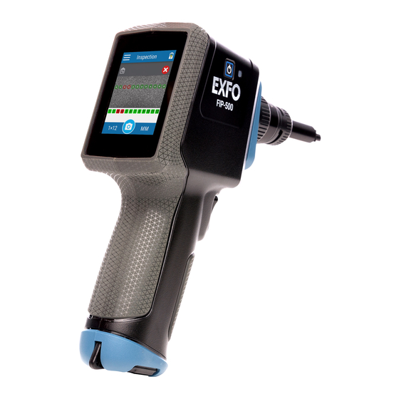
- Page 15 Introducing the FIP-500 Fiber Inspection Scope Main Features Back view LCD screen Bottom view USB 2.0 Type-C connector for battery charging (see Power Sources on page 7) Fiber Inspection Scope...
-
Page 16: Led Indicators Description
Introducing the FIP-500 Fiber Inspection Scope LED Indicators Description LED Indicators Description Your unit is equipped with a battery LED and a dual-function LED. Battery LED The battery LED, located next to the power button, on the side of your unit, provides you with information about the battery status. - Page 17 Introducing the FIP-500 Fiber Inspection Scope LED Indicators Description Dual-Function LED The dual-function LED is located just above the trigger used for captures, on the front of your unit. It can indicate the status of the inspection or be used as a flashlight to help you see the connectors you have to inspect in darker rooms (see Enabling or Disabling the Flashlight on page 44).
-
Page 18: Battery Status Icon Description
Introducing the FIP-500 Fiber Inspection Scope Battery Status Icon Description Battery Status Icon Description The battery status icon is shown in the upper right corner of the title bar. It complements the information provided by the unit’s LED. Icon Meaning The portion of the icon that appears in white in the title bar (in gray here) reflects the current battery level. -
Page 19: Power Sources
Introducing the FIP-500 Fiber Inspection Scope Power Sources Power Sources The Fiber Inspection Scope operates with the following power sources: Indoor use only: USB power adapter connected to a power outlet (fastest way to charge the battery). Note: The standard USB ports of a computer cannot power your unit or charge its battery while the unit is on. -
Page 20: Available Options
Introducing the FIP-500 Fiber Inspection Scope Available Options Available Options The MF option offered for your wireless FIP-500 Fiber Inspection Scope allows you to inspect multi-fiber connectors. Technical Specifications Hereby, EXFO declares that the radio equipment type “Wideband Data Transmission” is in compliance with European Directive 2014/53/EU. -
Page 21: Conventions
Introducing the FIP-500 Fiber Inspection Scope Conventions Conventions Before using the product described in this guide, you should understand the following conventions: ARNING Indicates a potentially hazardous situation which, if not avoided, could result in death or serious injury. Do not proceed unless you understand and meet the required conditions. -
Page 23: Safety Information
ARNING Use only accessories designed for your unit and approved by EXFO. For a complete list of accessories available for your unit, refer to its technical specifications or contact EXFO. - Page 24 General Safety Information MPORTANT Refer to the documentation provided by the manufacturers of any accessories used with your EXFO product. It may contain environmental and/or operating conditions limiting their use. MPORTANT When you see the following symbol on your unit...
-
Page 25: Other Safety Symbols On Your Unit
Safety Information Other Safety Symbols on Your Unit Other Safety Symbols on Your Unit One or more of the following symbols may also appear on your unit. Symbol Meaning Direct current Alternating current The unit is equipped with an earth (ground) terminal. The unit is equipped with a protective conductor terminal. -
Page 26: Electrical Safety Information
ES1 circuits only. Use only the listed and certified USB power adapter provided by EXFO with your unit. It provides reinforced insulation between primary and secondary, and is suitably rated for the country where the unit is sold. - Page 27 Safety Information Electrical Safety Information AUTION Position the unit so that the air can circulate freely around it. When you use the unit outdoors, ensure that it is protected from liquids, dust, direct sunlight, precipitation, and full wind pressure.
- Page 28 Measured in 0 °C to 31 °C (32 °F to 87.8 °F) range, decreasing linearly to 50 % at 40 °C (104 °F). Equipment must be normally protected against exposure to direct sunlight, precipitation and full wind pressure. Not exceeding ± 10 % of the nominal voltage. FIP-500...
-
Page 29: Getting Started With Your Unit
Turning on Your Unit When you turn on the unit for the very first time, you will be prompted to read and accept the EXFO license agreement and set the date and time (see the section about the first startup for more information). -
Page 30: Turning Off Your Unit
To exit the sleep mode and resume your work: Press the on/off button or press the trigger. To turn off the unit completely (shutdown): Press the on/off button for about three seconds. The unit will beep once and its LED will light up briefly. FIP-500... -
Page 31: Configuring Your Unit At First Startup
1. If it is not already done, turn on the unit (see Turning on Your Unit on page 17). 2. Read and accept the EXFO license agreement, then tap Next. 3. If necessary, configure the date and time by tapping anywhere on the corresponding line. -
Page 32: Understanding The Inspection Screen
To take a capture Note: You can also show or hide the overlay by tapping anywhere in the non-active area (gray background) of the image or directly on the image of the fiber when you view a specific fiber. FIP-500... -
Page 33: Changing Your Unit's Smarttip
Getting Started with Your Unit Changing Your Unit’s SmartTip Changing Your Unit’s SmartTip You can change the SmartTip of your unit to better suit your inspection needs. To change your unit’s SmartTip: 1. If necessary, remove the protective cap from the unit. 2. - Page 34 4. Align the new SmartTip with the optical head, and then slide it toward the unit until it stops. 5. Turn the SmartTip retaining screw clockwise (about a quarter turn) to secure the SmartTip in place. The new SmartTip is now ready to use. FIP-500...
-
Page 35: Cleaning And Connecting Optical Fibers
To ensure maximum power and to avoid erroneous readings: Always inspect fiber ends and make sure that they are clean as explained below before inserting them into the port. EXFO is not responsible for damage or errors caused by bad fiber cleaning or handling. - Page 36 EXFO uses good quality connectors in compliance with EIA-455-21A standards. To keep connectors clean and in good condition, EXFO strongly recommends inspecting them with a fiber inspection scope (or probe) before connecting them. Failure to do so may result in permanent damage to the connectors and degradation in measurements.
-
Page 37: Temperature Management
Getting Started with Your Unit Temperature Management Temperature Management The internal temperature of your unit will vary with the ambient temperature, but also with the type of tests you perform and their intensity. In high-temperature conditions, your unit will display warning messages. If the temperature keeps rising and reaches the limit, your unit will turn off as self-protection. -
Page 39: Setting Up Your Unit
Setting up Your Unit Adjusting Brightness You may want to adjust the display brightness yourself to better fit your work environment or preferences. You may also want to reduce the display brightness to save battery power (the higher the brightness level, the higher the power consumption). The brightness value is kept in memory even when you turn the unit off. -
Page 40: Adjusting The Date And Time
The new brightness value is taken into account immediately. Adjusting the Date and Time The date and time are expressed in international format. You can adjust them if necessary. To adjust the date or time manually: 1. From the main menu, tap Settings. FIP-500... - Page 41 Setting up Your Unit Adjusting the Date and Time 2. Scroll down to the Unit settings section. 3. Tap Date and time. 4. Tap the entry corresponding to the element that you want to modify. 5. Modify the settings according to your needs, and then tap to go back to the Date and time screen.
-
Page 42: Configuring Sleep Mode
The unit will not enter sleep mode while you perform tests. To configure the duration after which the unit enters sleep mode: 1. From the main menu, tap Settings. 2. Scroll down to the Unit settings section. FIP-500... - Page 43 Setting up Your Unit Configuring Sleep Mode 3. Tap Sleep. 4. Select the desired number of minutes, and then tap to go back to the Date and time screen. The new value is taken into account immediately. Fiber Inspection Scope...
-
Page 44: Reverting To Factory Settings
This operation does not affect the current date and time. To revert values to factory settings: 1. From the main menu, tap Settings. 2. Scroll down to the Unit settings section. FIP-500... - Page 45 Setting up Your Unit Reverting to Factory Settings 3. Tap Reset options. 4. Tap Factory settings. 5. Tap RESET to confirm your choice and start the operation. Fiber Inspection Scope...
-
Page 47: Inspecting Fiber Ends
ARNING Never look directly into a live fiber. It could cause serious eye damage. Always use your FIP-500 Fiber Inspection Scope. Selecting a Connector Type Once its initialization is complete, the unit displays the Inspection screen from which you can select the connector type (single- or multi-fiber) for the next capture. - Page 48 Inspecting Fiber Ends Selecting a Connector Type To select a connector type: 1. From the Inspection view, tap the numbers corresponding to the fiber arrangement. 2. In the Connector type window, select the type of connector you want to use. FIP-500...
- Page 49 Inspecting Fiber Ends Selecting a Connector Type 3. If you work with multi-fiber connectors, proceed as follows. 3a. Select the fiber arrangement corresponding to the connector you want to inspect. 3b. Select the key orientation of the connector. The new settings will be taken into account for the next inspection. Fiber Inspection Scope...
-
Page 50: Selecting A Fiber Type
Modal bandwidth: 3500-4700 MHz·km. Laser optimized (VCSEL) at 850 nm. Fiber channel designation: M5F. Fiber jacket is aqua or violet. Multimode OM5 50 µm Modal bandwidth: 3500-4700 MHz·km. Wideband multimode from 850-953 nm. Fiber jacket is violet or lime green. FIP-500... - Page 51 Inspecting Fiber Ends Selecting a Fiber Type To select the fiber type: 1. From the Inspection view, tap the fiber type. 2. In the Fiber type window, select the desired type of fiber. If you are not sure whether your setup uses singlemode or multimode fiber, you can have a look at the color chart displayed on the screen.
-
Page 52: Inspecting Multi-Fiber Ends
Pull the trigger located on the handle of the unit. The inspection results are displayed on screen. For more information on navigation through captures, see Navigating Through Multi-Fiber Captures on page 41. For more information on the overlay, see Displaying or Hiding the Overlay on page 43. FIP-500... -
Page 53: Navigating Through Multi-Fiber Captures
Inspecting Fiber Ends Navigating Through Multi-Fiber Captures Navigating Through Multi-Fiber Captures When you inspect multi-fiber connectors, once the analysis is complete, the application displays a global view of the connector (where several fibers are visible at a time). It allows you to have an overview of the inspection results as well as a way to localize any debris that could be located outside the perimeter of the fibers themselves. - Page 54 The icon and color in the background indicates the global status of the connector. Number of the displayed fiber (multi-fiber connector). The background color indicates the status of the inspection for this fiber. To access the global view of the connector FIP-500...
-
Page 55: Displaying Or Hiding The Overlay
Inspecting Fiber Ends Displaying or Hiding the Overlay Displaying or Hiding the Overlay The overlay is shown by default after an analysis. The application displays a circle around each of the active fibers. The overlay shows the status of the analysis, the status per zone, the analysis zones and any anomaly (defects and scratches) found on the fiber endface. -
Page 56: Enabling Or Disabling The Flashlight
To enable or disable the flashlight: 1. From the main menu, tap Settings. 2. With the Flashlight toggle, enable or disable the corresponding feature. 3. Close the Settings page to return to the Inspection view. FIP-500... -
Page 57: Working With The Exfo Basecamp Application
Working with the EXFO Basecamp Application You can use your FIP-500 in association with a smart device equipped with the EXFO Basecamp application allowing you to document your results, archive them on a cloud server, and generate reports. Note: In addition to all the other features explained throughout this documentation, you also have access to the features presented hereafter if you work with EXFO Basecamp jobs. -
Page 58: Installing The Exfo Basecamp Application On Your Smart Device
From your iOS-based smart device, open the App Store (usually App Store icon). 3. From the Play Store or the App Store, search for EXFO or Basecamp Mobile to localize the EXFO Basecamp application. 4. Start the installation and follow the on-screen instructions. -
Page 59: Establishing Or Closing A Connection With A Smart Device Via The Bluetooth Technology
Establishing or Closing a Connection With a Smart Device Via the Bluetooth Technology When you want to work with EXFO Basecamp jobs, perform tasks such as generate reports (single or multiple measurements), or configure Wi-Fi networks to receive updates for your unit, interactions are necessary between the unit and a smart device equipped with the EXFO Basecamp ®... - Page 60 FIP-500 unit. Note: If the FIP-500 unit that you want to use is already connected to another smart device, you must first close the connection between the FIP-500 unit and the other smart device before being able to connect to this specific FIP-500.
-
Page 61: Enabling Or Disabling The Wireless Communication
To close the connection with a smart device from your unit: To close the connection with an FIP-500 from a smart device: The smart device is no longer connected to the FIP-500 and you are ready to connect it to another unit. -
Page 62: Working With A Wireless Network
(see Upgrading Applications and Firmware on page 79). By default, the Wi-Fi connection is disabled, both on the FIP-500 unit and in the FIP-500 tool of the EXFO Basecamp application. You must enable it before trying to connect to a wireless network (see Enabling or Disabling the Wireless Communication on page 49). - Page 63 You can remove configured networks from the list to prevent automatic connections to these networks. If you remove the network currently in use, the unit (or the FIP-500 tool in the EXFO Basecamp application) will try to connect to the next configured network on the list that is available.
- Page 64 The information about the Wi-Fi connection is indicated with an icon appearing both in the title bar (on your unit) and next to the name of the wireless networks (on your unit and in the EXFO Basecamp application). The table below shows the possibilities.
- Page 65 Configuring a Wireless Network Before being able to connect your unit to a Wi-Fi network, you must first configure the desired networks with the EXFO Basecamp application. Once the configuration and first connection are successful, the configured network is automatically added to the list of possible networks on your unit.
- Page 66 Note: Ensure that the EXFO Basecamp application has been able to establish a first connection with the Wi-Fi network before attempting to connect to this network from your FIP-500 unit. This is particularly useful in the case of secured networks to ensure that the provided password is good.
- Page 67 To remove a configured network from the list: Note: In the FIP-500 tool (in EXFO Basecamp application), the main menu is accessible by opening the three-dot menu. Network to which the unit...
- Page 68 Working With a Wireless Network The network is removed from the list automatically. In the EXFO Basecamp application, if these networks are still in range, they will reappear on the list of available networks, at the bottom of the page.
-
Page 69: Accessing The Online Documentation From The Smart Device
For more detailed information, you can also access the user guide at all times from your smart device: by scanning the QR code displayed on your unit by using the corresponding link in the EXFO Basecamp application To view the user documentation from the EXFO Basecamp application: 1. - Page 70 Working with the EXFO Basecamp Application Accessing the Online Documentation From the Smart Device FIP-500...
- Page 71 Working with the EXFO Basecamp Application Accessing the Online Documentation From the Smart Device Fiber Inspection Scope...
- Page 72 Working with the EXFO Basecamp Application Accessing the Online Documentation From the Smart Device FIP-500...
- Page 73 Working with the EXFO Basecamp Application Accessing the Online Documentation From the Smart Device Fiber Inspection Scope...
-
Page 75: Maintenance
Maintenance To help ensure long, trouble-free operation: Always inspect fiber-optic connectors before using them and clean them if necessary. Keep the unit free of dust. Clean the unit casing and front panel with a cloth slightly dampened with water. -
Page 76: Cleaning Lenses
Gently remove oil, fingerprints and grime from the lens surface, using a circular motion from the center outwards. To clean lenses: 1. If necessary, turn off your unit and remove the protective cap. 2. Turn the SmartTip retaining screw counterclockwise (about a quarter turn) until the SmartTip is loose. FIP-500... - Page 77 Maintenance Cleaning Lenses 3. Pull on the SmartTip to remove it. Optical head 4. Clean the lens that is located at the end of the optical head. Lens Fiber Inspection Scope...
-
Page 78: Cleaning The Touchscreen
Inner part of the lens Cleaning the Touchscreen Clean the touchscreen with a soft, non-abrasive cloth, such as one used for cleaning reading glasses, dampened with water. AUTION Using anything else than water can damage the special coating of the touchscreen. FIP-500... -
Page 79: Battery Maintenance Recommendations
Your unit uses the following type of batteries: Smart lithium-ion (Li-ion) or lithium-polymer (Li-Po). These are batteries with built-in protection that have been especially designed for EXFO. For this reason, you can only replace them with EXFO-approved batteries of the same type and model. ARNING The use of unapproved batteries may result in the batteries expanding or igniting (that is, catching fire). - Page 80 Maintenance Battery Maintenance Recommendations At EXFO, we take the safety of our customers very seriously and want to make sure any battery replacement is done properly. The batteries of all EXFO-branded products are tested, certified, and in compliance with these international safety standards: United Nations (UN) Transport Regulations UN38.3: Covers battery...
-
Page 81: Recharging The Battery
The unit also indicates the charge status with the LED on its side (see LED Indicators Description on page 4). AUTION Only charge the battery with the USB power adapter provided by EXFO with your unit. You can purchase new batteries from EXFO. Fiber Inspection Scope... - Page 82 Recharge the battery when necessary, so that its charge level remains around 50 % of the total capacity. This will ensure that you get the optimum performance out of the battery. FIP-500...
- Page 83 Maintenance Recharging the Battery To recharge the battery: Connect the unit to a power outlet using the USB power adapter (fastest way to charge the battery). Note: The standard USB ports of a computer cannot power your unit or charge its battery while the unit is on.
-
Page 84: Replacing The Battery
(Li-Po) battery with built-in protection that has been especially designed for EXFO. For this reason, you can only replace it with batteries of the same type and model. The use of other batteries may damage your unit and compromise your safety. - Page 85 Maintenance Replacing the Battery To replace the battery: 1. Turn off the unit (shutdown) and disconnect USB cable (if applicable). 2. Position the unit so that its side panel with the on/off button rests on a flat surface such as a table. 3.
- Page 86 Maintenance Replacing the Battery 4. Hold the cover by its sides and pull it up to remove it. FIP-500...
- Page 87 Maintenance Replacing the Battery 5. Gently pull on the battery’s connector to disconnect it from its socket. Battery’s connector Battery’s wires Battery Fiber Inspection Scope...
- Page 88 6. Pull the battery up to remove it. Socket for battery connection 7. Place the new battery so that its wires and connector are located on the same side as the socket in your unit’s case. The battery’s connector should be facing down. FIP-500...
- Page 89 Maintenance Replacing the Battery 8. Push the new battery toward the bottom of the case until it stops. Socket for battery connection 9. Connect the battery’s connector to the corresponding socket. Fiber Inspection Scope...
- Page 90 It could take a few charge/discharge cycles before the batery LED indicator and the on-screen battery status icon reflect the actual power level of the new battery. FIP-500...
-
Page 91: Upgrading Applications And Firmware
Maintenance Upgrading Applications and Firmware Upgrading Applications and Firmware Note: You need a smart device equipped with the EXFO Basecamp application to be able to configure a wireless network, connect your unit to it, and then receive the available updates. -
Page 92: Recycling And Disposal
This symbol on the product means that you should recycle or dispose of your product (including electric and electronic accessories) properly, in accordance with local regulations. Do not dispose of it in ordinary garbage receptacles. For complete recycling/disposal information, visit the EXFO Web site at www.exfo.com/recycle. FIP-500... -
Page 93: Troubleshooting
If the problem persists, try resetting the FIP-500 to its factory settings (see Reverting to Factory Settings on page 32). If the problem still persists, restore your unit to normal operation (see Restoring Your Unit to Normal Operation on page 85). - Page 94 USB power adapter is defective. In this case, try replacing the adapter. You can purchase new USB power adapters from EXFO. I have just replaced the The unit may take a little Connect the unit to a power outlet battery and the unit’s...
- Page 95 No network has been You must first configure the desired network is listed. configured yet. networks on your smart device, using the FIP-500 tool in the EXFO Basecamp application (see Working With a Wireless Network on page 50). My unit does not...
- Page 96 You will have to re-enter the password or update it using the FIP-500 tool in the EXFO Basecamp application (see Working With a Wireless Network on page 50).
-
Page 97: Restoring Your Unit To Normal Operation
Data transfer is only possible for units used in conjunction with the EXFO Basecamp application through the synchronisation process. See Synchronizing Job Results With the Smart Device and the Cloud Server on page 60. - Page 98 Measurement Reports on page 47 and Synchronizing Job Results With the Smart Device and the Cloud Server on page 60). Note: You cannot transfer data when the FIP-500 is used as a standalone unit (without a smart device). 2. Ensure that the battery level of your unit will be sufficient to start the unit when instructed to do so (no red battery icon on screen or red, steady LED on the unit’s front panel).
- Page 99 14. Once your unit has restarted, set the operation language, read and accept the EXFO license agreement, and configure the date and time, as you did when you first received your unit (see Configuring Your Unit at First Startup on page 19).
-
Page 100: Accessing The Online Documentation From The Fip-500
(see Accessing the Online Documentation From the Smart Device on page 57) Note: The user guide is available from the My EXFO section of the EXFO Web site (www.exfo.com) for download in PDF format. Note: You can exit the Getting started guide at any time by using the X. -
Page 101: Contacting The Technical Support Group
Contacting the Technical Support Group To obtain after-sales service or technical support for this product, contact EXFO at one of the following numbers. The Technical Support Group is available to take your calls from Monday to Friday, 8:00 a.m. to 7:00 p.m. -
Page 102: Sharing Information With The Technical Support Group
Sharing Information With the Technical Support Group Sharing Information With the Technical Support Group After contacting EXFO for support, you may need to share some of the measurements or error reports with the technical support group for further investigation. Note: You must contact the technical support group before sharing measurements or error reports. -
Page 103: Viewing System Information
You can also find the contact information if you ever need to reach EXFO. To view the system information: 1. From the main menu, tap Settings. - Page 104 Troubleshooting Viewing System Information To retrieve the contact information: 1. From the main menu, tap Settings. 2. Scroll down to the Unit settings section. 3. Tap Support. The information you want to view is displayed on screen. FIP-500...
-
Page 105: Transportation
Troubleshooting Transportation Transportation Maintain a temperature range within specifications when transporting the unit. Transportation damage can occur from improper handling. The following steps are recommended to minimize the possibility of damage: Pack the unit in its original packing material when shipping. ... -
Page 107: Warranty
Warranty General Information EXFO Inc. (EXFO) warrants this equipment against defects in material and workmanship for a period of one year from the date of original shipment. EXFO also warrants that this equipment will meet applicable specifications under normal use.During the warranty period, EXFO will, at its discretion,... -
Page 108: Liability
Liability Liability EXFO shall not be liable for damages resulting from the use of the product, nor shall be responsible for any failure in the performance of other items to which the product is connected or the operation of any system of which the product may be a part. -
Page 109: Service And Repairs
5. Return the equipment, prepaid, to the address given to you by support personnel. Be sure to write the RMA number on the shipping slip. EXFO will refuse and return any package that does not bear an RMA number. -
Page 110: Exfo Service Centers Worldwide
Fax: +86 (755) 2955 3101 Xintian Avenue, support.asia@exfo.com Fuhai, Bao’An District, Shenzhen, China, 518103 To view EXFO's network of partner-operated Certified Service Centers nearest you, please consult EXFO's corporate website for the complete list of service partners: http://www.exfo.com/support/services/instrument-services/ exfo-service-centers. FIP-500... -
Page 111: Index
Index Index adjusting..........27 icon............28 AC requirements ........15, 16 button, on/off......2, 4, 17, 70, 73 accessing online help from the smart device......57 from the unit ......... 88 capacitors ............ 14 adapter ............14 caution adjusting of personal hazard ........9 brightness.......... - Page 112 ..........16 decimal separator.......... 1 inserting battery ........72, 73 default values........32, 85 installing disconnecting from Bluetooth®....47 EXFO Basecamp application ....46 documentation ........57, 88 software..........79 internal temperature........7, 25 enabling IPv4 wireless routers characteristics ..... 51 Wi-Fi ............
- Page 113 ........79 product Wi-Fi communication ......49 identification label......... 89 wireless network ........50 purchasing new batteries ......68 shipping to EXFO......... 97 shutting down..........18 signal strength, Bluetooth®......48 receiving data via Bluetooth® ..... 47 strength, Wi-Fi ......... 52, 53 recharging the battery ......
- Page 114 ......... 79 port ............3 power adapter........7, 71 power bank ........7, 71 user guides..........57, 88 ventilation ........... 15 warranty certification ........... 96 exclusions ..........96 general ..........95 liability........... 96 null and void.......... 95 Wi-Fi FIP-500...
- Page 117 · info@EXFO.com CORPORATE HEADQUARTERS 400 Godin Avenue Quebec (Quebec) G1M 2K2 CANADA Tel.: 1 418 683-0211 · Fax: 1 418 683-2170 TOLL-FREE (USA and Canada) 1 800 663-3936 © 2021 EXFO Inc. All rights reserved. Printed in Canada (2021-01) ...
Need help?
Do you have a question about the FIP-500 and is the answer not in the manual?
Questions and answers