Advertisement
Quick Links
'
•
• •
TT
/
6
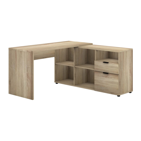
FLOOR AREA
2.5M X2.5M
75 MIN
REQUIRED ASSEMBLY SPACE
APPROXIMATE ASSEMBLY TIME
2 PERSON ASSEMBLY
REQUIRED ASSEMBLY TOOLS
e�
TIT
D=
EB �
'---
-/
EB 8
POZI SCREWDRIVER
HAMMER
MEASURING TAPE
DRILL
ASSEMBLED DIMENSIONS
0
LO
r,...
1/27
CA2129M 171 SJ00-01
Advertisement

Subscribe to Our Youtube Channel
Related Manuals for fantastic furniture MILANO DESK


Summary of Contents for fantastic furniture MILANO DESK
- Page 1 • • • FLOOR AREA 2.5M X2.5M 75 MIN REQUIRED ASSEMBLY SPACE APPROXIMATE ASSEMBLY TIME 2 PERSON ASSEMBLY REQUIRED ASSEMBLY TOOLS e� EB � '--- EB 8 POZI SCREWDRIVER HAMMER MEASURING TAPE DRILL ASSEMBLED DIMENSIONS r,... 1/27 CA2129M 171 SJ00-01...
- Page 2 Tips before you start: Please check that all parts are present before you start the assembly of your furniture. For ease and speed of assembly, we recommend that before you commence each step of the assembly, that you identify all the parts required for that step. For larger items, please ensure that you have sufficient space and people ( as indicated on page 1 ) to assemble your product safely.
- Page 3 Tips before you start: QUICKFIT Tighten quickfit until shoulder is flush with panel. Do not overtighten or undertighten. CAM LOCK WRONG CORRECT When fitting cam lock, ensure starting position is correct before you insert connecting quickfit. • Quickfit head should be in the centre of the cam lock when the two panels are joined.
-
Page 4: Part List
PART LIST: PART NAME PART NAME SIDE PANEL (LEFT) DIVIDER PANEL (LEFT) TOP PANEL (LEFT) SHELF PANEL REAR SUPPORT PANEL (LEFT) FRONT RAIL PANEL DRAWER FRONT (TOP) FRONT SUPPORT PANEL (LEFT) DRAWER FRONT (BOTTOM) REAR SUPPORT PANEL (RIGHT) DRAWER SIDE (TOP LEFT) FRONT SUPPORT PANEL (RITHT) DRAWER SIDE (TOP RIGHT) SIDE SUPPORT PANEL (LEFT) - Page 5 PART LIST: 5/27...
-
Page 6: Hardware List
HARDWARE LIST ©x6 @X lS @ Xl 2 �mmmm � � SCREW CSK SCREW CSK SCREW CSK SCREW M4.7 X38MM M4.5X32MM M4X32MM M3.5X 15MM (E)X2 (Q)X8 (8)X4 ► @ll) � CSK SCREW CSK SCREW EURO SCREW WOOD DOWEL M3.5X 12MM M5.5X 16MM M6X9MM 06X20MM... - Page 7 STEP 1 Using glue (U) insert dowel (H ) into pieces (20, 21, 22 & 23), and dowel (J) into pieces (3, 4, 5, 6, 7, 8, 9, 14, 15 & 17) as shown. 7/27...
- Page 8 STEP2 Attach CAM PINS (K) to the panels (2, 3, 4, 5, 6, 12, 18 & 19) and using a drill on low speed/ torque or a phillips head screw driver. 8/27...
- Page 9 STEP3 Attach drawer sides (20 & 21) to drawer backs (24) using screw 32mm (B). STEP4 Slot drawer bottoms (25) into drawer frame. 9/27...
- Page 10 STEPS Attach drawer front (18) to drawer frame using glue (U) and CAM LOCK (M). STEP 6 Attach panel (22 & 23) to drawer front (19) using glue (U) and CAM LOCKS (M). 10/27...
- Page 11 STEP7 Slot drawer bottoms (27) into drawer frame. STEP 8 Insert wire rod (R) to the hole as shown. Attach drawer back (26) to side of the drawer using 32mm screws (B). 11/27...
- Page 12 STEP 9 Attach drawer slide insert (Pl & P2) to the drawer sides (20 & 21 / 22 & 23) with the 12mm screws (E) ensuring using the correct holes as shown in diagram. ::::;:: r� � -1 ,, J :::::: :::::: ::::o:::...
- Page 13 STEP11 Attach panels (9) to panels (5 & 6) using glue (U) and CAM LOCKS (L) as shown. 13/27...
- Page 14 STEP12 Attach frame to panels (10 & 11) using 32mm screw (B) as shown. STEP13 Attach panels (17) into panels (11 & 14) using glue (U) as shown. 14/27...
- Page 15 STEP14 Attach top panels (12) to frame using glue (U) and CAM LOCKS (L) as shown. 15/27...
- Page 16 STEP15 Slot rear panel (28) into frame. 16/27...
- Page 17 STEP16 Attach panels (16) using 32mm screw (A) as shown. 17/27...
- Page 18 STEP17 Attach plastic sofa leg (W) with screw 32mm (C) to bottom of chest as shown. 18/27...
- Page 19 STEP18 Slot the shelf panel (16) into the body after fix in the metal adjustable shelf stud (S) on the holes as shown. 19/27...
- Page 20 STEP19 Attach panels (7 & 8) to panels (3 & 4) using glue (U) and CAM LOCKS (L) as shown. 20/27...
- Page 21 STEP 20 Attach top panels (2) to frame using glue (U) and CAM LOCKS (L) as shown. 21/27...
- Page 22 STEP 21 Attach panels (1) to top frame using 32mm screw (B). 22/27...
- Page 23 STEP 22 Attach panel connecting bracket (X) to panel (1 & 2) using 16mm screw (F). Then attach plastic leg stud (Q) to bottom panel as shown. � F � ] F � .,_ X l � · : ----- 23/27...
- Page 24 STEP 23 Insert metal pin (V) into hole at panel 12 for joint table and dresser body. 24/27...
- Page 25 STEP 24 Insert the completed drawer boxes into the dresser body. 25/27...
- Page 26 STEP 25 Attach the backply stoppers (T) to the rear panel (28) using 15mm screws (D). r@ml� �� 26/27...
- Page 27 ASSEMBLY IS COMPLETE 27/27...
Need help?
Do you have a question about the MILANO DESK and is the answer not in the manual?
Questions and answers