Soundoff Signal mpower EMPSC07M Series Quick Start Manual
- 7x3 quick mount, screw mount, & stud mount
Hide thumbs
Also See for mpower EMPSC07M Series:
- Manual (10 pages) ,
- Installation instructions manual (9 pages) ,
- Quick start manual (8 pages)
Table of Contents
Advertisement
Quick Links
EMPSC07M(x)-(x) - 7X3 Quick Mount, Screw Mount, & Stud Mount
EMPSB0C9(x)-(x) - 6X4 Quick Mount, Screw Mount, & Stud Mount
Protected by U.S. Patent 10,703,260 and Patents Pending
https://soundoffsignal.com/legal/patent-notification/
WARNING
• HIGH CURRENT interconnects must be properly terminated. Poor crimp
quality can cause heat build-up and fire. Follow the crimp connector
manufacturer instructions.
• DO NOT install this product or route any wires in the Air Bag Deployment
Zone. Refer to vehicle Owner's Manual for deployment zones.
• Do NOT use system to disconnect headlights, brake lights or other safety
equipment.
• Unit may become hot to touch during normal operation.
• Failure to properly install connectors, fuses or wiring may cause vehicle
failure or fire.
• Installation must only be performed by trained technician. Installer must
determine vehicle wiring configuration and proper integration of system.
• Use proper wire gauge. All power wires connecting to positive (+) or
negative (-) battery terminal or local chassis ground (-) must be sized to
supply at least 125% of max. current and properly fused at power source.
• Install protective grommets when routing wire through firewall or metal.
• Petroleum/silicone based lubricants will cause the silicone lens to discolor.
1.800.338.7337 / www.soundoffsignal.com
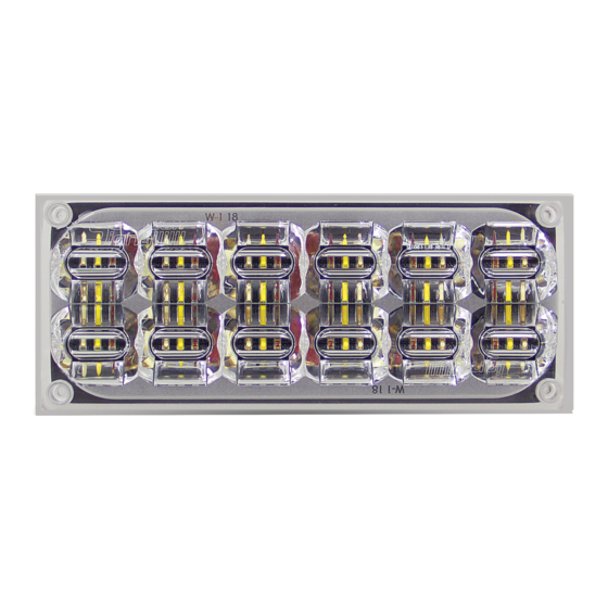
STOP/TAIL & TURN LIGHTS
7x3 Stop/Tail Shown
NOTICE:
Installers and users must comply with all applicable federal, state and local laws regarding use and installation of warning
devices. Improper use or installation may void warranty coverage.To review our Limited Warranty Statement & Return Policy
for this or any SoundOff Signal product, visit our website at www.soundoffsignal.com/tech-services/returns/. If you have
questions regarding this product, contact Technical Services, Monday - Friday, 8 a.m. to 5 p.m. ET at 1.800.338.7337 (press
#4). Questions or comments that do not require immediate attention may be emailed to techservices@soundoffsignal.com.
E N H A N C I N G S A F E T Y T H R O U G H I N N O VAT I O N
With Clear Duty® Technology
DIMENSIONS . . . . . . . . . . . . . . . . . . 2
STT LIGHT OPTIONS . . . . . . . . . . . . . . 2
TECHNICAL SPECIFICATIONS . . . . . . 3
WIRING INFORMATION . . . . . . 4-5
QUICK MOUNT INSTALLATION . . . . . 6
STUD MOUNT INSTALLATION . . . . . 6
SCREW MOUNT INSTALLATION . . . . 7
RETENTION CLIP INSTRUCTIONS . . . 8
6x4 Stop/Tail Shown
!
ROUTE WIRES ONLY IN LOCATIONS THAT ARE NOT SUBJECTED TO
POTENTIAL WEAR. MAKE SURE TO AVOID ROUTING WIRES IN THE
DEPLOYMENT AREA OF YOUR AIR BAG. REFER TO YOUR VEHICLE'S
OWNER'S MANUAL FOR AIRBAG DEPLOYMENT ZONES.
00KPJL 0822 REV B
Advertisement
Table of Contents

Related Manuals for Soundoff Signal mpower EMPSC07M Series


Summary of Contents for Soundoff Signal mpower EMPSC07M Series
-
Page 1: Table Of Contents
Improper use or installation may void warranty coverage.To review our Limited Warranty Statement & Return Policy for this or any SoundOff Signal product, visit our website at www.soundoffsignal.com/tech-services/returns/. If you have questions regarding this product, contact Technical Services, Monday - Friday, 8 a.m. to 5 p.m. ET at 1.800.338.7337 (press #4). -
Page 2: Dimensions
• 7x3 - EMPSC0 XXX-X** • 6x4 - EMPSB0 XXX-X** 7x3 & 6x4 CERTIFICATIONS • FMVSS180 **See SoundOff Signal configurator or sales representative for specific color, lens, and mounting options. 1.800.338.7337 / www.soundoffsignal.com 7X3 / 6X4 Silicone_STT 00KPJL 0822 REV B... -
Page 3: Technical Specifications
TECHNICAL SPECIFICATIONS: MPOWER 7X3 & 6X4 STOP/TAIL LIGHT ® TECHNICAL SPECIFICATIONS Input Voltage: 9-32Vdc STOP/TAIL LIGHT CURRENT CONSUMPTION (Amps) 12.8Vdc 25.6Vdc Peak Peak STOP 0.42 0.21 TAIL 0.04 0.02 AFTER POWER IS ON, touching the WHITE wire to the ground will allow you to change various settings on the module. -
Page 4: Wiring Information
WIRING AND TABLE INFORMATION: OVER-VOLTAGE PROTECTION WIRE HOOK-UP TABLE When an over-voltage condition is detected, the module will flash an overvoltage warning pattern of 50mS ON/950mS OFF to alert of the overvoltage condition and WIRE COLOR: FUNCTION: protect the electronics from damage due to heat/voltage. Power (Stop/Turn Function) THERMAL COMPENSATION PROTECTION BLACK... - Page 5 TYPICAL TRAILER CIRCUIT SCHEMATIC AFTERMARKET RELAY ISOLATION SCHEMATIC 1.800.338.7337 / www.soundoffsignal.com 7X3 / 6X4 Silicone_STT 00KPJL 0822 REV B...
-
Page 6: Quick Mount Installation
QUICK MOUNT INSTALLATION: FIG. 6 1. Drill a 3/4" wire hole (see Fig. 7). WIRE HOLE 2. Insert (4) Silicone Plugs into Light to Seal Screw Holes. (Use a 50% VHB QUICK MOUNT Isopropyl alcohol, 50% deionized water mix for lubrication if necessary). -
Page 7: Screw Mount Installation
SCREW MOUNT INSTALLATION: Drill (4) 5/16" holes to mount light. Drill 3/4" wire hole. See FIG. 10 Fig. 11(7x3) or Fig. 12(6x4). PLACE LIGHT INTO BEZEL, P WIRE HOLE AND GASKET AGAINST MO If a bezel is being used, place the light into the bezel. WIRE HARNESS Place the gasket on the back of the light and bezel (if GASKET... -
Page 8: Retention Clip Instructions
RETENTION CLIP INSTRUCTIONS: NOTE: In the event the harness needs to be disengaged from the light, these instructions can be used to reattach and apply the retention clip. 1. Plug harness into light housing, aligning tab to window, as shown in Fig 13. 2.
Need help?
Do you have a question about the mpower EMPSC07M Series and is the answer not in the manual?
Questions and answers