Table of Contents
Advertisement
Quick Links
Advertisement
Table of Contents

Related Manuals for Multitech MultiConnect microCell


Summary of Contents for Multitech MultiConnect microCell
- Page 1 ® MultiConnect microCell MTCM-LNA3 User Guide...
- Page 2 Legal Notices The MultiTech products are not designed, manufactured or intended for use, and should not be used, or sold or re-sold for use, in connection with applications requiring fail-safe performance or in applications where the failure of the products would reasonably be expected to result in personal injury or death, significant property damage, or serious physical or environmental damage.
-
Page 3: Table Of Contents
CONTENTS Contents Chapter 1 – Product Overview ..........................5 About the MultiConnect microCell Modem ......................... 5 Documentation Overview ............................. 5 Dimensions..................................6 MTCM-LNA3 Specifications............................7 LED Descriptions ................................8 Power Measurements..............................8 MTCM-LNA3 Power Draw ............................9 Chapter 2 – Safety Warnings..........................10 Radio Frequency (RF) Safety ............................ - Page 4 CONTENTS Configuring Device as UDP Client to Connect to UDP Server ................... 20 Transferring FTP File to FTP Server ........................... 21 Downloading File from FTP Server..........................23 Reading, Writing and Deleting Messages ........................24 Sending Text Messages ............................. 24 Reading Text Messages............................. 25 Deleting Messages ..............................
-
Page 5: Chapter 1 - Product Overview
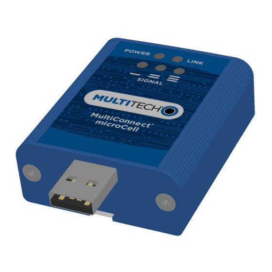
Chapter 1 – Product Overview About the MultiConnect microCell Modem The MultiConnect microCell is a compact and simple communications platform that provides cellular capabilities for fixed and mobile applications. It is intended for use in settings such as vending, smart parking, medical, smart inventory tracking equipment and commercial applications. -
Page 6: Dimensions
PRODUCT OVERVIEW Dimensions ® MultiConnect microCell MTCM-LNA3 User Guide... -
Page 7: Mtcm-Lna3 Specifications
PRODUCT OVERVIEW MTCM-LNA3 Specifications Category Description General Standards LTE 3GPP Release 9 HSPA+ 21/GPRS fallback USB Interface is CDC-ACM compliant TCP/IP Functions FTP, SMTP, SSL, TCP, UDP Frequency Bands 4G: 1900 (B2) / AWS 1700 (B4) / 850 (B5) / 700 (B12/13) 3G: 1900 (B2) / 850 (B6) Speed Data Speed... -
Page 8: Led Descriptions
PRODUCT OVERVIEW Category Description Certifications and Compliance EMC Compliance FCC Part 15 Class B Radio Compliance FCC Part 22H, 24E, 27 Safety Compliance UL 60950-1 2nd ED cUL 60950-1 2nd ED IEC 60950-1 2nd ED Network Compliance PTCRB Carrier AT&T and Verizon LED Descriptions The top panel contains the following LEDs: Power LED—The Power LED indicates that DC power is present. -
Page 9: Mtcm-Lna3 Power Draw
PRODUCT OVERVIEW MTCM-LNA3 Power Draw Radio Sleep Mode Live Cellular Measured TX Pulse Total Inrush Total Protocol Connection, Connection Current at Amplitude Charge Inrush Idle Current Idle, No Max Power Current for Duration Data Peak During Current Power Up 5 Volts WCDMA 56 mA 56 mA... -
Page 10: Chapter 2 - Safety Warnings
SAFETY WARNINGS Chapter 2 – Safety Warnings Radio Frequency (RF) Safety Due to the possibility of radio frequency (RF) interference, it is important that you follow any special regulations regarding the use of radio equipment. Follow the safety advice given below. Operating your device close to other electronic equipment may cause interference if the equipment is inadequately protected. -
Page 11: Chapter 3 - Installing And Using The Device
INSTALLING AND USING THE DEVICE Chapter 3 – Installing and Using the Device Installing the Device Important: Install drivers on your computer before connecting the device. Connect antennas to the antenna connectors. Connect the USB connector to your computer or other USB high power device, such as a hub. The POWER LED lights after the device powers up. - Page 12 INSTALLING AND USING THE DEVICE Slide the mounting bracket through the groove. To secure the bracket to the desired surface, place and tighten two screws in the holes on either end of the mounting bracket. The dimensions illustration in this guide shows the mounting bracket, as well as the dimensions for placement of the screws.
-
Page 13: Chapter 4 - Antenna Information
ANTENNA INFORMATION Chapter 4 – Antenna Information Notice regarding Compliance with FCC, EU, and Industry Canada Requirements for RF Exposure The antenna intended for use with this unit meets the requirements for mobile operating configurations and for fixed mounted operations, as defined in 2.1091 of the FCC rules for satisfying RF exposure compliance. This device also meets the European RF exposure requirements of EN 62311. - Page 14 ANTENNA INFORMATION Category Description Radiation Omni-directional Polarization Linear Connector SMA(M) ® MultiConnect microCell MTCM-LNA3 User Guide...
-
Page 15: Chapter 5 - Configuring And Communicating With Your Device
CONFIGURING AND COMMUNICATING WITH YOUR DEVICE Chapter 5 – Configuring and Communicating with Your Device Before Using the Device Before using the device: Install any drivers. Refer to the separate driver installation guide for your device. Power up your device and ensure it is connected to your computer that issues AT commands. Note: Wait 10 seconds after power-up before issuing any AT commands. -
Page 16: Dual Carrier Firmware For Cellular Radio
CONFIGURING AND COMMUNICATING WITH YOUR DEVICE Dual Carrier Firmware for Cellular Radio This device uses a cellular radio with dual carrier firmware meaning that it can be used on different carrier networks (not simultaneously). The device can be used on either the Verizon or AT&T/other networks. To check that your device is configured for the desired network: AT#FWSWITCH? If response is:... -
Page 17: Verizon Fota (Firmware Over The Air)
Verizon’s LTE requirements, you must implement FOTA. Failure to perform a critical update could result in losing access to the Verizon network. MultiTech has developed a script for customers to use in order to initiate a FOTA update from the (the customer’s) local host processor (pull FOTA). The script is available at: https://www.multitech.com/vzw-catm1... -
Page 18: Example
CONFIGURING AND COMMUNICATING WITH YOUR DEVICE Example A example response to AT+CSQ: +CSQ: 15,1 Checking Network Registration Before establishing a packet data connection, verify the is device registered on the network. To do this enter the network registration report read command: AT+CEREG? If the device returns: +CEREG: 0,1... -
Page 19: Configuring Device As Udp Listener To Accept Udp Client Connections
CONFIGURING AND COMMUNICATING WITH YOUR DEVICE AT#SGACT=3,1 Other Networks: AT#SGACT=1,1 The device responds with the IP Address the cellular provider assigned to the device on connection, followed by OK. For example: #SGACT: 25.194.185.116 Create Client Connection to TCP Server on Port 500 Enter: AT#SD=1,0,500,"###.##.###.##"... -
Page 20: Configuring Device As Udp Client To Connect To Udp Server
CONFIGURING AND COMMUNICATING WITH YOUR DEVICE Configure socket parameters Enter: AT#SCFG=1,3,300,240,600,50 Activate context one Enter: Verizon: AT#SGACT=3,1 Other Networks: AT#SGACT=1,1 Set firewall rule to accept connections: AT#FRWL=1,"###.##.###.#","###.##.###.#" where ###.##.###.# represents the IP range. For example: AT#FRWL=1,"204.26.122.1","204.26.122.255" Set connection ID 1 for UDP listening mode on port 7000. Enter: AT#SLUDP=1,1,7000 The device responds with and unsolicited indication that a host is trying to connect to connection ID 1 on... -
Page 21: Transferring Ftp File To Ftp Server
CONFIGURING AND COMMUNICATING WITH YOUR DEVICE Enter: AT+CSQ Verify device is registered on the cellular network. Enter: AT+CEREG? Should return: +CEREG: 0,1 or +CEREG: 0,5 Configure socket parameters Enter: AT#SCFG=1,3,300,240,600,50 Activate context one Enter: Verizon: AT#SGACT=3,1 Other Networks: AT#SGACT=1,1 Create UDP connection to Server port Enter: AT#SD=1,1,####,"###.##.###.##"... - Page 22 CONFIGURING AND COMMUNICATING WITH YOUR DEVICE Verify device is registered on the cellular network. Enter: AT+CEREG? Should return: +CEREG: 0,1 or +CEREG: 0,5 Activate context Enter: Verizon: AT#SGACT=3,1 Other Networks: AT#SGACT=1,1 Set FTP operations timeout to 10 seconds Enter: AT#FTPTO=100 Configure FTP server IP address with username and password.
-
Page 23: Downloading File From Ftp Server
CONFIGURING AND COMMUNICATING WITH YOUR DEVICE Verizon: AT#SGACT=3,0 Other Networks: AT#SGACT=1,0 The device responds with OK. Downloading File from FTP Server To connect to an FTP server and download files: Check signal strength. Enter: AT+CSQ Verify device is registered on the cellular network. Enter: AT+CEREG? Should return:... -
Page 24: Reading, Writing And Deleting Messages
CONFIGURING AND COMMUNICATING WITH YOUR DEVICE CONNECT The file is received through the device. The device responds with: NO CARRIER The data connection closes automatically when the file sending ends. Closing the FTP Data Connection After the file is sent: Close the FTP connection. -
Page 25: Reading Text Messages
CONFIGURING AND COMMUNICATING WITH YOUR DEVICE Enter CTRL+Z. The device responds: +CMGS: # where # is the reference number of the sent message. For example: AT+CMGF=1 AT+CMGS="0001112222" > How are you? <CTRL+Z to send> +CMGS: 255 Where 0001112222 is the phone number. Reading Text Messages NOTE: For CAT M1 devices, you can only send/receive SMS messages from other CAT M1 devices on the same network. - Page 26 CONFIGURING AND COMMUNICATING WITH YOUR DEVICE Deletes all read and sent device-originated messages. Leaves unread messages and unsent device-originated messages. Deletes all read messages and sent and unsent device-orginated messages. Leaves unread messages. Deletes all messages. For example: AT+CMGD=1 (delete message at index 1) AT+CMGD=2 (delete message at index 2 ) AT+CMGD=1,0 AT+CMGD=1,1...
-
Page 27: Chapter 6 - Regulatory Information
REGULATORY INFORMATION Chapter 6 – Regulatory Information Industry Canada Class B Notice This Class B digital apparatus meets all requirements of the Canadian Interference-Causing Equipment Regulations. Cet appareil numérique de la classe B respecte toutes les exigences du Reglement Canadien sur le matériel brouilleur. -
Page 28: Restriction Of The Use Of Hazardous Substances (Rohs)
2015/863 of the European Parliament (Restriction of the use of certain Hazardous Substances in electrical and electronic equipment - RoHS 3). These MultiTech products do not contain the following banned chemicals Lead, [Pb] < 1000 PPM Mercury, [Hg] <... -
Page 29: Information On Hs/Ts Substances According To Chinese Standards
REGULATORY INFORMATION Information on HS/TS Substances According to Chinese Standards In accordance with China's Administrative Measures on the Control of Pollution Caused by Electronic Information Products (EIP) # 39, also known as China RoHS, the following information is provided regarding the names and concentration levels of Toxic Substances (TS) or Hazardous Substances (HS) which may be contained in Multi-Tech Systems Inc. -
Page 30: Information On Hs/Ts Substances According To Chinese Standards (In Chinese)
REGULATORY INFORMATION Information on HS/TS Substances According to Chinese Standards (in Chinese) 依 依 照 照 中 中 国 国 标 标 准 准 的 的 有 有 毒 毒 有 有 害 害 物 物 质 质 信 信 息 息 根据中华人民共和国信息产业部... -
Page 31: Chapter 7 - Using Connection Manager
Click Connection Manager. Open or unzip the Connection Manager file and run the installer (.msi file). In the MultiTech Connection Manager Setup Wizard, read the end-user license agreement and check I accept the terms in the License Agreement. Click Next to have the installer automatically disable the native WWAN AutoConfig service in Windows. -
Page 32: Setting Up A Serial Device In Windows Device Manager
To specify a folder for Connection Manager, use the default folder or click Change to browse to the folder you want to use. Click Install. A separate wizard opens for installing Telit drivers. Some MultiTech devices use embedded modules from Telit Wireless Solutions to provide cellular connectivity; these devices require Telit drivers. Select Complete setup type. - Page 33 USING CONNECTION MANAGER In the Add Hardware Wizard: Click Next. Select Install the hardware that I manually select from a list, then click Next. Select Modems, then click Next. Check Don't detect my modem; I will select it from a list, then click Next. Select Standard Modem Types, then select Standard 33600 bps Modem on the right.
-
Page 34: Connecting A Device
USING CONNECTION MANAGER Connecting a Device Before You Begin Make sure that your device is connected to the computer where Connection Manager is installed. Set up the device in Device Manager. Refer to Setting Up a Serial Device in Windows Device Manager. -
Page 35: Uninstalling Connection Manager
The steps above describe how to uninstall Connection Manager using Control Panel. You can also uninstall the application by using the installer file (.msi). Double-click the file, in the MultiTech Connection Manager Setup Wizard, click Next, and then select Remove on the next two pages. -
Page 36: Connection Manager User Interface
USING CONNECTION MANAGER Connection Manager User Interface Connection Manager consists of the following tabs: Main Settings Connection Details Terminal Charts Main tab The Main tab displays the following: Status of device connection: Searching, Connecting, Connected, Disconnecting, or Disconnected The action button, which changes according to the current device connection status: Detect, Connect, or Disconnect Signal strength bars and percentage indicator (only when connection to the carrier's network is established) Note:... -
Page 37: Settings Tab
USING CONNECTION MANAGER Connection statistics: download and upload speeds, amount of traffic sent and received (only when connection to the carrier's network is established) The keep-alive check status and when the last ping response was received if Enable keep-alive check is checked on the Connection tab. -
Page 38: Troubleshooting
USING CONNECTION MANAGER Troubleshooting Serial COM port is not available in the Serial Modem Settings Close Connection Manager and reopen it. Device is not detected ("No Device") After following the steps to activate your device, the Main tab still indicates "No Device." Try the following steps: Click the Settings tab and make sure that the appropriate modem type is selected: USB or Serial.
Need help?
Do you have a question about the MultiConnect microCell and is the answer not in the manual?
Questions and answers