Multitech MTCBA-E1-U User Manual
Hide thumbs
Also See for MTCBA-E1-U:
- User manual (29 pages) ,
- User manual (37 pages) ,
- User manual (37 pages)
Table of Contents
Advertisement
Quick Links
Advertisement
Table of Contents

Related Manuals for Multitech MTCBA-E1-U


Summary of Contents for Multitech MTCBA-E1-U
- Page 1 ® MultiModem Cell Wireless Modem User Guide...
- Page 2 Copyright and Technical Support MultiModem® Cell User Guide Wireless Modem MTCBA-E1, MTCBA-E1-U, MTCBA-C1, MTCBA-C1-U, MTCBA-G2, MTCBA-G2-U, MTCBA-H5, MTCBA-H5-U S000489, Revision H Copyright This publication may not be reproduced, in whole or in part, without prior expressed written permission from Multi-Tech Systems, Inc. All rights reserved.
-
Page 3: Table Of Contents
Front Panel..................................8 LEDs ....................................9 Package Contents ................................10 Specifications ................................10 MTCBA-E1 and MTCBA-E1-U ............................10 MTCBA-C1 and MTCBA-C1-U ............................11 MTCBA-G2 and MTCBA-G2-U ............................13 MTCBA-H5 and MTCBA-H5-U ............................14 9-Pin Fem-D Sub Serial Connector ..........................17 4-Position DIP Switch .............................. - Page 4 Contents EMC, Safety, and R&TTE Directive Compliance ......................31 International Modem Restrictions ..........................31 EMC Requirements for Industry Canada ........................32 Waste Electrical and Electronic Equipment Statement ....................32 WEEE Directive ................................32 Instructions for Disposal of WEEE by Users in the European Union ................32 REACH Statement ................................
-
Page 5: Chapter 1 - Product Description And Specifications
Model Description MTCBA-E1 Quad-band E-GPRS Class 12 performance and either RS232 serial interface or RS422 serial interface MTCBA-E1-U Quad-band E-GPRS Class 12 performance and USB connectivity MTCBA-C1 Multi-band CDMA2000 1xRTT performance and either RS232 serial interface or RS422 serial interface... -
Page 6: Related Documentation
Chapter 1 – Product Description and Specifications Related Documentation The following table describes additional documentation for each model. Model Additional Documentation MultiModem MTCBA-E1 (EDGE) You can configure the MultiModem MTCBA-E1 wireless router using the EDGE AT Commands. For more information refer to the Reference Guide for the MultiModem Wireless EDGE Modems, part number S000474x. -
Page 7: Interference With Pacemakers And Other Medical Devices
Chapter 1 – Product Description and Specifications Switch OFF your wireless device in hospitals and any other place where medical equipment may be in ● use. Sécurité RF En raison de la possibilité d'interférences de radiofréquence (RF), il est important que vous suiviez une quelconque réglementation concernant l'utilisation du matériel radio. -
Page 8: Vehicle Safety
Chapter 1 – Product Description and Specifications Keep the device on the opposite the side of the body from the pacemaker to add extra distance between the ● pacemaker and the device. Avoid placing a turned-on device next to the pacemaker (for example, don’t carry the device in a shirt or ●... -
Page 9: Leds
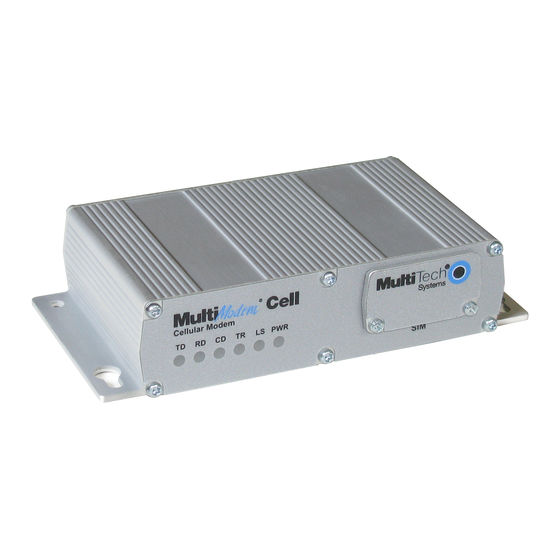
Chapter 1 – Product Description and Specifications LEDs LED Indicators Transmit Data: Lit when modem is transmitting data. Receive Data: Lit when modem is receiving data. Carrier Detect: Lit when data connection has been established. Terminal Ready: Lit when modem is transmitting data. Link Status Dependent on Model -E1 version* (AT^SSYNC=1) -G2 version... -
Page 10: Package Contents
Note: You must supply mounting screws, AC or DC 1 RS232 or USB cable power supply, and an antenna. 1 power supply with serial versions Note: You must supply mounting screws. Specifications MTCBA-E1 and MTCBA-E1-U Category Description General Performance Edge: E-GPRS Class 12... -
Page 11: Mtcba-C1 And Mtcba-C1-U
été évaluée par UL. La certification UL ne s'applique pas ou s'étendre à utiliser dans des véhicules ou les applications en extérieur ou dans ambiante dépasse 40 ° C.» Power MTCBA-E1-U Sleep Typical Maximum... - Page 12 Chapter 1 – Product Description and Specifications Category Description RS232 Connector USB Connector Type B Power Requirements Voltage 9 V to 32 V DC (serial only) 5.0 V (USB input voltage supplied by USB connector) Physical Description Dimensions (L x W x H) 2.35 in x 4.11 in x 1.07 in 8.6 cm x 12.5 cm x 2.7 cm Weight (Device only)
-
Page 13: Mtcba-G2 And Mtcba-G2-U
Chapter 1 – Product Description and Specifications Actual performance speeds may be affected by a variety of attributes such as cell tower distance, data loads, position of the sun, wind speeds, packet sizes, etc. UL Listed @ 40°C, limited by power supply. UL Certification does not apply or extend to an ambient above 40°C and has not been evaluated by UL for ambient greater that 40°C. -
Page 14: Mtcba-H5 And Mtcba-H5-U
Chapter 1 – Product Description and Specifications Category Description (verified tested temp) -40° to 85° C Storage Temperature -40°to 185° F -40° to 85° C Humidity Relative humidity 20%-90% noncondensing Certifications, Compliance EMC Compliance FCC Part 15 EN55022 EN55024 Radio Compliance FCC Part 22, 24 RSS132, 133 EN301 489-1... - Page 15 Chapter 1 – Product Description and Specifications Category Description Text & PDU, Point-to-Point, Cell broadcast Connectors Power Connector 2.5mm miniature (screw-on) RF Antenna Connector 50 ohm SMA (female connector) RS232 Connector SIM Connector Standard 1.8 and 3 V SIM receptacle USB Connector Type B Power Requirements...
- Page 16 Chapter 1 – Product Description and Specifications (Inrush Current) 9 volts 0.032A, 0.062A, 0.155A, 1.43W 1.24A 1.60A 0.296W 0.57W 20 volts 0.020A, 0.034A, 0.076A, 1.52W 0.555A 1.645A 0.400W 0.68W 32 volts 0.014A, 0.025A, 0.051A, 1.63W 0.363A 1.48A 0.448W 1.25W HSDPA Sleep Typical Maximum...
-
Page 17: 9-Pin Fem-D Sub Serial Connector
Chapter 1 – Product Description and Specifications 9-Pin Fem-D Sub Serial Connector The following table explains the pin functions. DE9 Pin Assignment Female Connector RS232 Signals RS422 Full Signal Pins Duplex Signals Direction Data Carrier Detected Pin 1 RxD- (DCD) Pin 2 RxD+ Pin 3... -
Page 18: Chapter 2 - Activating And Installing
Chapter 2 – Activating and Installing Activating Your Wireless Account Refer to the wireless account Activation Notices included with your unit. Choose the notice for your wireless network provider and follow the directions to activate your account. Phone Numbers for the Wireless Modem Every wireless modem has a unique phone number. -
Page 19: Connecting The Antenna, Serial Or Usb Cable, Power, Optional Power Or Voice Cable
Chapter 2 – Activating and Installing Connecting the Antenna, Serial or USB Cable, Power, Optional Power or Voice Cable MTCBA-H5 models do not support voice. The Voice jack is not included on MTCBA-H5 models. Connect a suitable antenna to the ANT connector on the right side of the unit. See antenna specifications in Chapter 1. -
Page 20: Optional Mounting
Chapter 2 – Activating and Installing For Optional Direct DC Power Screw-on the DC power cable to the power connector on the modem. ● Then attach the two wires at the other end of the DC power cable to a DC fuse/terminal block. ●... -
Page 21: Installing Usb Cdc-Acm Virtual Com Port
Chapter 2 – Activating and Installing Installing USB CDC-ACM Virtual COM Port Note: To install the USB driver for the MTCBA-H5-U model, download the guide USB Driver Installation Guide, part number S000553. Follow the instructions in that guide to install the USB driver. Windows XP (SP3 or greater), VISTA, 2003 Server, Windows 7 (32-bit or 64-bit), Linux (Kernel 2.6.xx using CDC-ACM module) are supported. - Page 22 Chapter 2 – Activating and Installing When the Phone and Modem Options window appears, click Add. On the Install New Modem window, click Don’t detect my modem, I will select it from a list. Then click Next. On the Install New Modem screen, click the Have Disk button to browse for the driver file that you downloaded from the Multi-Tech website.
- Page 23 Chapter 2 – Activating and Installing Click Next. Browse to the location where you downloaded the driver. Select the MTSMCIP_MTCMRIP.INF file. Then click OK. In the Models window, scroll down the list of Models and select the model that is applicable to your modem. MultiModem Cell User Guide...
- Page 24 Chapter 2 – Activating and Installing Once you have selected your model, click Next. Choose the com port to which the MultiModem is connected. If you know exactly which port your modem is on, click on that port; otherwise, go to Device Manager > Ports (COM &...
- Page 25 Chapter 2 – Activating and Installing You have now successfully installed the MultiModem driver to your PC. Verifying That Your Modem is Installed Successfully After you have successfully installed the MultiModem driver as stated above, you should be brought back to the Phone and Modems Options screen.
-
Page 26: Chapter 3 - Using Your Wireless Modem
Chapter 3 – Using Your Wireless Modem Phone Numbers for the Wireless Modem Every wireless modem has a unique phone number. ● The phone number may simply be given to you by your wireless service provider or it may be on the SIM card ●... -
Page 27: Checking The Modem's Identity
Chapter 3 – Using Your Wireless Modem Checking the Modem’s Identity Use the ATI command. This command uses the capital letter I after AT) Type ATI0 (Note: The command ends in a zero) The manufacturing data displays. For example: Wavecom Modem Multiband G850 1900 Type ATI3 The software version displays. - Page 28 Chapter 3 – Using Your Wireless Modem Set the Access Point Name (APN) into the Modem’s Properties on your PC Before your EDGE modem can connect to your provider’s network, you must tell the modem the APN that it’s going to connect to. The APN is a server name that your account is setup on with your provider. You provider supplies you with your APN.
-
Page 29: Create Your Dial-Up Connection In Windows Vista And Xp
Chapter 3 – Using Your Wireless Modem Create Your Dial-Up Connection in Windows Vista and XP From Start, select Control Panel. In the Control Panel, double-click Network Connections. On the Network Connections screen on the left-hand side under Network Tasks, click Create a new connection. -
Page 30: Generic Dial-Up Method - Non-Windows
Chapter 3 – Using Your Wireless Modem Disconnecting To disconnect the connection: Right click on the connection icon in your system tray. From the menu that appears, select Disconnect. Generic Dial-Up Method - Non-Windows If CDMA, dial onto the network using AT#777 If GPRS/EDGE: a. -
Page 31: Appendix A - Regulatory Compliance
Appendix A – Regulatory Compliance FCC Part 15 Class B Statement This equipment has been tested and found to comply with the limits for a Class B digital device, pursuant to part 15 of the FCC Rules. These limits are designed to provide reasonable protection against harmful interference in a residential installation. -
Page 32: Emc Requirements For Industry Canada
Appendix A – Regulatory Compliance EMC Requirements for Industry Canada This Class B digital apparatus meets all requirements of the Canadian Interference-Causing Equipment Regulations. Cet appareil numérique de la classe B respecte toutes les exigences du Reglement Canadien sur le matériel brouilleur. -
Page 33: Reach Statement
Appendix A – Regulatory Compliance REACH Statement Registration of Substances: After careful review of the legislation and specifically the definition of an “article” as defined in EC Regulation 1907/2006, Title II, Chapter 1, Article 7.1(a)(b), it is our current view Multi-Tech Systems, Inc. products would be considered as “articles”. -
Page 34: Information On Hs/Ts Substances According To Chinese Standards
Appendix A – Regulatory Compliance Information on HS/TS Substances According to Chinese Standards In accordance with China’s Administrative Measures on the Control of Pollution Caused by Electronic Information Products (EIP) # 39, also known as China RoHS, the following information is provided regarding the names and concentration levels of Toxic Substances (TS) or Hazardous Substances (HS) which may be contained in Multi-Tech Systems Inc. -
Page 35: Information On Hs/Ts Substances According To Chinese Standards (In Chinese)
Appendix A – Regulatory Compliance Information on HS/TS Substances According to Chinese Standards (in Chinese) 依照中国标准的有毒有害物质信息 根据中华人民共和国信息产业部 (MII) 制定的电子信息产品 (EIP) 标准-中华人民共和国《电子信息产品污染控制管理办法》(第 39 号),也称作中国 RoHS,下表列出了 Multi-Tech Systems, Inc. 产品中可能含有的有毒物质 (TS) 或有害物质 (HS) 的名称及含量水平方面的信息。 有害/有毒物质/元素 成分名称 铅 汞 镉 六价铬 多溴联苯 多溴二苯醚 (CR6+) (PB) (Hg) -
Page 36: Appendix B - Cellular Information
Appendix B - Cellular Information Antenna System for Cellular Devices The cellular/wireless performance is completely dependent on the implementation and antenna design. The integration of the antenna system into the product is a critical part of the design process; therefore, it is essential to consider it early so the performance is not compromised. -
Page 37: Gsm/Egsm Rf Specifications
Appendix B – Cellular Information GSM/EGSM RF Specifications GSM 850 EGSM 900 GSM 1800 GSM 1900 Frequency RX 869 to 894 MHz 925 to 960 MHz 1805 to 1880 MHz 1930 to 1990 MHz Frequency TX 824 to 849 MHz 880 to 915 MHz 1710 to 1785 MHz 1850 to 1910 MHz... -
Page 38: Antennas Available From Multi-Tech Systems, Inc
Appendix B – Cellular Information Antennas Available from Multi-Tech Systems, Inc. Part Number Description Quantity Quad Band ANQB-1HRA Hinged Right Angle 800/900/1800/1900 MHz Cellular Antenna, 7.5" ANQB-10HRA Hinged Right Angle 800/900/1800/1900 MHz Cellular Antenna, 7.5" ANQB-50HRA Hinged Right Angle 800/900/1800/1900 MHz Cellular Antenna, 7.5" Dual Band ANF1-1HRA Hinged Right Angle 900/1800 MHz Cellular Antenna, 4"... -
Page 39: Appendix C - Dc Power Cable
Appendix C – DC Power Cable DC Power Cable Dimensions MultiModem Cell User Guide...
Need help?
Do you have a question about the MTCBA-E1-U and is the answer not in the manual?
Questions and answers