Advertisement
Quick Links
Advertisement

Related Manuals for BDI VOCA 3501


Summary of Contents for BDI VOCA 3501
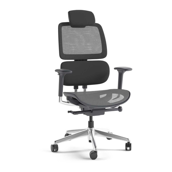
- Page 1 VOCA 3501 ® OFFICE CHAIR INSTRUCTION MANUAL LET’S GET STARTED. DESIGNED IN DENMARK...
- Page 3 Congratulations on the purchase of your Voca Office Chair 3501 from BDI. Your office chair has been designed to provide a lifetime of enjoyment. This manual will provide you with assembly instructions and other helpful information to ensure that you get the most out of your product.
- Page 4 HARDWARE AND COMPONENTS Unpack and identify the parts listed below. The assembly workspace should be a non-marring surface such as carpet. For missing hardware pieces, please contact BDI Customer Service at customerservice@bdiusa.com. Do not use power tools for the assembly of this product.
- Page 5 HARDWARE AND COMPONENTS PART # PART # DESCRIPTION DESCRIPTION Armrest (Left & Right) Lift Column QUANTITY QUANTITY 1 of each PART # PART # DESCRIPTION Base DESCRIPTION Swivel Wheel QUANTITY QUANTITY NEED ASSISTANCE? customerservice@bdiusa.com BDIUSA.COM | 5...
- Page 6 Using the box as a workbench, position the PART/DESCRIPTION (C1) Backrest Assembly as shown. Connect the (C3) Seat Mechanism to the (C1) Backrest Assembly using 3 (H1) Screws with Washers. T2-HEX WRENCH Tighten with (T2) 5mm Hex Wrench. H1-SCREW 6 | BDIUSA.COM VOCA 3501...
- Page 7 STEP 2. ATTACH ARMREST ASSEMBLY On the other end of the box, place (C2) Seat PART/DESCRIPTION upside down. Attach (C4) Left and Right Armrest using 6 (H3) Screws and tighten with (T1) 4mm Hex Wrench. T1-HEX WRENCH H3-SCREW NEED ASSISTANCE? customerservice@bdiusa.com BDIUSA.COM | 7...
- Page 8 ASSEMBLY STEP 3. ATTACH BACKREST / SEAT MECHANISM Position the Backrest/Seat Mechanism Assembly PART/DESCRIPTION on top of the (C2) Seat. Attach with 4 (H2) Screws and tighten with (T2) 5mm Hex Wrench. T2-HEX WRENCH H2-SCREW 8 | BDIUSA.COM VOCA 3501...
- Page 9 STEP 4. INSTALL LIFT COLUMN ASSEMBLY Position the (C5) Lift Column’s narrow end into the hole on the bottom of the (C3) Seat Mechanism. Press into place. STEP 5. INSTALL SWIVEL WHEELS ASSEMBLY Position the (C6) Base upside down on the carpeted floor. Press the (C7) Swivel Wheels firmly into the holes until they lock.
-
Page 10: Step 6. Connect The Base
ASSEMBLY STEP 6. CONNECT THE BASE Connect the (C6) Base to the chair either right side up (with base on the floor as shown) or upside down on top of the box. 10 | BDIUSA.COM VOCA 3501... - Page 11 FUNCTION ADJUSTING ARMRESTS ADJUSTING BACK HEIGHT Lift the button under the arm to The back support assembly is adjustable with an adjust the height. Further, refine internal lift mechanism. While seated or standing, your settings by grasping the top lift the back to adjust to one of eight preset of the arms and sliding in any positions.
-
Page 12: Warranty
WARRANTY BDI warrants to the original purchaser that this product shall be free of defects in assembly, material, or workmanship for five (5) years from the original date of retail purchase. In the event of a proven defect in this product’s assembly, material, or workmanship within five (5) years from the original date of purchase, BDI will replace any such defective part(s).
Need help?
Do you have a question about the VOCA 3501 and is the answer not in the manual?
Questions and answers