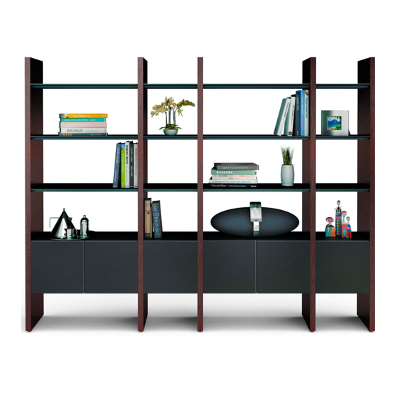
Summary of Contents for BDI SEMBLANCE
- Page 1 M O D U L A R S Y S T E M MAIN ASSEMBLY INSTRUCTIONS To view the Semblance assembly video, scan this code with a QR reader or visit http://www.bdiusa.com/semblance/ assembly.shtml B D I U S A . C O M...
-
Page 2: You Will Need
Semblance System Your SEMBLANCE System Furniture is engineered for easy assembly. Carefully follow this procedure to prevent any damage. Placement and Maintenance SEMBLANCE System Furniture is designed for indoor use on level floors. Clean glass with glass cleaner, steel parts and wood veneer with a moist cloth. -
Page 3: Shelf Assembly
See page 3 for a representation of your For missing hardware pieces, please Package containing critical information for contact BDI Customer Service at its assembly. customerservice@bdiusa.com. For all other concerns, please contact your BDI Retailer. Model Details Component List 15010 Single Spacing... - Page 4 WALL SYSTEM Assembly Sequence Overview Level each Panel as it is being assembled. Use Leveler Wrench (F) to adjust the height of the Panel, if necessary.
-
Page 5: Plan Ahead
Plan Ahead. To plan unit placement, refer to Package Reference Booklet for critical dimensions. The assembled unit CANNOT be moved, so carefully plan the placement of the unit prior to building. See the Bracket Template spacing dimension on page 3 of the Package Reference Booklet. - Page 6 Align the left side of the Bracket Template with the wall mark. Level the Template with the string, and insert Wall Bracket (B) into its designated groove. Mark the wall at bracket holes to locate fastener locations. Attach first Bracket to the wall using the appropriate attachment method illustrated below.
- Page 7 Refer to Package Reference Booklet Model Details for the number of recommended Wall Single Spacing Brackets. 27.25 in 69.3 cm to Bracket Template TOP VIEW If 1 Bracket, skip to step 9 on page 8. 15.625 in If 2 Brackets, proceed to step 6 and 39.7 cm finish the Wall System section of the instructions.
- Page 8 Slip the Template over the attached Bracket (B). Level the Template with the string and mark second Bracket hole locations on wall. Refer to Step 4 on page 6 to attach second Bracket (B) Bring Divider Panel up to Bracket (B) and slide Metal Insert (A) into Bracket with the long flange exposed as shown.
- Page 9 TOP VIEW For next step turn to SHELF ASSEMBLY PAGE 14 WALL SYSTEM...
-
Page 10: Room Divider
ROOM DIVIDER Assembly Sequence Overview Level each Panel as it is being assembled. Use Leveler Wrench (F) to adjust the height of the Panel, if necessary. - Page 11 Plan Ahead. To plan unit placement, refer to Package Reference Booklet for critical dimensions. The assembled unit CANNOT be moved, so carefully plan the placement of the unit prior to building. Use the right edge of the Bracket Template to locate the right side of the attached End Panel.
- Page 12 Leveling the Template with the string, Mark Bracket hole location on wall and insert Wall Bracket (B) into designated mark the left edge of the Template on the groove. wall. Flip Template over and align right side of Template with wall mark to locate second Bracket position.
- Page 13 Refer to Step 4 on page 6 to attach both Brackets. Bring End Panel up to attached Bracket (B) and slide Metal Insert (A) into Bracket (B) with the short flange exposed as shown. Attach Metal Insert (A) to top of Panel with Screws (E).
- Page 14 SHELF ASSEMBLY Model Details Single Spacing 27.25 in 69.3 cm to Bracket Template TOP VIEW 15.625 in 39.7 cm 100 in 254 cm Package Reference Sample Hole Spaces Refer to Package Reference Booklet for the hole positions of the Shelf Screws (E). Cabinet Bracket PANEL...
- Page 15 Use the appropriately sized Shelf Frame as a spacing guide for the next Panel. Lay the Frame on the floor beside the fixed Panel and bring the next Panel up to the Shelf Frame. Refer to the Package Reference Booklet for spacing of each set of Panels.
- Page 16 Slide Metal Insert (A) into attached Bracket Gently tighten all Shelf Frames. (B) with the long flange exposed as shown. Attach Metal Insert (A) to top of Panel with Screws (E). Install Glass Shelves. Micro-etched face up. SHELF ASSEMBLY...
-
Page 17: Cabinet Assembly
CABINET ASSEMBLY Model Details Single Spacing 27.25 in 69.3 cm to Bracket Template TOP VIEW Refer to Package Reference Booklet for 15.625 in 39.7 cm Cabinet Bracket positions. 100 in 254 cm Package Reference Sample Hole Spaces Screw Cabinet Brackets (J) into determined inserts. - Page 18 Slide Cabinet in between panels, well above the Bracket, and carefully lower into place so that Cabinet Bracket fits into the recess on cabinet’s bottom side. PANEL PANEL CABINET CABINET...
- Page 19 After completing the assembly of Bracketed Panels, repeat Shelf and Cabinet Assembly for each consecutive Panel until your Package is complete. CABINET ASSEMBLY...
- Page 20 Designed by Matthew Weatherly. These distinctive product configurations are protected by US and international patents, trade dress, and/or copyright laws. BDI are trademarks of Becker Designed, Inc. All Rights reserved. ©2013, BDI Assembled in the US from parts of foreign origin. REV061413v2...


Need help?
Do you have a question about the SEMBLANCE and is the answer not in the manual?
Questions and answers