Advertisement
Quick Links
Advertisement

Related Manuals for Hach 8520600


Summary of Contents for Hach 8520600
- Page 1 DOC276.97.80520 8520600 06/2015, Edition 1 User Instructions...
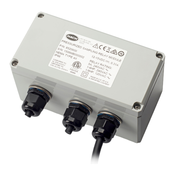
- Page 3 Table of contents Specifications on page 3 Operation on page 18 General information on page 3 Maintenance on page 18 Installation on page 7 Replacement parts on page 19 Specifications Specifications are subject to change without notice. Specification Details Dimensions (L x W x D) 160 x 80 x 86 mm (6.30 x 3.15 x 3.39 in.) Enclosure NEMA 4X, IP66, indoor or outdoor use...
- Page 4 Use of hazard information D A N G E R Indicates a potentially or imminently hazardous situation which, if not avoided, will result in death or serious injury. W A R N I N G Indicates a potentially or imminently hazardous situation which, if not avoided, could result in death or serious injury.
- Page 5 residential area is likely to cause harmful interference, in which case the user will be required to correct the interference at their expense. The following techniques can be used to reduce interference problems: 1. Disconnect the equipment from its power source to verify that it is or is not the source of the interference.
- Page 6 Figure 2 System overview 1 User-supplied equipment 6 Motorized ball valve 2 Junction box 7 Pressure relief valve 3 Pressurized sampling relay module 8 Pressure reducer/regulator 4 AS950 controller 9 Reduced-pressure sample line 5 Sample intake is higher than the ball valve 10 High-pressure sample line Product components Make sure that all components have been received.
- Page 7 Figure 3 Product components 1 Pressurized relay module with auxiliary cable 2 Mounting screws, 6 x 0.75 inch tapping (4x) User-supplied equipment Refer to Figure 2 on page 6 for an overview of the plumbing, mechanical and electrical parts that must be supplied by the user.
- Page 8 Remove the cover Remove the cover as shown in the illustrated steps that follow. Mounting Attach the module to a flat surface. The mounting surface must hold a minimum of 4 times the weight of the equipment. Make sure that the module is sufficiently near the sampler to easily connect or disconnect the cable to the sampler.
- Page 9 Figure 4 Mounting locations on the sampler English 9...
- Page 10 Electrical installation D A N G E R Multiple hazards. Only qualified personnel must conduct the tasks described in this section of the document. D A N G E R Electrocution hazard. Always remove power to the instrument before making electrical connections. W A R N I N G Electrical shock hazard.
- Page 11 Figure 5 High-voltage relay 1 Length of the removed cable jacket 4 TB2, NC (normally closed) 2 TB2, C (common) 5 Cable tie 3 TB2, NO (normally open) 6 High-voltage cable to junction box Table 2 TB2 terminal block description Connects to VAC mains When enabled, the ball valve connects When enabled, the ball valve...
- Page 12 Connect to the sampler Connect the cable from the module to the AUX I/O port on the sampler. Refer to Figure Figure 6 Connect to the sampler Optional connections Wiring for flow pacing C A U T I O N Electric shock hazard.
- Page 13 4. If more than 25.4 mm (1 inch) of the cable jacket is removed, install a plastic wire tie around the wires. Install the wire tie at a maximum distance of 19 mm (0.75 inch) from the terminal. Refer to Figure 5.
- Page 14 Figure 9 Externally-powered 4–20 mA transmitter 1 Low-voltage block (TB1) 3 Pulse/mA input terminal (+) 2 Common terminal (–) 4 4–20 mA transmitter Figure 10 Sampler controller-powered loop 1 Low-voltage block (TB1) 3 12/15 VDC terminal (+) 2 Pulse/mA input terminal (–) 4 4–20 mA transmitter Wiring for sampler program control C A U T I O N...
- Page 15 6. Install the cover. Make sure that the screws are tight to keep the environmental rating of the enclosure. 7. Refer to the user documentation to set up sampler program control. Figure 11 Wiring for sampler program control 1 Length of the removed cable jacket 4 Shield/drain terminal 2 Liquid level terminal 5 Cable tie...
- Page 16 TB1 terminal block description Refer to Table 3 for descriptions of the low-voltage TB1 terminals. Table 3 TB1 terminal block description Pin/signal Description Rating Special output Not used. Do not connect to this pin. — Liquid level Sends a signal to the sampler Termination (pulled high): internal +5 V supply through controller to start or continue a an 11 kΩ...
- Page 17 Table 3 TB1 terminal block description (continued) Pin/signal Description Rating Common AS950 power supply negative return. When the AS950 sampler is powered — by an AC/DC converter, this pin connects to earth ground. Shield/drain The shield is a connection to earth The shield is not a safety ground.
- Page 18 Figure 12 AWRS compartment drain 1 Center cable slot 2 Compartment heater Operation Configure the sampler Configure the sampler controller for pressurized sampling. When pressurized sampling is selected, the liquid detector is disabled. 1. Go to Hardware Setup. 2. Select AUX and I/O Port. 3.
- Page 19 W A R N I N G Biological hazard. Obey safety handling protocols and wear all of the personal protective equipment required when handling an instrument that may have come in contact with biological hazardous materials. Wash and decontaminate the instrument with a disinfectant soap solution and rinse with hot water before maintenance or shipping.
- Page 20 Description Item no. Fuse, 0.25 A, 250 V, 5 x 20mm 6681000 Mounting screws, 6 x 0.75 inch tapping 4481800 20 English...
- Page 22 Tel. +49 (0) 2 11 52 88-320 SWITZERLAND Fax (970) 669-2932 Fax +49 (0) 2 11 52 88-210 Tel. +41 22 594 6400 orders@hach.com info@de.hach.com Fax +41 22 594 6499 www.hach.com www.de.hach.com © Hach Company/Hach Lange GmbH, 2015. All rights reserved. Printed in U.S.A.
Need help?
Do you have a question about the 8520600 and is the answer not in the manual?
Questions and answers