
Related Manuals for Hach Lange CL17


Summary of Contents for Hach Lange CL17
- Page 1 DOC023.52.80034 CL17 Chlorine Analyzer USER MANUAL 02/2014, Edition 9 © Hach Company, 2000, 2001, 2004, 2008, 2009-2011, 2013, 2014. All rights reserved. Printed in the U.S.A./Germany...
-
Page 3: Table Of Contents
Table of Contents Section 1 Specifications ........................3 Section 2 General information ......................5 2.1 Safety information ........................5 2.1.1 Use of hazard information....................5 2.1.2 Precautionary labels ......................5 2.2 General product information ......................6 2.2.1 Instrument description......................6 2.2.2 Method of analysis ...................... - Page 4 Table of Contents 6.2.4 Replace the sample conditioning filter ................44 6.2.5 Reagent spill clean up .......................44 Section 7 Troubleshooting ......................45 7.1 Troubleshooting guide........................45 7.2 System alarms..........................46 7.3 System warnings ........................47 Section 8 Parts and accessories ....................49 Section 9 Contact information .......................51 Section 10 Certification ........................53...
-
Page 5: Section 1 Specifications
Wall mount Instrument shipping weight 10.49 kg (23 lb) Hach Company warrants its products to the original purchaser against any Warranty defects that are due to faulty material or workmanship for a period of one year from the date of shipment unless otherwise noted in the product manual. -
Page 6: Specifications
Alarm relay outputs point alarms (high or low) or as a system warning indicator or a system alarm indicator. ® Optional external outputs Hach AquaTrend Network Interface Environmental Storage temperature range -40 to 60 °C (-40 to 140 °F) Operating temperature range 5 to 40 °C (41 to 104 °F) -
Page 7: Section 2 General Information
Section 2 General information The information in this manual has been carefully checked and is believed to be accurate. However, the manufacturer assumes no responsibility for any inaccuracies that may be contained in this manual. In no event will the manufacturer be liable for direct, indirect, special, incidental or consequential damages resulting from any defect or omission in this manual, even if advised of the possibility of such damages. -
Page 8: General Product Information
The CL17 analyzer can be purchased with a Hach Network Interface Card which allows ® the CL17 to display its readings on an AquaTrend display or allows data to be sent to a PC via a Serial Interface Module. -
Page 9: Method Of Analysis
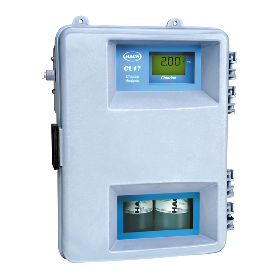
General information Figure 1 Chlorine analyzer 2.2.2 Method of analysis Free available chlorine (hypochlorous acid and hypochlorite ions) oxidizes the DPD indicator reagent at a pH between 6.3 and 6.6 to form a magenta-colored compound. The depth or intensity of the resulting color is proportional to the concentration of chlorine in the sample. -
Page 10: Theory Of Operation
General information 2.2.3 Theory of operation The analyzer is designed to capture and analyze a portion of the sample every 2.5 minutes. The sample portion is captured in the colorimeter measuring cell where the blank absorbance is measured. Measurement of sample blank absorbance allows compensation for any turbidity or natural color in the sample, and provides an automatic zero reference point. -
Page 11: Section 3 Installation
Section 3 Installation DANGER Electrocution and fire hazard. Only qualified personnel should conduct the tasks described in this section of the manual. 3.1 Unpack the instrument Remove the analyzer from its shipping carton and inspect it for any damage. Verify that the Installation Kit, Cat. - Page 12 Installation Figure 2 CL17 instrument dimensions (1 of 3) Air purge quick connect Power connections .25 O.D. Polyethylene Tubing, (4743800) Relay / alarm contact connections 4 x ¼” recommended mounting bolt Network and 4-20 mA connections...
- Page 13 Installation Figure 3 CL17 instrument dimensions (2 of 3)
-
Page 14: Plumbing Connections
Installation Figure 4 CL17 instrument dimensions (3 of 3) Overflow drain, recommended .50 I.D. tubing Sample inlet quick connect .25 O.D. Polyethylene tubing (4743800) .50 I.D. drain tube sample Plumbing connections Note: The sample drain contains analysis wastes, which include both sample and chemical reagents. -
Page 15: Installing The Sample Line
Installation Figure 5 Plumbing connections (bottom view) Front of instrument Sample drain. Instrument drain fitting is sized for ½ in. ID flexible tubing Enclosure drain Sample inlet. Quick connect fitting for ¼ in. O.D. tubing 3.5 Installing the sample line Selecting a good, representative sampling point is important for optimum performance of the instrument. -
Page 16: Sample Conditioning
Installation Figure 6 Sample line location in the process stream Poor Sediment (typical) Poor Good Air (typical) Best 3.6 Sample conditioning All samples are “conditioned” using the single-sample, basic sample conditioning kit shipped with each analyzer. The kit eliminates large particles using a 40-mesh strainer. The ball valve on the raw sample inlet line may be used to control the amount of bypass flow that is delivered to the filter. -
Page 17: Use The Sample Conditioning Kit
Installation 3.6.2 Use the sample conditioning kit Assemble the head height regulator (stand-pipe) and filter as shown in Figure 7. Make sure the sample pressure to the sample conditioning is between 1.5 and 75-psig for proper operation. 1. Set flow by adjusting the ball valve (item 18, in Figure 7). - Page 18 Installation Figure 7 Sample conditioning kit...
- Page 19 Installation Table 1 Sample Conditioning Parts List (refer to Figure Item Description Catalog Number Clamp, Conduit Hanger, 1-inch 47349-00 Coupling, 1-inch, SCH 40, PVC pipe 54175-00 Coupling, ½-inch FPT x ½ FPT PVC 54176-00 Fitting, Reduce Bushing, PVC, Hex 23002-00 Fitting, Stem Adapter, ½-inch O.D., ¼...
-
Page 20: Optional Air Purge
Installation Optional air purge Air purge may be necessary if the analyzer is located in an environment with high humidity and/or caustic vapors. The goal is to maintain a slight positive pressure in the instrument with dry instrument air. The air purge connection is located on the left side of the instrument enclosure. To connect an air supply, remove the plug in the quick connect fitting then connect ¼-inch poly tubing by pushing the tubing into the fitting. -
Page 21: Power Connections
Installation 3.8.1 Power connections DANGER Electrocution hazard. Only qualified personnel should conduct the tasks described in this section of the manual. Connect equipment in accordance with national, state and local electrical codes. Power connections are made at the terminal strip located in the left side of the electrical compartment and are accessible when the customer access cover is opened. -
Page 22: Wiring The Instrument
Installation Additionally, electrical and instrumentation standards require a local means of removing power from the product. The instrument is supplied with a power on/off switch that is located inside the instrument enclosure. To remove relay power from the instrument, an external customer-supplied 5A fused switch or a 5A breaker is required. -
Page 23: Voltage Selection For Alternate Voltage Operation
Installation Figure 11 Customer connections to analyzer Relays AC power: 100-115/230 VAC, 50/60 Hz, 90 VA fused at 2.50A Recorder Figure 12 Power connections A method to remove power from the relays locally must Since the ON/OFF switch can be accessed without the be available in case of an emergency or for servicing the use of a tool an external switch is not required for instrument. -
Page 24: Alarm Connections
Installation Figure 13 Voltage selector switch and fuse replacement Voltage selection switch (SW1). Factory set at 115V. Hot / Black Ø1 Fuses (F1, F2) (T, 2.5A, 250V) Neutral / White Ø2 3.8.4 Alarm connections CAUTION Fire hazard. Current to the relay contacts must be limited to 5 amps resistive. A method to remove power from the relays locally must be available in case of an emergency or for servicing the product. -
Page 25: Recorder Output Connections
Installation Figure 14 Proper wire preparation and insertion Strip ¼ in. of insulation Seat insulation against connector with no bare wire exposed. Figure 15 Alarm connections Current to the relay contacts must be limited to 5 amps. J2 alarm connections terminal block: Terminal 1 = COM; Terminal 2 = NO;... -
Page 26: Install The Pump/Valve Pinch Plate
Installation 5. Remove the connector from the instrument. Refer to Figure 16 on page 24for connector position. 6. Insert the wire ends into the connector (refer to the table below) until the insulation seats against the connector as shown in Figure 14. - Page 27 Installation 4. Install the two screws through the pinch plate and into the pump/valve module. Secure the pinch plate by turning the screws in small increments moving from one screw to the other so that the plate is drawn down evenly. Tighten until the plate is seated against the pump/valve module.
- Page 28 Installation Figure 18 Aligning the pump/valve module pinch plate Align pinch plate with pump/valve module Install screws. (Advance the screws in small increments moving from one screw to the other so that the plate is drawn down evenly.)
-
Page 29: Section 4 System Startup
Section 4 System Startup CAUTION Chemical exposure hazard. To familiarize yourself with handling precautions, dangers and emergency procedures, always review the Material Safety Data Sheets prior to handling containers, reservoirs, and delivery systems that contain chemical reagents and standards. Protective eye wear is always recommended when contact with chemicals is possible. -
Page 30: Install The Stir Bar
System Startup 4.2 Install the stir bar A small stir bar for the sample cell in the colorimeter assembly is included in the installation kit furnished with the instrument. The stir bar must be installed for the instrument to operate properly. Install the stir bar as follows: Note: Make sure the stir bar drops down into the colorimeter and remains in the colorimeter. -
Page 31: Supply The Sample
System Startup 4.3 Supply the sample Note: Make sure the pressure plate is securely attached to avoid backflow of the sample into the reagents. Start sample flow through the instrument by opening the supply valve (item 19 in Figure 7 on page 16). - Page 32 System Startup...
-
Page 33: Section 5 Operation
Section 5 Operation 5.1 Keypad and display information The instrument display defaults to normal Concentration Measurement Mode unless keys are pressed to change it. Table 5 shows the functions for each key. MENU mg/L EXIT ENTER Chlorine Figure 20 Analyzer keypad and display Table 5 Keypad Description Number... -
Page 34: Instrument Menu Structure
Operation 5.2 Instrument menu structure The major menus in the CL17 Analyzer consist of , and ALARMS RECRDR MAINT SETUP Press the keys to access the menus. The sections below give DOWN ARROW information on the functions of each of the menus and the submenus within them. 5.2.1 Setup menu Day-to-day analyzer functions are accessed from the menu. -
Page 35: Alarm Setup
Operation Table 6 Setup menu options Menu option Description Press to momentarily turn the relays off, then sequentially turn on ALARM1 and ALARM 2. ENTER RELAY TEST Automatically clears both alarms to complete the test. Momentarily displays the last Reference A/D counts. SAMPLE Momentarily displays the last Sample A/D counts. -
Page 36: Set The Recorder Output Span
Operation Perform the procedure below to assign functions to AL1 or AL2: 1. Press the key. will be displayed. MENU ALARMS 2. Press to select . The screen will display AL1 (or AL2), and either the ENTER ALARMS alarm set point (HI or LO), SA (System Alarm), or SW (System Warning). 3. -
Page 37: Change To 0 To 20 Ma Output Range
Operation Adjust the recorder output minimum and maximum values using the analyzer keypad: 1. Press the key. MENU 2. Scroll to menu and press . The display will show and a mg/L RECR DR ENTER REC LO reading. Move to REC HI ON SYSTEM ALARM 3. -
Page 38: Calibration
Operation 5.3 Calibration The CL17 Chlorine Analyzer is factory calibrated. A built-in electronic curve is preprogrammed into the instrument. This instrument does not require recalibration unless specified by your regulatory agency for compliance reporting purposes. If you are required to do a two-point calibration or if your sample stream chlorine concentration is typically less than 0.5 mg/L, follow the instructions in section 5.3.1. -
Page 39: Calibration By Comparison
Operation 8. Press and edit the value. Press again to accept the value.The ENTER ENTER measured value will be forced to the entered value. Press the key three times to EXIT return to normal display mode. 9. Remove the standard and restore sample flow to the analyzer. The instrument is now calibrated. - Page 40 Operation...
-
Page 41: Section 6 Maintenance
Section 6 Maintenance DANGER Multiple hazards. Only qualified personnel should conduct the tasks described in this section of the manual. CAUTION Chemical exposure hazard. To familiarize yourself with handling precautions, dangers and emergency procedures, always review the Material Safety Data Sheets prior to handling containers, reservoirs, and delivery systems that contain chemical reagents and standards. -
Page 42: Replace The Analyzer Tubing
Maintenance 6.1.3 Replace the analyzer tubing Remaining tubing in the analyzer should be replaced annually. The maintenance kit is available with the tubing harnesses assembled (6868800) or unassembled (6868900) If you have ordered the unassembled maintenance kit, use Figure 21 Table 7 on page 41 to determine the tubing lengths and positions. -
Page 43: Unscheduled Maintenance
Maintenance Table 7 Replacement Tubing Lengths for Figure 21 Item Description Length (Qty) From... To... Item Number 1/8" ID, 1/4" OD 4.5 inches (1) Pump Body Out Colorimeter 43293-00 1/32" ID, 3/32" OD 7.0 inches (2) Pump Body Out Y-Fitting 44253-00 1/16"... -
Page 44: Clean The Instrument Enclosure
Maintenance 6.2.2 Clean the instrument enclosure With the enclosure securely latched, use a soft cloth and a mild detergent to wipe the outside of the enclosure. Do not allow moisture to enter the enclosure. 6.2.3 Clean the colorimeter The colorimeter measuring cell may collect sediment or develop a film growth on the inside walls. - Page 45 Maintenance Figure 22 Removing the stir bar Remove the plug from the top hole of the colorimeter. Colorimeter assembly Gently insert a straightened paper clip into the hole at the top of the colorimeter and slowly pull out the stir bar.
-
Page 46: Replace The Sample Conditioning Filter
Maintenance Figure 23 Cleaning the colorimeter Remove the plug from the top hole of the colorimeter Colorimeter assembly Gently scrub the inside of the colorimeter with a cotton-tipped swab 6.2.4 Replace the sample conditioning filter To insert the filter into the housing: 1. -
Page 47: Section 7 Troubleshooting
Section 7 Troubleshooting In the event the instrument should malfunction, the following troubleshooting guide may be used to help isolate the problem. Please contact the nearest Service Center for assistance or shipping instructions if the instrument must be returned. 7.1 Troubleshooting guide Table 9 supplies troubleshooting information for the instrument. -
Page 48: System Alarms
EE Error Inability to write to the EE ROM EE ERROR to be replaced. Call Hach Service. Press the key to restart the instrument. If the EXIT Reference measurement = 0 problem recurs, there is a problem with the A/D counts colorimeter. -
Page 49: System Warnings
Troubleshooting 7.3 System warnings Recall active warnings using the function in the alarm menu. To clear RECALL WARNINGS the warnings use the function in the alarm menu. CLEAR WARNINGS Table 11 System warnings Alarm Display and Warning What the Alarm Indicates Resolution Instrument Indication Power failed. - Page 50 Troubleshooting...
-
Page 51: Section 8 Parts And Accessories
Section 8 Parts and accessories Description Quantity Item Number Circuit Board Assembly, main each 5440400 Colorimeter Module each 6867000 Colorimeter Plug each 6868500 Connector for Alarm or Recorder each 4458200 Cam/Coupler Assembly each 5445200 Follower Block, Reagent each 4274100 Follower Block Sample each 4274200 Fuse, (T, 2.5 A, 250V) UL/CSA/CE accepted, 2 needed... - Page 52 Parts and accessories...
-
Page 53: Section 9 Contact Information
HACH Company Repair Service in Canada: Latin America, the World Headquarters Repair Service in the Caribbean, the Far East, Hach Sales & Service United States: Indian Subcontinent, Africa, P.O. Box 389 Canada Ltd. Europe, or the Middle East: Loveland, Colorado... -
Page 54: Contact Information
Contact information HACH LANGE D.O.O. ΗΑCH LANGE E.Π.Ε. HACH LANGE MAROC HACH LANGE D.O.O. SARLAU Fajfarjeva 15 Αυλίδος 27 Ivana Severa bb SI-1230 Domžale GR-115 27 Αθήνα Villa 14 – Rue 2 Casa HR-42 000 Varaždin Tel. +386 (0)59 051 000 Τηλ. -
Page 55: Section 10 Certification
10.1 FCC PART 15, Class "A" Limits Supporting test records by Hewlett Packard, Fort Collins, Colorado Hardware Test Center (A2LA # 0905-01) and certified compliance by Hach Company. This device complies with Part 15 of the FCC Rules. Operation is subject to the following... - Page 56 Certification...
-
Page 57: Appendix A Network Interface Card
Modules are not supported. Refer to the AquaTrend Interface Instruction Manual for complete details on configuring the Hach network. 1. Route a Hach-approved network cable to the CL17 Analyzer. Route the network cable through the middle wiring access hole in the CL17 housing. (This hole is also used for routing Recorder output wiring.) Use appropriate hardware to maintain the... -
Page 58: Adding The Measurement To A Channel
Network Interface Card A.2 Adding the measurement to a channel The measurement from the CL17 Analyzer must be associated with a channel on the AquaTrend Interface so the measurement will be shown on the AquaTrend display. Attach the measurement to a channel as follows: 3. -
Page 59: Manually Polling Data
Measurement and alarm data from the CL17 Analyzer can be converted to a Modbus protocol using the Hach MOD I/O Module. The data can then be polled by any Modbus Master Device (PLC/DCS) including the Hach OPC server/OPC data logger. Refer to the MOD I/O Module Manual for additional information. - Page 60 Network Interface Card...
Need help?
Do you have a question about the Lange CL17 and is the answer not in the manual?
Questions and answers