Hach Surface Scatter 7 sc User Manual
Turbidimeter
Hide thumbs
Also See for Surface Scatter 7 sc:
- Instruction sheet (6 pages) ,
- User manual (64 pages) ,
- User manual (40 pages)

Subscribe to Our Youtube Channel
Related Manuals for Hach Surface Scatter 7 sc


Summary of Contents for Hach Surface Scatter 7 sc
- Page 1 Catalog Number DOC026.53.00769 ® Surface Scatter 7 sc Turbidimeter USER MANUAL Edition 2 November 2006...
- Page 2 HTTC Regional Workshops and Custom Training Hach offers world-class hands-on training for laboratory analysis and online analyzers at regional locations convenient to you so you can learn how to Be Right and Stay Right. Hach’s regional training workshops cover topics relevant to applications in drinking water, wastewater, and industry.
- Page 5 Catalog Number DOC026.53.00769 ® Surface Scatter 7 sc Turbidimeter USER MANUAL Edition 2 November 2006 © Hach Company, 2006. All rights reserved. Printed in the U.S.A. te/kt...
- Page 6 Visit us at www.hach.com...
-
Page 7: Table Of Contents
2.1.2 Precautionary labels ......................9 2.2 General product information ..................... 10 2.2.1 Instrument description ...................... 10 2.2.2 Surface Scatter 7 sc High Sample Temperature ............. 13 Section 3 Installation ......................15 3.1 Basic installation overview ......................15 3.2 Unpacking the instrument ......................15 3.3 Mechanical installation ...................... - Page 8 Table of Contents Section 7 Troubleshooting ....................47 7.1 Error Codes ..........................47 7.2 Warnings ...........................47 7.3 Event codes ..........................49 7.4 Data log .............................50 Section 8 Replacement parts and accessories ..............51 8.1 Replacement parts ........................51 8.2 Accessories ..........................51 Section 9 How to order ......................53 Section 10 Repair service .....................54 Section 11 Limited warranty ....................55 Section 12 Certification ......................57...
-
Page 9: Section 1 Specifications
Mandatory before calibration Recommended cleaning Optional before verification intervals Mandatory upon verification failure English (default), German, French, Spanish, Italian, Swedish, Polish, Korean, Languages Chinese, Japanese Installation environment Indoor Primary compliance USEPA 180.1; Hach Method 8195; ASTM D 6698; Standard Methods 2130B method... - Page 10 Specifications Figure 1 Maximum ambient temperature vs. probe load Table 1 sc100 controller capacity Controller operating temperature (°C) Power available (watts) Controller capacity 1 SS7 sc plus 5 watts for other devices 1 SS7 sc plus 4 watts for other devices Out of power range for SS7 sc...
-
Page 11: Specifications
Specifications Figure 2 Maximum ambient temperature vs. probe load Table 2 sc1000 controller capacity Controller operating temperature (°C) Power available (watts) Controller capacity 2 SS7 sc plus 15 watts for other devices 2 SS7 sc plus 11 watts for other devices 1 SS7 sc plus 13 watts for other devices Table 3 sc1000 component power consumption Power consumption (watts) - Page 12 Visit us at www.hach.com...
-
Page 13: Section 2 General Information
Section 2 General information 2.1 Safety information Please read this entire manual before unpacking, setting up or operating this equipment. Pay attention to all danger and caution statements. Failure to do so could result in serious injury to the operator or damage to the equipment. To ensure that the protection provided by this equipment is not impaired, do not use or install this equipment in any manner other than that specified in this manual. -
Page 14: General Product Information
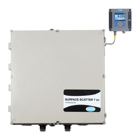
General information 2.2 General product information 2.2.1 Instrument description ® The Surface Scatter 7 sc (SS7 sc) Turbidimeter is a sensitive, continuous-monitoring instrument designed for measuring turbidity in fluids. The instrument design is based on the nephelometric principle, where light scattered by particles suspended in the fluid is measured to determine the relative amount of particulate matter in the fluid. - Page 15 General information 2.2.1.1 Controller The SS7 sc and SS7 sc-HST operate in conjunction with an sc controller platform. The controller enclosure houses the keypad, display, microprocessor board and power supply components. Operating controls and indicators are on the controller. The controller is used to program the instrument for turbidity level alarm set points and to perform diagnostic self-tests and programming operations.
- Page 16 General information Figure 4 SS7 sc components Detector assembly (Cat. No. 71221-00) Bulkhead fitting, 1-in. NPT (Cat. No. 40355-00) Light source assembly (Cat. No. 45004-00) Bulkhead fittings, ¾-in. NPT (Cat. No. 40311-00) To sc controller platform Turbidimeter body (Cat. No. 45002-00) Cord grip (Cat.
-
Page 17: Surface Scatter 7 Sc High Sample Temperature
12 Reflected light 2.2.2 Surface Scatter 7 sc High Sample Temperature The Surface Scatter 7 sc High Sample Temperature Turbidimeter (SS7 sc-HST) has been designed for high sample temperature. The basic design and principle of operation are the same as the standard SS7 sc model. - Page 18 General information Figure 6 SS7 sc-HST components Flow multiplier Cord grip (Cat. No. 61287-01) ¾-in. hose Bulkhead fitting, 1-in. NPT (Cat. No. 40355-00) Threaded disk (Cat. No. 40299-00) with ¼-in. screw 10 Drain trap (Cat. No. 7858-11) Detector assembly (Cat. No. 71221-00) 11 1-in.
-
Page 19: Section 3 Installation
Section 3 Installation DANGER Only qualified personnel should conduct the tasks described in this section of the manual. The SS7 sc/sc controller product configuration is not intended for installation in hazardous locations. The tasks described in this section requires individuals to be technically knowledgeable of the associated dangers. -
Page 20: Mechanical Installation
Installation Figure 7 Installation kit items Formazin stock solution, 4000 NTU, 500 mL Washer, ¼ ID x 1.00 OD (4x) Brush, cylinder, size 2 Adapter, barb fitting, ¾” NPT to ¾” ID hose barb (2x) Calibration cup, SS7 sc Adapter, barb fitting, 1” NPT to 1” ID hose Light source alignment plate Nipple, ¾”... -
Page 21: Mounting The Ss7 Sc Or Ss7 Sc-Hst
Installation turbidimeter sensor must be mounted within six feet of the controller unless an extension cable is used. Maximum cable length is 9.6 m (31.5 ft). 3.3.3 Mounting the SS7 sc or SS7 sc-HST 1. To ensure proper performance, the sample unit must be level (Figure 9 on page 19). - Page 22 Installation Figure 8 SS7 sc and SS7 sc-HST installation drawing Door hinges (4x) Ball valve Flow multiplier (SS7 sc-HST only) ¾-in. NPT nipple Ventilator (2x) 1-in. NPTF bulkhead fitting Cable assembly 10 ¾-in. NPTF bulkhead fitting Enclosure door latch (4x) 11 Air purge fitting Drain trap (SS7 sc-HST only)
-
Page 23: Installing The Optional Heat Exchanger
Installation Figure 9 Instrument leveling Level 3.3.4 Installing the optional heat exchanger An optional heat exchanger (Cat. No. 48551-00) is available for the SS7 sc-HST (Figure 10 on page 20). The heat exchanger reduces sample temperatures that exceed the temperature requirements of the instrument. -
Page 24: Installing The 3-Way Ball Valves
Installation Figure 10 Heat exchanger dimensions 3.3.5 Installing the 3-way ball valves CAUTION Installation should be performed by qualified technical personnel to ensure adherence to all applicable electrical and plumbing codes. Refer to the Auto Flush Kit Instruction Sheet (Cat. No. 46692-88) for complete installation instructions. -
Page 25: Connecting Hydraulics
Installation Figure 11 Sampling techniques Poor Sediment (typical) Sampling line to sample unit Good Sample flow Best Air (typical) 3.5 Connecting hydraulics Note: When connecting the hydraulics to the bottom of the unit, hold the ¾-in. bulkhead adapters on the inside of the enclosure with the door open. The sample in, body drain and overflow drain are connected to the instrument as shown in Figure 5 on page... - Page 26 Installation Figure 12 SS7 sc-HST plumbing diagram Optional items 14 Sample unit Bubble trap 15 sc100 3-way ball valve (Auto Flush Kit) 16 Customer supplied power on/off switch box (NEMA 4X) required for agency compliance Cooling water to drain 17 Power in for sc controller platform Cooling water out 18 ¾-in.
- Page 27 Installation Figure 13 SS7 sc plumbing diagram Sample in Power in for the sc controller platform Flow control valve (recommended) 10 ¾-in. NPT nipple (supplied) ¾-in.NPT x ¾-in. ID Hose Adapter 11 Ball valve (supplied) (supplied with bubble trap) Bubble trap (optional) 12 ¼-in.
-
Page 28: Connecting The Air Purge
Installation 3.6 Connecting the air purge Air purge helps control condensation and corrosive vapors within the sample unit and is recommended. Use dry instrument air only. Figure 12 Figure 13 for installation details. 3.7 Electrical installation 3.7.1 Wiring safety information When making any wiring connections to the instrument, the following warnings and notes must be adhered to, as well as, any warnings and notes found throughout the individual installation... - Page 29 Installation Figure 14 Attaching the SS7 sc/SS7 sc-HST using the quick-connect fitting 3.7.2.2 Hard-wiring the SS7 sc to the sc100 controller Important Note: Refer to the sc100 or sc1000 controller manual for specific wiring requirements. 1. Disconnect power to the controller if powered. 2.
- Page 30 Installation Table 4 Wiring the SS7 sc at terminal block J5 Terminal number Terminal designation Wire color Data (+) Blue Data (–) White Service request No connection +12 V dc Brown Circuit common Black Shield Shield (gray wire in existing quick disconnect fitting) Figure 15 Hard-wiring the SS7 sc From SS7 sc Disconnect power...
-
Page 31: Section 4 System Startup
Section 4 System startup 4.1 General operation 1. Plug the SS7 sc/SS7 sc-HST into the unpowered controller by aligning the orientation tab on the cable connector with the channel in the controller connector. 2. Push in and turn the threaded collar to secure the connection. Tug gently to check the connection. - Page 32 Visit us at www.hach.com...
-
Page 33: Section 5 Operation
Section 5 Operation 5.1 Sensor setup When a sensor is initially installed, the sensor name will be displayed. To change the sensor name refer to the following instructions: 1. From the Main Menu, select SENSOR SETUP and confirm. 2. If multiple sensors are attached to the controller, choose SELECT SENSOR>SS7 SETUP and confirm. -
Page 34: Sensor Data Logging
The logs can be downloaded through the digital network port, service port or the IrDA port. DataCom (Cat. No. 59256-00 or download from www.hach.com) is needed for downloading logs to a computer. If the datalogging frequency is set to 15 minute intervals, the instrument can continue to store data for approximately six months. -
Page 35: Sensor Calibration And Verification
Periodic calibration with a formazin primary standard is recommended for best absolute accuracy. 5.5.2 Calibration The manufacturer recommends calibrating the Surface Scatter 7 sc instrument at least every three months or any time the light source is replaced or adjusted. If calibration is performed with a formazin standard, refer to section 5.5.2.1 on page... - Page 36 Operation 8. If no selection is made for a set period of time, the screen will prompt to remix the standard to avoid a change in the value of the standard. a. Open the SS7 sc and remix the standard. b.
- Page 37 Operation 7. Confirm to calibrate. When the calibration is completed successfully, the display will show GOOD CAL! and the new calibration gain value. Confirm to accept the calibration. 8. Follow the prompt and enter the initials of the user performing the calibration.
-
Page 38: Setting The Verification Baseline
Operation calibrated. Take a grab sample from the on-line instrument drain or sample inlet line and immediately measure its turbidity in the laboratory instrument. If the on-line instrument reading is off by more than 5%, use the calibration procedure detailed in section 5.5.2 on page 31 to input the new standard value. -
Page 39: Instrument Verification
Operation 6. Open the SS7 sc to remove the plate. Restart the sample flow and close the door. Confirm to return the instrument to measurement mode. Note: After confirmation of return to measurement mode, the instrument will equilibrate for 2 minutes before the output mode changes. Instrument measurements will show on the display, but the value will flash and a “OUT MODE WARN”... -
Page 40: Calibration And Verification History
Operation 9. When the displayed turbidity value is stable, confirm to select the measured reading. After confirming the reading: • GOOD VER! will be displayed if the verification is good, with an option to continue or to abort. Confirm to continue. Enter the operator initials and confirm. - Page 41 Operation 5. Confirm to view the previous calibrations. After scrolling through all 12 histories, the display will return to the calibration menu level. To view verification history: 1. From the Main Menu, select SENSOR SETUP and confirm. 2. If multiple sensors are attached to the controller, choose SELECT SENSOR>SS7 SETUP and confirm.
-
Page 42: Operating The Ss7 Sc-Hst
Operation 5.7 Operating the SS7 sc-HST • If condensation forms in the enclosure, increase the air pressure (and flow) by increasing the air pressure setting of the pressure regulator for the flow multiplier. • Make sure the bubble trap is working. Bubbles on the surface of the liquid will cause incorrect readings. -
Page 43: Section 6 Maintenance
Section 6 Maintenance DANGER Only qualified personnel should conduct the tasks described in this section of the manual. The nature of tasks described in this section of the manual requires individuals to be technically knowledgeable of the associated dangers. Burns, shock, eye damage, fire and chemical exposure may occur if this work is not done by qualified personnel. -
Page 44: Cleaning
Maintenance 6.3.1 Cleaning Sediment may collect in the turbidimeter body and on the overflow weir. Algae may also form. The turbidimeter body should be drained and flushed—on a schedule determined by visual inspection—to remove accumulated sediment. Algae can be removed with a large bottle brush and a sterilizing solution such as dilute chlorine bleach. - Page 45 Maintenance 5. Wipe the replacement lamp clean to remove any dust and fingerprints. Fingerprints left on the glass bulb can permanently damage the lamp. Install the lamp in the light source block. 6. Slide the notched spacer over the lamp cable with the notch away from the lamp base.
- Page 46 Maintenance Figure 17 Lamp replacement Lamp cable Spacer End plate Housing Notched spacer Light source assembly Back plate Lamp Base...
-
Page 47: Light Source Assembly Maintenance
Maintenance Figure 18 Alignment details Flat notch Light source assembly Alignment template Mounting screws Calibration cylinder Target area Turbidimeter body Adjust light source to align light beam in target area Install calibration cylinder and alignment template 6.4.2 Light source assembly maintenance No maintenance of the light source assembly is normally necessary beyond changing the lamp. -
Page 48: Detector Assembly Replacement
Maintenance Figure 19 Light source assembly Shield assembly (Cat. No. 45299-00) 10 Spacer, light source (Cat. No. 45039-00) Wavy washer (2x) (Cat. No. 45042-00) 11 Gasket (Cat. No. 45033-00) Medium aperture (Cat. No. 45044-00) 12 End plate (Cat. No. 45032-00) Large aperture (Cat. - Page 49 Maintenance 6. Remove the two screws securing the detector assembly to the wall of the SS7 sc enclosure. Remove the complete detector assembly (Figure 20, item 1). 7. Use the two screws removed in step to secure the new detector to the wall of the SS7 sc enclosure. Secure the cable with the cable clamps.
- Page 50 Maintenance Figure 20 Detector assembly replacement Detector assembly (Cat. No. 71221-00) Clamping fingers Light source assembly power connector Bushing Cable clamp Blunt object Detector assembly cable Strain relief...
-
Page 51: Section 7 Troubleshooting
Section 7 Troubleshooting 7.1 Error Codes Errors are indicated by a flashing measurement value and a flashing warning icon. Errors are defined in Table 1. From the Main Menu, select SENSOR DIAG and confirm. 2. If multiple sensors are attached to the controller, choose SELECT SENSOR>SS7 SETUP and confirm. -
Page 52: Troubleshooting
Troubleshooting Table 6 Warning Codes (continued) Warning Displayed Warning Definition/Resolution Number EXT FLASH FAIL External copy of the application code has failed. Self recovery should occur. INT FLASH FAIL Internal copy of the application code has failed. Self-recovery should occur. ENGLISH ONLY English only device driver file. -
Page 53: Event Codes
Troubleshooting Table 8 presents additional malfunctions which may not be recorded in the Event Log. Table 8 Additional malfunctions not recorded in the event log Symptom Possible cause Corrective action The calibration standard was either Verify the accuracy of calibration standards and calibrate Continuous underrange improperly prepared or was unstable at the instrument. -
Page 54: Data Log
Troubleshooting Table 9 Event log list (continued) Event Event # Data2 Data3 Data1 Baseline Serial Number Expected Operator AC update start — — — AC update done — — — AC update fail — — — AC internal fail — —... -
Page 55: Section 8 Replacement Parts And Accessories
Washer, ¼ ID x 1.00 OD (4x) 44173-00 Wall Mounting kit 44247-00 Light Source Shield Assemblies (2x) 45299-00 Detector Assembly 71221-00 Lamp Assembly, Surface Scatter 7 sc 45034-00 Manual DOC026.53.00769 Quick Reference Document DOC016.53.00769 Tubing Replacement Kit 46691-00 8.2 Accessories Cat. - Page 56 Visit us at www.hach.com...
-
Page 57: Section 9 How To Order
Brief description or model number • Quantity International customers Hach maintains a worldwide network of dealers and distributors. To locate the representative nearest you, send an e-mail to: intl@hach.com or contact: Hach Company World Headquarters; Loveland, Colorado, U.S.A. Telephone: (970) 669-3050; Fax: (970) 669-2932 Technical and customer service (U.S.A. -
Page 58: Section 10 Repair Service
Section 10 Repair service Authorization must be obtained from Hach Company before sending any items for repair. Please contact the Hach Service Center serving your location. In the United States: Hach Company Ames Service 100 Dayton Avenue Ames, Iowa 50010 (800) 227-4224 (U.S.A. -
Page 59: Section 11 Limited Warranty
In the event that a defect is discovered during the warranty period, Hach Company agrees that, at its option, it will repair or replace the defective product or refund the purchase price excluding original shipping and handling charges. - Page 60 Visit us at www.hach.com...
-
Page 61: Section 12 Certification
UL 61010A-1 Listed by ETL (cETLus safety mark) CSA C22.2 No. 61010.1 Certified by ETL (cETLus safety mark) Certified by Hach Co. to EN 61010-1 Amds. 1 & 2 (IEC1010-1) per 73/23/EEC, supporting test records by Intertek Testing Services. Immunity... - Page 62 EN 55011 (CISPR 11) Class “A” emission limits Canadian Interference-causing Equipment Regulation, IECS-003, Class A Supporting test records and compliance certification by Hach Company. This Class A digital apparatus meets all requirements of the Canadian Interference- Causing Equipment Regulations. Cet appareil numÈrique de la classe A respecte toutes les exigences du RËglement sur le matÈriel brouilleur du Canada.
- Page 63 Appendix A Modbus register Tag Name Register # Data Type Length Description TURB 40001 Float Measured turbidity value TURB INT 40003 Unsigned Integer Integer turbidity value TURB INT X 100 40004 Unsigned Integer Integer turbidity * 100 SENSOR NAME 40005 String Sensor name or location BUBBLE REJECT...
- Page 64 Visit us at www.hach.com...
- Page 65 Appendix B Theory of operation B.1 SS7 sc principle of operation The Surface Scatter 7 sc Turbidimeter is a sensitive and precise instrument designed to measure the light scattered by particles suspended in the sample fluid. The sample flows up through the turbidimeter body at a rate between 1 and 2 liters per minute (¼...
- Page 66 Visit us at www.hach.com...
Need help?
Do you have a question about the Surface Scatter 7 sc and is the answer not in the manual?
Questions and answers
HOW TO CONNECT THE PNEUMATIC VALVES?