Advertisement
Quick Links
Advertisement

Subscribe to Our Youtube Channel
Related Manuals for BDI LINEA 5801A


Summary of Contents for BDI LINEA 5801A
- Page 1 LINEA 5801(A)/5802(A) ™ SHELVING INSTRUCTION MANUAL LET’S GET STARTED. DESIGN MATTHEW WEATHERLY...
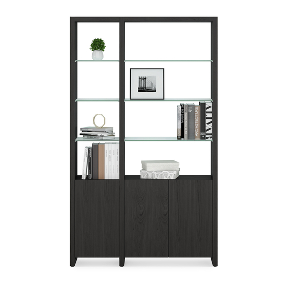
- Page 3 Congratulations on purchasing your Linea Shelving 5801(A) / 5802(A) from BDI. Your shelving has been designed to provide a lifetime of enjoyment. This manual will provide you with assembly instructions and other helpful information to ensure that you get the most out of your shelving.
- Page 4 Unpack and identify the parts listed below. Note that some components are shipped inside the cabinet. The assembly workspace should be a non-marring surface such as carpet. For missing hardware pieces, please contact BDI Customer Service at customerservice@bdiusa.com. Do not use power tools for the assembly of this product.
- Page 5 HARDWARE AND COMPONENTS Holes on 1 side Holes on 2 sides PART # PART # DESCRIPTION End Panel DESCRIPTION Inner Panel QUANTITY 2 per Base Unit QUANTITY 1 per extension unit 5801/5801A 5801/5801A 5802/5802A 5802/5802A PART # PART # DESCRIPTION DESCRIPTION Top Panel Cabinet...
- Page 6 HARDWARE AND COMPONENTS HARDWARE AND COMPONENTS Wall Mounting Kit PART # PART # PART # DESCRIPTION DESCRIPTION DESCRIPTION Wall Bracket Cabinet Bracket Fastener Screw QUANTITY QUANTITY QUANTITY PART # PART # PART # DESCRIPTION DESCRIPTION DESCRIPTION Sheetrock Anchor Plaster/Block Anchor Bracket Screw QUANTITY QUANTITY...
- Page 7 SINGLE OR MULTIPLE UNITS Linea can be configured as stand-alone units or multiple combinations of narrow and wide units. GO TO PAGE 8 GO TO PAGE 20 5801 5802 5801/5802 + 5801A/5802A or other multi-unit combinations NEED ASSISTANCE? customerservice@bdiusa.com BDIUSA.COM | 7...
- Page 8 ASSEMBLY STEP 1. ATTACH CABINET BLOCKS TO END PANELS Attach 1 (C3) Cabinet Block to each (C1) End PART/DESCRIPTION Panel using (H1) Screws and (T2) Hex Driver. T2-HEX DRIVER H1-SCREW C3-CABINET BLOCK Lower End 8 | BDIUSA.COM LINEA 5801(A) / 5802(A)
- Page 9 STEP 2. INSTALL CAMS AND DOWELS ASSEMBLY Find the sets of 3 holes near the top edge of the PART/DESCRIPTION (C1) Side Panels. Screw (H2) Cam Bolts into the threaded holes using (T1) Phillips Screwdriver and T1-PHILLIPS push (H3) Wooden Dowels into the outer holes. SCREWDRIVER H2-CAM BOLT Lower End...
- Page 10 ASSEMBLY STEP 3. INSERT BARREL NUTS Insert 4 (H4) Barrel Nuts into the holes on the PART/DESCRIPTION top of the (C4) Top Panel, making sure that the hole on the side of the barrel nuts align with the holes on the edges of the panel. H4-BARREL NUT Align hole 5801...
- Page 11 STEP 4. ATTACH TOP PANEL TO SIDE PANEL ASSEMBLY Attach (C4) Top Panel to (C1) End Panel by PART/DESCRIPTION sliding dowels and cam bolts into the holes on the edge of (C4) Top Panel. If cams don’t go into T1-PHILLIPS barrel nuts, check to make sure the barrel nut is SCREWDRIVER aligned with the side hole and make sure the set...
- Page 12 ASSEMBLY STEP 5. ATTACH SECOND END PANEL Attach the next (C1) End Panel to the other side of PART/DESCRIPTION (C4) Top Panel by sliding dowels and cams into the holes on the side of (C4) Top Panel. Tighten barrel T1-PHILLIPS nuts using (T1) Phillips Screwdriver.
- Page 13 STEP 6. ATTACH CABINET TO END PANELS ASSEMBLY Making sure the bottom of the cabinet is against PART/DESCRIPTION the (C3) Cabinet Blocks, carefully open the cabinet door and attach the (C5) Cabinet to (C1) End Panels using 8 (H1) Screws and tighten T2-HEX DRIVER with (T2) Hex Driver.
- Page 14 2 PERSON TASK ASSEMBLY STEP 7. STAND UP / WALL CONNECTION With help from another person, carefully stand the cabinet onto its base. Carefully walk it into position. Attaching your Linea shelving to the wall is required to ensure your safety. Use painter’s tape to mark both upper back corners of the unit, as shown.
- Page 15 STEP 8. WALL CONNECTION (continued) ASSEMBLY Move the cabinet to the side. Place (H5) Wall PART/DESCRIPTION Brackets on the wall (flush with top and 1/4" (7mm) away from the edge) and mark hole locations on the wall using a pencil. Drill holes at H5-WALL BRACKET these locations for wall inserts.
- Page 16 2 PERSON TASK ASSEMBLY STEP 9. WALL CONNECTION (continued) Re-position your Linea cabinet in front of the PART/DESCRIPTION (H5) Wall Brackets. Stand on a step ladder and slide (H6) Cabinet Brackets down into the slot in (H5) Wall Brackets and tighten using (H10) Bracket T2-HEX DRIVER Screws and (T2) Hex Driver.
- Page 17 STEP 10. INSTALL SHELVES AND LEVEL ASSEMBLY Attach 16 (H11) Shelf Pins into the threaded holes PART/DESCRIPTION using a (T1) Phillips Screwdriver—choose preferred interior shelf height. Install (C6) Outer Glass T1-PHILLIPS Shelves on the shelf pins, tilting the glass slightly SCREWDRIVER to avoid hitting side panels.
-
Page 18: Fine Tuning
FINE TUNING CHOOSE DOOR POSITION The door on your Linea 5801 Cabinet can be PART/DESCRIPTION attached to the opposite side (if desired), allowing the door to swing to the right. Remove the 2 screws T1-PHILLIPS holding each hinge plate to the side of the cabinet SCREWDRIVER using (T1) Phillips Screwdriver and flip the door (top becomes bottom) and attach to the threaded... - Page 19 CONFIGURATIONS Endless Possibilities Linea can be configured in endless ways. Below are a few examples. Configurations up to 3 units wide may be assembled on the floor, stood up and carefully positioned. It is also possible to assemble 1 unit, stand it up, and add additional units to it. Every configuration requires 1 base unit and then additional units.
- Page 20 HARDWARE AND COMPONENTS HYBRID KIT Hybrid Assembly The following pages will show how to assemble a kit of 2 units shown below—which is a 5802 and a 5801A. Your configuration may differ, but the assembly method will be the same. End Panel End Panel Inner Panel...
- Page 21 STEP 1. ATTACH CABINET BLOCKS TO PANELS ASSEMBLY Attach (C3) Cabinet Blocks to a (C1) End Panel PART/DESCRIPTION and a (C2) Inner Panel using (H1) Screws and (T2) Hex Driver. T2-HEX DRIVER H1-SCREW 4 per unit C3-CABINET BLOCK 2 per unit NEED ASSISTANCE? customerservice@bdiusa.com BDIUSA.COM | 21...
- Page 22 ASSEMBLY STEP 2. INSTALL CAMS AND DOWELS Find the sets of 3 holes near the top edge of the PART/DESCRIPTION (C1) End Panel and (C2) Inner Panel. Screw (H2) Cam Bolts into the threaded holes using (T1) T1-PHILLIPS Phillips Screwdriver and push (H3) Wooden SCREWDRIVER Dowels into the outer holes.
- Page 23 STEP 3. INSERT BARREL NUTS ASSEMBLY Insert 4 (H4) Barrel Nuts into the holes on the PART/DESCRIPTION top of the (C4) Top Panel, making sure that the hole on the side of the barrel nuts align with the holes on the edges of the panel. H4-BARREL NUT Align hole 5801...
- Page 24 ASSEMBLY STEP 4. ATTACH TOP PANEL TO PANELS Attach (C4) Top Panel to (C1) End Panel and PART/DESCRIPTION (C2) Inner Panel by sliding dowels and cam bolts into the holes on the edge of (C4) Top Panel. T1-PHILLIPS If cams don’t go into barrel nuts, check to make SCREWDRIVER sure the barrel nut is aligned with the side hole and make sure the set screw is loosened before...
- Page 25 STEP 5. ATTACH CABINET ASSEMBLY Making sure the bottom of the cabinet is against PART/DESCRIPTION the (C3) Cabinet Blocks, carefully open the cabinet doors and attach the (C5) Cabinet to (C1) End Panels and (C2) Inner Panels using T2-HEX DRIVER 8 (H1) Screws per cabinet and tighten with (T2) Hex Driver.
- Page 26 2 PERSON TASK ASSEMBLY STEP 6. STAND UP / CONNECT TO WALL Painter’s tape 6A-1: Inline Against Wall 6A-2: Inline Against Wall Option A: With help from at least 1 other Option A: Attaching your Linea Cabinet to person, carefully stand the cabinets onto the wall is required to ensure your safety.
- Page 27 STEP 7. WALL CONNECTION (continued) ASSEMBLY Move the cabinet to the side. Place (H5) Wall PART/DESCRIPTION Brackets on the wall (flush with top and 1/4" (7mm) away from the edge) and mark hole locations on the wall using a pencil. Drill holes at H5-WALL BRACKET these locations for wall inserts.
- Page 28 2 PERSON TASK ASSEMBLY STEP 8. WALL CONNECTION (continued) Re-position your Linea cabinet in front of the PART/DESCRIPTION (H5) Wall Brackets. Stand on a step ladder and slide one (H6) Cabinet Bracket down into the slot in (H5) Wall Brackets and tighten using (H10) T2-HEX DRIVER Bracket Screws and (T2) Hex Driver.
- Page 29 STEP 9. ATTACH CABINET BLOCK(S) TO PANEL(S) ASSEMBLY Attach (C3) Cabinet Block to the next panel in PART/DESCRIPTION the series using (H1) Screws and (T2) Hex Wrench. Note: If you assemble the final unit in the series, T2-HEX DRIVER this will be a (C1) End Panel. If you are attaching additional units, this will be a (C2) Inner Panel.
- Page 30 ASSEMBLY STEP 10. INSTALL CAMS AND DOWELS Find the sets of 3 holes near the top edge of the PART/DESCRIPTION panel. Screw (H2) Cam Bolts into the threaded holes using (T1) Phillips Screwdriver and push T1-PHILLIPS (H3) Wooden Dowels into the outer holes. SCREWDRIVER H2-CAM BOLT 4 per unit...
- Page 31 2 PERSON TASK STEP 12. ATTACH TOP PANEL TO DIVIDER PANEL ASSEMBLY With help from at least 1 other person, carefully stand the top panel and end panel assembly onto its base and connect it to the (C2) Inner Panel by sliding the dowels and cam bolts into the holes on the edge of the (C4) Top Panel.
- Page 32 ASSEMBLY STEP 13. CONNECT TO WALL If this is the final unit in the series, follow steps 13–15 to connect to the wall. If you will be attaching additional units, skip to step 16. Use painter’s tape to mark at least 1 upper back corner of the last unit in the series, as shown. Painter’s tape Remove add on panel.
- Page 33 STEP 14. WALL CONNECTION ASSEMBLY Move the cabinet to the side. Place (H5) Wall PART/DESCRIPTION Brackets on the wall (flush with top and 1/4" (7mm) away from the edge) and mark hole locations on the wall using a pencil. Drill holes at H5-WALL BRACKET these locations for wall inserts.
- Page 34 2 PERSON TASK ASSEMBLY STEP 15. ATTACH TOP PANEL TO DIVIDER PANEL With help from at least 1 other person, carefully PART/DESCRIPTION stand the top panel and end panel assembly onto its base and connect it to the (C2) Inner Panel by sliding the dowels and cam bolts into the holes on T2-HEX DRIVER the edge of the (C4) Top Panel.
- Page 35 2 PERSON TASK STEP 16. INSTALL CABINET ASSEMBLY With the help of at least 1 other person, carefully slide the (C5) Cabinet onto the (C3) Cabinet Blocks. Slide the cabinet back until the door is flush with the front edges of the (C1) End Panel and (C2) Inner Panel.
- Page 36 ASSEMBLY STEP 17. ATTACH CABINET Carefully open the cabinet door(s) and attach the PART/DESCRIPTION (C5) Cabinet to (C1) End Panel and (C2) Inner Panel using 8 (H1) Screws and tighten with (T2) Hex Driver. T2-HEX DRIVER H1-SCREW 36 | BDIUSA.COM LINEA 5801(A) / 5802(A)
- Page 37 STEP 18. INSTALL SHELVES AND LEVEL ASSEMBLY Attach 16 (H11) Shelf Pins into the threaded holes PART/DESCRIPTION of each cabinet section using a (T1) Phillips Screwdriver—choose preferred interior shelf T1-PHILLIPS height. Install (C6) Outer Glass Shelves on the SCREWDRIVER shelf pins, tilting the glass slightly to avoid hitting side panels.
- Page 38 FINE TUNING ADJUST DOOR HINGES (IF NEEDED) The doors on your cabinet should be evenly PART/DESCRIPTION spaced, and the doors should open and close freely without rubbing against the door frame. T1-PHILLIPS If the cabinet’s doors appear out of alignment, SCREWDRIVER this condition can be corrected with minor adjustments to the European hinges on each...
-
Page 39: Care And Maintenance
While BDI’s stained wood finishes are stable in tone & appearance, all finishes are subject to some degree of discoloration with prolonged exposure to direct sunlight. Please take care to avoid positioning your BDI cabinet in any area with extensive direct sunlight. -
Page 40: Warranty
WARRANTY BDI warrants to the original purchaser that for the below stated warranty term, BDI will repair or replace any product, part, or component covered by this warranty which fails under normal use as a result of a defect in material or workmanship. BDI will repair or replace the aforementioned product, part or component with a comparable product, part or component.
Need help?
Do you have a question about the LINEA 5801A and is the answer not in the manual?
Questions and answers