Table of Contents

Advertisement

Dear JCB Customer
Even if you have operated this type of equipment before,
Your Local JCB Dealer is:
it is very important that your new machines operations and
functions are explained to you by a JCB Dealer
Representative following delivery of your new machine.
Following the installation you will know how to gain
maximum productivity and performance from your new
product.
Please contact your local JCB dealer if the Installation
Form has not yet been completed with you.
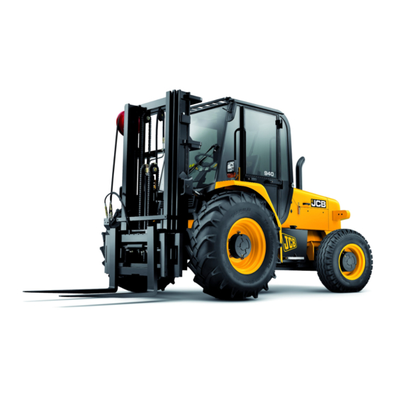
OPERATOR MANUAL
THIS MANUAL SHOULD ALWAYS STAY WITH THE MACHINE
RTFL - 926, 930, 940, 950
ENGLISH - 9811/5700 - ISSUE 7 - OCTOBER 2013
Copyright © 2004 JCB SERVICE.
All rights reserved. No part of this publication may be reproduced, stored in a retrieval system, or transmitted in any form or
by any other means, electronic, mechanical, photocopying or otherwise, without prior permission from JCB SERVICE.
A4-7-SkidSteer - Printed In England

Advertisement

Table of Contents
loading
Need help?

Need help?

Do you have a question about the RTFL 926 and is the answer not in the manual?

Questions and answers

Summary of Contents for jcb RTFL 926

  • Page 1 All rights reserved. No part of this publication may be reproduced, stored in a retrieval system, or transmitted in any form or by any other means, electronic, mechanical, photocopying or otherwise, without prior permission from JCB SERVICE. A4-7-SkidSteer - Printed In England...
  • Page 2 Notes: 9811/5700...
  • Page 3: Table Of Contents

    Left Side, Right Side ................. 1 Cab/Canopy ..................... 1 Cross References ..................1 Machine Description ..................2 The JCB Rough Terrain Fork Lift .............. 2 Intended Use .................... 2 Component Locations ................2 Safety Check List ................... 5 Safety - Yours and Others ................ 5 General Safety ..................
  • Page 4 Contents Contents Page No. Operating Levers ..................44 Introduction ..................... 44 Mast Controls ..................45 Auxiliary Controls ................... 46 Sideshift Carriage (if fitted) ..............47 Safety Equipment ..................48 Control Locks ..................48 Beacon ....................49 Fire Extinguisher (If fitted) ..............50 Before Starting the Engine ................
  • Page 5 Contents Contents Page No. Routine Maintenance Service Requirements ................. 87 Introduction ..................... 87 Owner/Operator Support ................ 87 Service/Maintenance Agreements ............87 Initial Service and Inspection ..............87 Fit for Purpose Tests for Lifting Equipment ..........88 Obtaining Replacement Parts ..............88 Health and Safety ..................
  • Page 6 Contents Contents Page No. Electrical System ..................126 Battery ....................126 Jump Starting the Engine ..............128 Fuses ....................130 Link Box Fuses ..................131 Relays ....................132 Engine ....................... 134 Oil and Filter ..................134 Cooling System ..................136 Front End Accessory Drive Belt ............
  • Page 7 Contents Contents Page No. Tyre Sizes and Pressures ................180 Introduction ................... 180 Specifications ..................181 Warranty Information Machine Service Record Sheet ..............183 Registration Information ................185 European Community Standards EC Declaration of Conformity ..............187 Introduction ................... 187 Explanation of the EC Declaration of Conformity .........
  • Page 8 Contents Contents Page No.
  • Page 9: Safety Notices

    Operator Manual. If you do not other operators. understand anything, ask your employer or JCB dealer to explain it. In this publication and on the machine, there are safety INT-1-4-2 notices.
  • Page 10 Safety Notices Important Information Page left intentionally blank viii 9811/5700-7 viii...
  • Page 11: Introduction

    Cab/Canopy T1-003_2 If there is anything you are not sure about, ask your JCB This manual frequently makes references to the cab. For distributor or employer. Do not guess, you or others could instance, 'do not operate the machine without a manual in be killed or seriously injured.
  • Page 12: Machine Description

    Introduction Machine Description Machine Description The JCB Rough Terrain Fork Lift Component Locations K Fig 2. ( T This is a self-propelled, seated-operator, rough terrain – Items 1 to 7: counterbalance truck for operation on unimproved natural K Fig 3. ( T –...
  • Page 13 Introduction Machine Description Fig 2. 9811/5700-7...
  • Page 14 Introduction Machine Description T047530-4 Fig 3. Engine Compartment 9811/5700-7...
  • Page 15: Safety Check List

    JCB distributor to explain them. with it. If you don't, you will not do your job well, and you will be a danger to yourself and others.
  • Page 16 Sparks in altered in any way which could affect or invalidate any such an area could cause an explosion or fire of these requirements. For advice consult your JCB resulting in death or serious injury. Distributor.
  • Page 17: Operating Safety

    Introduction Safety Check List Operating Safety WARNING Work Sites WARNING Work sites can be hazardous. Inspect the site before working on it. You could be killed or injured if the Machine Condition ground gives way under your machine or if piled A defective machine can injure you or others.
  • Page 18 5-5-1-1_2 INT-2-1-1 WARNING WARNING Use only the JCB approved attachments that are specified for your machine. Operating with non- Airborne particles of light combustible material such specified attachments can overload the machine, as straw, grass, wood shavings, etc. must not be...
  • Page 19 Introduction Safety Check List DANGER CAUTION Working Platform Fork Spacing Using the machine as a working platform is Loads can fall off incorrectly spaced forks. Always hazardous; you can fall off and be killed or injured. space the forks correctly for the load. Make sure the Never use the machine as a working platform.
  • Page 20 Introduction Safety Check List DANGER WARNING Forks/Working Platform Visibility Using the forks alone as a working platform is Accidents can be caused by working in poor visibility. hazardous; you can fall off and be killed or injured. Use your lights to improve visibility. Keep the road Never use the forks as a working platform.
  • Page 21: Maintenance Safety

    Introduction Safety Check List MaIntenance Safety WARNING Should the machine start to roll over, you can be WARNING crushed if you try to leave the cab. If the machine starts to roll over, do not try and jump from the cab. Communications Stay in the cab, with your seat belt fastened.
  • Page 22 Introduction Safety Check List WARNING CAUTION Fluid Under Pressure It is illegal to pollute drains, sewers or the ground. Fine jets of fluid at high pressure can penetrate the Clean up all spilt fluids and/or lubricants. skin. Keep face and hands well clear of fluid under pressure and wear protective glasses and gloves.
  • Page 23 CAUTION WARNING 'O' rings, Seals and Gaskets Certain seals and gaskets (e.g. crankshaft oil seal) on Badly fitted, damaged or rotted 'O' rings, seals and JCB machines contain fluoroelastomeric materials gaskets can cause leakages and possible accidents. ® ® such...
  • Page 24 Prior to any work being carried out on using a brush to clean components. systems incorporating accumulators, the system pressure must be exhausted by a JCB distributor, as HYD-1-3_3 the sudden release of the hydraulic fluid or gas may cause injury.
  • Page 25 Introduction Safety Check List DANGER WARNING Electrolyte Wheels and tyres are heavy. Take care when lifting or Battery electrolyte is toxic and corrosive. Do not moving them. breathe the gases given off by the battery. Keep the electrolyte away from your clothes, skin, mouth and Store with care to ensure that they cannot fall and eyes.
  • Page 26: Safety Labels

    Keep all safety labels clean and readable. Replace lost or damaged safety labels. Make sure replacement parts include safety labels where necessary. Each safety label has a part number printed on it, use this number to order a new safety label from your JCB distributor. 9811/5700-7...
  • Page 27: Safety Label Identification

    Introduction Safety Labels Safety Label Identification ISO-011C ISO-04A ISO-06B ISO-05C ISO-15C ISO-05B ISO-01A ISO-10A Fig 4. Safety Label Locations 9811/5700-7...
  • Page 28 Introduction Safety Labels Part Numbers and Descriptions ISO-011C Part Number: 817/70011 ISO-01A Description: Fall from raised Part Number: 817/70014 attachment. Do not stand/ride on the bucket or forks. Description: Warning. Read operator manual before you operate the machine. 817/70011 817-70011-2 817-70014-3 ISO-15C Part Number: 332/P4712...
  • Page 29: Identifying Your Machine

    Introduction Identifying Your Machine Identifying Your Machine Machine Identification Plate Typical Product Identification Number (PIN) - Early Machines Your machine has an identification plate mounted as shown. The serial numbers of the machine and its major 01234567 units are stamped on the plate. Note: The machine model and build specification is World Manufacturer Identification (3 Digits) indicated by the PIN.
  • Page 30 Introduction Identifying Your Machine Typical Product Identification Number (PIN) - Later Machines 01234567 World Manufacturer Identification (3 Digits) Machine Model (3 Digits) 926, 930, 940 or 950 Wheel Drive Option (2 Digits) 02 = 2 Wheel Drive 04 = 4 Wheel Drive Check letter (1 Digit) The Check Letter is used to verify the authenticity of the machine’s PIN.
  • Page 31: Component Identification Plates

    A typical engine identification number is explained as follows: 320/40001 00001 Engine Type S = 4.4 litre series. JCB Dieselmax (Tier 2) C007820-C2 Fig 6. Engine A = Naturally aspirated B = Turbocharged C = Turbocharged and intercooled JCB Dieselmax (Tier 3)
  • Page 32 Introduction Identifying Your Machine Transmission Identification Numbers Gearbox The gearbox has a serial number stamped on a data plate Axles K Fig 9. ( T Y as shown. 22). The front axle serial number is stamped on a data plate mounted to the front of the left hand axle arm.
  • Page 33: Rops/Fops Certification Plate

    A screen guard can also be fitted to provide protection from objects FOPS Data Plate coming from the front, contact your JCB distributor. WARNING Do not use the machine if the falling objects protection level provided by the structure is not sufficient for the application.
  • Page 34: Machine Security

    JCB is doing everything possible logged onto the CESAR or DVLA databases, and a change to help combat this. of keeper form. Your JCB Distributor or Dealer will be pleased to provide information on any of these sensible precautions. ACT NOW! JCB Plantguard JCB PLANTGUARD is a comprehensive package available to help you safeguard your machine.
  • Page 35: Introduction

    Do not guess. If there is anything you do not understand, ask your JCB distributor. The operator must always be aware of events happening in or around the machine. Safety must always be the most important factor when you operate the machine.
  • Page 36: Before Entering The Cab

    Operation Before Entering the Cab Before Entering the Cab T2-025_4 The following checks should be made each time you return d Inspect the windows for cracks and damage. to the machine after leaving it for any period of time. We Glass splinters can blind.
  • Page 37: Entering And Leaving The Cab

    Operation Entering and Leaving the Cab Entering and Leaving the Cab WARNING Entering/Leaving Entering or leaving the cab or canopy must only be made where steps and handrails are provided. Always face the machine when entering and leaving. Make sure the step(s), handrails and your boot soles are clean and dry.
  • Page 38: Doors And Windows

    Operation Doors and Windows Doors and Windows Opening and Closing the Doors To open a door from the outside, unlock it with the key provided and press the lock barrel. Close the door from the inside by pulling it firmly; it will latch itself.
  • Page 39: Seat Controls

    Operation Seat Controls Seat Controls Introduction Weight T2-007_3 Sit in the seat and check the position of indicator 4. It WARNING should be level with the front edge of the side frame as shown in 4A. Seat Position the seat so that you can comfortably reach If the indicator is behind the frame as shown in 4B, the machine controls.
  • Page 40: Basic Seat (Type 2)

    Operation Seat Controls Basic Seat (Type 2) Suspension Seat (Option) To adjust the seat, move lever A in the direction shown and Fore/Aft - Move lever 1 horizontally and slide the seat to slide the seat forward or back. Release the lever and make the position you want.
  • Page 41: Seat Belt

    Operation Seat Belt Seat Belt Inertia Reel Seat Belt the belt too sharply or if the machine is parked on an incline. In such cases, ease the belt gently from its reel T2-001_2 holder. WARNING Check the Seat Belt is Operating Correctly If you do not wear your seat belt you could be thrown about inside the machine, or thrown out of the Sit correctly in the seat and fasten the seat belt as...
  • Page 42: Cab Layout

    Operation Cab Layout Cab Layout Note: The cab layout illustration is of a typical machine, for variations see the relevant page in this manual. S715280-5 Fig 19. 9811/5700-7...
  • Page 43: Component Key

    Operation Cab Layout Component Key K Steering Wheel ( T 34). K Gear Lever ( T 35). K Starter Switch ( T 39). K Park Brake Lever ( T 34). K Accelerator Pedal ( T 34). K Foot Brake Pedal ( T 34).
  • Page 44: Drive Controls, Switches And Instruments

    Operation Drive Controls, Switches and Instruments Drive Controls, Switches and Instruments Drive Controls Transmission Lever Steering Wheel WARNING T2-048 You and others can be killed or injured if you operate Turn the steering wheel in the direction you want to go. the forward/reverse lever while you travel.
  • Page 45 Operation Drive Controls, Switches and Instruments Gear Lever To select a gear, move the lever as shown on the shift pattern. When the machine is stationary, make sure the forward/reverse selector is at neutral (N) and the engine at idle before selecting a gear. The machine can be moved off in any gear depending on ground conditions.
  • Page 46: Switches

    Operation Drive Controls, Switches and Instruments Switches Side Console Console Switches Side Lights and Headlights Three position rocker switch with Introduction backlight. The switch functions operate SW-001_2 when the starter switch is in the ON and The installed switches and their positions can change OFF positions.
  • Page 47 Operation Drive Controls, Switches and Instruments Beacon Air-Conditioning (if fitted) Two position rocker switch. The switch Two position rocker switch. The switch functions operate when the starter switch functions operate when the starter switch is in the ON and OFF positions. is in the ON position.
  • Page 48 Operation Drive Controls, Switches and Instruments Multi-Purpose Steering Column Switch Note: The steering column switch on your machine may not include all of the following functions. Direction indicators (Right) Pull the lever towards you to indicate a right turn. Switch the indicators off when you have completed the turn.
  • Page 49 Operation Drive Controls, Switches and Instruments Starter Switch Rear Window Wiper This is a rotary switch A, operated by the starter key. It has Rocker switch A. Press down to switch on rear window four positions. The key can be removed only with the wiper.
  • Page 50 Operation Drive Controls, Switches and Instruments Auxiliary Power Socket The socket X supplies a 12 Volt DC power supply to electrical accessories (from the battery). Only connect items which are compatible with the power rating of the socket (Refer to Electrical System, Fuses) and have the correct plug.
  • Page 51: Instrument Panel

    Operation Drive Controls, Switches and Instruments Instrument Panel Instruments The instruments and indicator lights are grouped together Fuel Gauge K Fig 29. ( T on an instrument panel. 41). Indicates the level of diesel fuel in the tank. Do not let the tank run dry, or air will enter the fuel system.
  • Page 52 Operation Drive Controls, Switches and Instruments Warning Lights light will illuminate indicating that the manifold heater is ON. When the light extinguish the engine is ready to start. Water in Fuel Indicator Audible/Visual. Lights up when there is water in the fuel system.
  • Page 53: Air Conditioning And Heater Controls

    Operation Drive Controls, Switches and Instruments K Starting the Engine ( T Air Conditioning and Heater Controls Start the engine. 53). Note: Before starting the engine make sure the air Heater Controls conditioning is switched off (knob A, position 0). Hot air is directed to the windscreen by a pipe in the front Turn knob A clockwise to position 1 to turn the air of the cab.
  • Page 54: Operating Levers

    Operation Operating Levers Operating Levers Introduction WARNING Control lever/switch action may vary on machines, WARNING instructional labels near the levers/switches show by symbols, which levers/switches cause what actions. Controls Before operating control levers/switches check the You or others can be killed or seriously injured if you instructional label to make sure you select the desired operate the control levers from outside the machine.
  • Page 55: Mast Controls

    Operation Operating Levers Mast Controls Tilt Mast Forward/Tilt Mast Back To tilt the mast forward C, push the lever forward. To tilt the Raise Mast / Lower Mast mast back D, pull the lever back. To raise the mast A (and carriage), pull the lever back. To lower the mast B (and carriage), push the lever forward.
  • Page 56: Auxiliary Controls

    Operation Operating Levers Auxiliary Controls The machine can be fitted with a single or twin auxiliary circuit. These can be used to operate optional attachments when connected to the quick release couplings J mounted K Optional front machine. Attachments ( T 163).
  • Page 57: Sideshift Carriage (If Fitted)

    Operation Operating Levers Sideshift Carriage (if fitted) If the machine is fitted with a sideshift carriage it can be operated by lever 3. To move the carriage to the left E, push the lever forward. To move the carriage to the right F, pull the lever back.
  • Page 58: Safety Equipment

    Operation Safety Equipment Safety Equipment Control Locks The requirement for control lever lock/isolation varies according to local legislation. You must comply with local legislation at all times. The locks are designed to lock or isolate the controls in the neutral position. Lock the controls before you travel on public roads.
  • Page 59: Beacon

    Operation Safety Equipment Beacon In certain territories you will be breaking the law if you do not fit a rotating beacon before you travel on public highways - make sure you are complying with local laws. Note: Be careful when you operate the machine with a beacon.
  • Page 60: Fire Extinguisher (If Fitted)

    Operation Safety Equipment Fire Extinguisher (If fitted) Location The fire extinguisher is found under the seat and is held in position by a stowage bracket. Keep the fire extinguisher in this position until you need to use it. Operation T2-041_3 WARNING Do not use the fire extinguisher in a confined space.
  • Page 61: Before Starting The Engine

    Inspect the ROPS/FOPS structure for damage. CAUTION Get your JCB Distributor to repair any damage. On machines fitted with hose burst protection valves Make sure all its securing bolts are fitted and the attachments cannot be lowered with the engine correctly tightened.
  • Page 62 Operation Before Starting the Engine Adjust the seat so that you can comfortably reach all the driving controls. You should be able to apply full brake pedal travel with your back against the seat back. If fitted, adjust the armrest so that you can reach and operate the controls without stretching.
  • Page 63: Starting The Engine

    Operation Starting the Engine Starting the Engine Note: Control and switch locations are provided within this iii When the warning light goes OFF, turn the K Cab Layout ( T publication. 32). starter switch to the 'start' position III and hold it there until the engine starts.
  • Page 64: Preparing The Machine For Travel

    Important: Whilst this information is believed to be requirements of these regulations; they are not necessarily correct, JCB cannot be aware of all circumstances in which the applied law. the JCB machine may be operated on a Public Highway...
  • Page 65: Site Travel Position

    Operation Preparing the Machine for Travel Site Travel Position The recommendations given below ARE NOT necessarily the applied law, please make sure you are complying with the relevant local laws. Centralise the carriage. Tilt the mast fully back. Lower the carriage so that the heels of the forks (if fitted) are 100 mm-150 mm (4 in-6 in) above the ground.
  • Page 66: Getting The Machine Moving

    Operation Getting the Machine Moving Getting the Machine Moving Operating Practices If the load will be pushing the machine on a downslope, select first gear (1) before starting downhill. P5-2020_2 WARNING Use the brake pedal to prevent overspeeding down a slope.
  • Page 67: Operating Procedure

    Operation Getting the Machine Moving Operating Procedure Push the brake pedal hard down. c Lift the forward/reverse lever from its detent After you have warmed up the engine and tested the park position and select forward or reverse. brake, move off as described below. Note: When forward or reverse drive is selected, an Note: Control and switch locations are provided within this audible alarm will sound and a warning light will show to...
  • Page 68: Stopping And Parking The Machine

    Operation Stopping and Parking the Machine Stopping and Parking the Machine Note: Control and switch locations are provided within this DANGER K Cab Layout ( T publication. 32). Before lowering the attachments to the ground, make Stop the machine on dry and level ground where the sure that the machine and the area around it are clear machine will not be a hazard or danger.
  • Page 69 Operation Stopping and Parking the Machine WARNING Entering/Leaving Entering or leaving the cab or canopy must only be made where steps and handrails are provided. Always face the machine when entering and leaving. Make sure the step(s), handrails and your boot soles are clean and dry.
  • Page 70: Working With The Machine

    Attention is also drawn to the various safety aspects of The information in this section is given in good faith and in operating on site. light of the best information available, JCB can accept no responsibility recommendations, advice,...
  • Page 71 Operation Working with the Machine WARNING WARNING Reworking Old Sites Underground Gas Pipes There could be dangerous materials such as Before you start using the machine, check with your asbestos, poisonous chemicals or other harmful local gas company if there are any buried gas pipes on substances buried on the site.
  • Page 72: Working With The Mast

    Operation Working with the Machine Working with the Mast CAUTION Know the weight of the load before trying to lift it. Introduction Raise the load only a few inches at first, to check that the machine is stable. Lower the load straight away if DANGER the machine begins to feel unstable.
  • Page 73 If you are unsure of the suitability of the machine for a sick or tired operator is a dangerous operator. specific task, contact your JCB distributor who will be – Is supervision needed? Is the supervisor adequately pleased to advise you.
  • Page 74 Operation Working with the Machine The load Lifting and Loading Operations P5-2067 – How heavy is it? Is it within the capabilities of the Ensure that all local and national legislation governing machine? operations such as lifting and loading are fully satisfied before operating the machine.
  • Page 75 Forks can break resulting in a loss of load and possible injury. 0003 JCB approved forks for this machine are marked with a maximum load capacity rating A. The rating shows the maximum load capacity in kilograms (kg) that the forks can carry safely at the maximum load centre B of 500mm (20 inches).
  • Page 76 Operation Working with the Machine Repositioning the Forks WARNING If the fork/locking pin is not fully engaged, the fork WARNING could become unintentionally disengeged. Forks are heavy. Take care when spacing forks or 12-6-1-13 folding back the forks. Remove the lifting equipment and make sure the 0002 forks are correctly located.
  • Page 77 Operation Working with the Machine Handling Palleted Loads Loading Space the forks as wide as possible to suit the load. WARNING K Repositioning the Forks ( T 66). Make sure you know the weight of the load before lifting it. Do not exceed the SWL of the machine with the carriage/attachment you are using.
  • Page 78 Operation Working with the Machine Check that it is clear behind you, then slowly reverse Unloading on the Ground the machine away in first gear. CAUTION Stop the machine. Engage the park brake. Put the transmission in neutral. Put the mast and carriage Unloading into the travel position.
  • Page 79 Operation Working with the Machine Unloading Above Ground Level Unload above ground level only after you fully understand how to handle palleted loads. The basic procedure is the same, but remember the following points: K Stacking Loads ( T 72). Approach the unload area on centre, with the rear wheels straight.
  • Page 80 Operation Working with the Machine Handling Bales Handling Drums Handle bales only after you fully understand how to handle Handle drums only after you fully understand how to palleted loads. The basic procedure is the same, but handle palleted loads. The basic procedure is the same, remember the following points: but remember the following points: Lower the forks and tilt them forward as shown.
  • Page 81 Operation Working with the Machine Note: The clamp arms will open when contact is made with Handling Irregular Loads the drums and close when the drums seat securely in the clamp Handle irregular loads only after you fully understand how to handle palleted loads.
  • Page 82 Operation Working with the Machine Stacking Loads T2-070 Box Pallets Stack box pallets straight and square. For extra stability, stagger the top row. 151990-3 Fig 55. Cylindrical Loads Stack cylindrical loads tightly together and level. Wedge both ends of each row. If building a pyramid stack, wedge both ends of the bottom row.
  • Page 83: Use Of Machines On Gradients Or Slopes

    Operation Working with the Machine Use of Machines on Gradients or Slopes WARNING Ensure that you have been trained and are familiar with the use of machines on gradients, and understand the adverse affects that gradients and site conditions can have on stability. Never use the machine on a gradient if you do not understand the recommended practices for the use of machines in such applications.
  • Page 84 Operation Working with the Machine Lifting Operations on Gradients WARNING Conducting lifting operations on gradients can be dangerous. The machine can become laterally unstable and tip over if the instructions in this section are not followed and understood. You and others can be seriously injured or killed.
  • Page 85: Operating Environment

    Install a cold weather starting aid. In very low temperatures, -18°C (0°F) and below, additional starting aids may be needed. Examples are fuel, oil and coolant heaters. Ask your JCB distributor for advice. Important: Do not connect two batteries in series to give 24 volts for starting as this can cause damage to the electrical circuits.
  • Page 86: Refuelling A Machine

    At the end of every working day, fill the tank with the correct type of fuel. This will prevent overnight condensation from Consult your fuel supplier or JCB distributor about the developing in the fuel. suitability of any fuel you are unsure of.
  • Page 87 Operation Refuelling a Machine Fig 60. 9811/5700-7...
  • Page 88: Moving A Disabled Machine

    The procedure for doing this will depend on the machine's condition and its hydraulic circuits. For this reason you should contact your JCB Distributor for help and advice before attempting this work. Attach the drawbar to a suitable location.
  • Page 89: Transporting The Machine

    Operation Transporting the Machine Transporting the Machine Loading a Machine on to a transporter 800990-3 Fig 62. a Make sure the ramps are correctly in place and WARNING secure. The safe transit of the load is the responsibility of the b Set the carriage central.
  • Page 90 Operation Transporting the Machine 298261-2 Fig 63. 9811/5700-7...
  • Page 91 Operation Transporting the Machine Putting the Mast into the Transport Position With the machine safely in position on the trailer, the park brake engaged and the transmission in neutral, do the following: Unfasten both tilt cylinder restraint wires from the mast.
  • Page 92: Unloading A Machine From The Transporting Vehicle

    Operation Transporting the Machine Unloading a Machine from the Remove the securing straps from the machine and stow them. Transporting Vehicle Start the machine, tilt the mast back and raise the Position the transporting vehicle on firm level ground. forks. Raise the carriage far enough so that the forks do not foul on the ramps when you drive off.
  • Page 93 Operation Transporting the Machine Taking the Mast Out of the Transport Position The mast must be returned to the normal position before driving the RTFL off the transporter. WARNING Mast Tilt The machine is equiped with special laydown tilt cylinders. The FULL tilt feature is to be used for TRANSPORTING on trucks or trailer only and not on the work site.
  • Page 94: Lifting A Machine

    Remove the rear fenders (if fitted, contact your local everybody. Work sites can be noisy, do not rely on JCB dealer) and all loose equipment from the spoken commands. machine exterior.
  • Page 95: Storage Of The Machine

    (in case the machine does not is in storage. start at the end of the storage period). Note: JCB Dealers must check stock monthly. Place suitable timbers under the machine to eliminate direct contact with the ground.
  • Page 96: Take The Machine Out Of Storage

    Operation Storage of the Machine Operate the hydraulic controls. Make sure that the hydraulic functions operate correctly. Prepare the machine for storage. Refer to Put the Machine into Storage. Take the Machine Out of Storage T2-079 Examine the coolant condition. Replace If necessary Examine all fluid levels.
  • Page 97: Routine Maintenance

    JCB together with your Distributor wants you to be maximum performance, economy and ease of use under a completely satisfied with your new JCB machine. If you do wide variety of operating conditions. Prior to delivery, your encounter a problem however, you should contact your...
  • Page 98: Fit For Purpose Tests For Lifting Equipment

    A Parts Book for your machine is available from your JCB Distributor. The Parts Book will help you identify parts and order them from your JCB distributor.
  • Page 99: Health And Safety

    Hygiene vomiting, seek medical advice. Used engine oil contains harmful contaminants which can cause skin JCB lubricants are not a health risk when used properly for cancer. Do not handle used engine oil more than their intended purposes. necessary. Always use barrier cream or wear gloves to prevent skin contact.
  • Page 100 Routine Maintenance Health and Safety Avoid skin contact with oil soaked clothing. Don't keep oily rags in pockets. Wash dirty clothing before re-use. Throw away oil-soaked shoes. First Aid - Oil Eyes In the case of eye contact, flush with water for 15 minutes. If irritation persists, get medical attention.
  • Page 101: Battery

    Routine Maintenance Health and Safety Battery CAUTION T3-061 Damaged or spent batteries and any residue from fires WARNING or spillage should be put in a closed acid proof receptacle and must be disposed of in accordance Batteries give off an explosive gas. Do not smoke with local environmental waste regulations.
  • Page 102 Routine Maintenance Health and Safety Warning Symbols First Aid - Electrolyte The following warning symbols may be found on the Do the following if electrolyte: battery. Gets into your eyes Symbol Meaning Immediately flush with water for 15 minutes, always get Keep away from children.
  • Page 103: Service Schedules

    Routine Maintenance Service Schedules Service Schedules Introduction How to Use the Service Schedules T3-036_3 T3-012_4 In the example shown, A shows all service requirements to WARNING be carried out every 10 hours and B shows the requirements to be carried out every 500 hours. Maintenance must be done only by suitably qualified and competent persons.
  • Page 104: Pre-Start Cold Checks, Service Points And Fluid Levels

    Routine Maintenance Service Schedules Pre-start Cold Checks, Service Points and Fluid Levels Operation 1000 2000 6000 ENGINE      Coolant Quality and Level - Check   Cooling System - Drain and Refill   Oil level - Check ...
  • Page 105 Routine Maintenance Service Schedules Operation 1000 2000 6000        Tyre Pressures/Condition - Check        - Check Tightness of Wheel Nuts        Rear Hub Bearings (2WD) - Grease ...
  • Page 106 For Fit and Security - Check (1) First 100 Hours Service only, to be completed by your JCB Distributor. (2) If operating under arduous conditions, change the engine oil and filter every 250 hours. (3) The oil service interval will be affected if there is a high sulphur content in the fuel. Refer to Fuel System for more information.
  • Page 107: Functional Test And Final Inspection

    Routine Maintenance Service Schedules Functional Test and Final Inspection Operation 1000 2000 6000 ENGINE      - Check and Adjust Idle Speed      - Check Torque Converter Stall Speed     ...
  • Page 108 Fit for Purpose Test - Complete (1) First 100 Hours Service only, to be completed by your JCB Distributor. (2) Jobs which should only be done by a specialist. (3) Fully raise and lower the mast daily to lubricate the cylinder bores and cylinder rods.
  • Page 109: Fluids, Lubricants And Capacities

    Fluids, Lubricants and Capacities JCB recommend that you use the JCB lubricants shown as they have been verified by JCB for use on JCB machines. However, you could use other lubricants that are equivalent to the JCB standards and quality or offer the same machine component protection.
  • Page 110: Coolant Mixtures

    The correct concentration of antifreeze protects the engine against frost damage in winter and provides year round protection against corrosion. The protection provided by JCB High Performance Antifreeze and Inhibitor is shown below. 50% Concentration (Standard) Protects against damage down to -40 °C (-39 °F) 60% Concentration (Extreme Conditions Only) Protects against damage down to -56 °C (-68 °F)
  • Page 111: Fuels

    Routine Maintenance Fluids, Lubricants and Capacities Fuels CAUTION Consult your fuel supplier or JCB distributor about the Acceptable and Unacceptable Fuels suitability of any fuel you are unsure of. T3-031 GEN-9-2 Important: No warranty liability whatsoever will be accepted for failure of fuel injection equipment where the failure is attributed to the quality and grade of the fuel used.
  • Page 112 Note: If performance related issues are to be reported to – Lubrizol 539N. Dosage (on Swedish low sulphur fuel) JCB Service, and the engine has been run on biodiesel, 250 ppm. then the fuel system must be filled with standard diesel (at –...
  • Page 113 Routine Maintenance Fluids, Lubricants and Capacities Sulphur Content Effects of Fuel Contaminates T3-032 T3-033 High sulphur content can cause engine wear. (High The effect of dirt, water and other contaminants in diesel sulphur fuel is not normally found in North America, can be disastrous for injection equipment: Europe or Australia.) If you have to use high sulphur fuel you must change the engine oil more frequently.
  • Page 114: Prepare The Machine For Maintenance

    Routine Maintenance Prepare the Machine for Maintenance Prepare the Machine for Maintenance Introduction WARNING Maintenance must be done only by suitably qualified and competent persons. Before doing any maintenance make sure the machine is safe, it should be correctly parked on level ground. To prevent anyone starting the engine, remove the starter key.
  • Page 115: How To Make The Machine Safe (Mast Lowered)

    Routine Maintenance Prepare the Machine for Maintenance How to Make the Machine Safe (Mast How to Make the Machine Safe (Mast Lowered) Lifted) Important: You can complete most of the maintenance WARNING procedures with the mast lowered. Unless a maintenance procedure instructs you differently, you must lower the Mast Support Chains mast.
  • Page 116 Routine Maintenance Prepare the Machine for Maintenance Vent the hydraulic system. Refer to Hydraulic System, Releasing the Hydraulic Pressure. Check the support chain(s) for total safety. Fig 70. Typical Duplex Mast Fig 71. Typical Triplex Mast 9811/5700-7...
  • Page 117 Routine Maintenance Prepare the Machine for Maintenance Removing the Mast Support Chains Raise the mast/carriage to take the weight off the chains. Switch OFF the engine and remove the starter key. Remove the chain(s). Fig 72. Typical Freelift Mast 9811/5700-7...
  • Page 118: Cleaning The Machine

    Routine Maintenance Cleaning the Machine Cleaning the Machine Introduction CAUTION T3-062_3 The engine or certain components could be damaged Clean the machine using water and or steam. Do not allow high pressure washing systems; special mud, debris etc. to build upon the machine. precautions must be taken if the engine is to be washed using a high pressure system.
  • Page 119: Cleaning The Machine

    Routine Maintenance Cleaning the Machine Cleaning the Machine WARNING To avoid burning wear personal protective equipment (PPE) when handling hot components. To protect your eyes, wear personal protective equipment (PPE) when using a brush to clean components. HYD-1-3_3 WARNING Airborne particles of light combustible material such as straw, grass, wood shavings, etc.
  • Page 120 Routine Maintenance Cleaning the Machine Fig 74. c Do not wash any part of the: Fuel injection pump. ii Cold start device. iii Electrical shut off solenoid (ESOS). iv Electrical connections. d Ensure that the alternator, starter motor and any other electrical components are shielded and not directly cleaned by high pressure cleaning system.
  • Page 121: Checking For Damage

    Routine Maintenance Checking for Damage Checking for Damage Check the Machine Body and Structure Install the valve caps firmly to prevent dirt from entering the valve. Inspect for leaks when you check the tyre T3-063_5 pressures. Make sure that all guards and protective devices are in place, attached by their locking devices and free from Inspect the tyre valve for leaks, when you check the tyre damage.
  • Page 122: Check The Electrical Circuits

    Modifications and repairs that are For assistance, contact your JCB distributor. Failure to not approved by the manufacturer may be dangerous take these precautions could result in death or injury to the and will invalidate the ROPS/FOPS certification.
  • Page 123: Greasing

    Routine Maintenance Greasing Greasing Introduction Preparing the Machine for Greasing T3-028_2 You must grease the machine regularly to keep it working Make the machine safe before you start a greasing efficiently. Regular greasing will also lengthen the procedure. Refer Prepare Machine machine's working life.
  • Page 124: Daily

    Routine Maintenance Greasing Daily Rear Axle Pivot Pin 2 Grease Points. Fig 76. 9811/5700-7...
  • Page 125 Routine Maintenance Greasing Rear Axle 14 grease points. Fig 77. 9811/5700-7...
  • Page 126 Routine Maintenance Greasing Rear Driveshafts (4 Wheel Drive Machines) 3 grease points. Fig 78. Front Driveshaft 3 grease points. Fig 79. 9811/5700-7...
  • Page 127 Routine Maintenance Greasing Mast Tilt Rams and Pivots 6 grease points. Fig 80. 9811/5700-7...
  • Page 128: 250 Hours

    Routine Maintenance Greasing 250 Hours Mast Chains Fig 81. Remove old oil and apply JCB Chain Lubricant. Make sure the chains are slack before applying lubricant. 9811/5700-7...
  • Page 129: Oiling

    Routine Maintenance Oiling Oiling The following points should be lightly oiled with engine oil. Control Levers Oil the clevis A of each hydraulic control lever. Remove the WARNING gaiter retaining plate B and lift the lever gaiter C to gain Make the machine safe before working underneath it.
  • Page 130: Cylinder Bores And Rods

    Routine Maintenance Oiling Cylinder Bores and Rods Fully raise and lower the mast daily to lubricate the cylinder bores and cylinder rods. Fig 84. 9811/5700-7...
  • Page 131: Access Panels

    Routine Maintenance Access Panels Access Panels Introduction T3-100 When placed in their maintenance position, the access panels give you access to parts or areas of the machine that are not required during machine operation. Before you operate the machine, make sure that all of the access panels are in their operation position and secure.
  • Page 132: Engine Side Panels

    Routine Maintenance Access Panels Engine Side Panels The machine is fitted with engine side panels A, located either side of the engine. The panels can be removed to provide better access for maintenance tasks. Fig 86. To remove a panel: K Access Panels ( T Open the engine cover.
  • Page 133: Brakes

    Fully apply park brake. If you have any queries concerning the park brake test or adjustment procedures, consult your local JCB distributor. Start the engine and raise the attachments to the appropriate travel position.
  • Page 134 Test the park brake. If the brake fails the test, repeat steps 1, 2 and 3. If there is no more adjustment and pin B is at the end of its travel get the brake checked by your JCB dealer. Fig 87. 9811/5700-7...
  • Page 135: Foot Brake

    WARNING Faulty brakes can kill. If you have to top up the brake reservoir frequently, get the brake system checked by your JCB Dealer. Do not use the machine until the fault has been put right. 2-3-2-5_1 The brake master cylinder reservoir is in the engine compartment.
  • Page 136: Electrical System

    Routine Maintenance Electrical System Electrical System Battery If the machine has a battery isolator, move the switch to the ON position. Battery Disconnection/Connection Close and lock the access panels. T3-019_4 WARNING Checking the Electrolyte Level T3-020_3 Keep metal watch straps and any metal fasteners on Low maintenance batteries used in normal temperate your clothes, clear of the positive (+) battery terminal.
  • Page 137 Routine Maintenance Electrical System Close and lock the access panels. Battery Isolator (if fitted) To disconnect the battery from the machine electrics a battery isolator has been fitted. CAUTION Before carrying out arc welding on the machine, disconnect the battery and alternator to protect the circuits and components.
  • Page 138: Jump Starting The Engine

    If you do not know the voltage of your booster (slave) supply, then contact your JCB dealer for advice. Do not attempt to jump-start the engine until you are sure of the voltage of the booster (slave) supply.
  • Page 139 Routine Maintenance Electrical System The park brake should have been engaged when the machine was last parked. If it is not engaged, engage it now. The engine will not start unless the park brake is on. Set all switches in the cab to off. Connect the booster cables as follows: a Open the engine cover.
  • Page 140: Fuses

    Routine Maintenance Electrical System Fuses All Models Circuit Rating CAUTION Transmission Fuses Instrument illumination Always replace fuses with ones of correct ampere rating to avoid electrical system damage. Brake lights 8-3-3-5 Engine Shut-off Solenoid (ESOS) The electrical circuits are protected by fuses. The fuses are Front wash/wipe located in a fuse box inside the door.
  • Page 141: Link Box Fuses

    Routine Maintenance Electrical System Link Box Fuses To further protect the machine wiring harnesses and electrical circuits, a fuse link box A is fitted as shown. Remember to check the main circuit fuses as well as the link box fuses shown on this page. Note: An additional optional fuse may be fitted for cold start.
  • Page 142: Relays

    Routine Maintenance Electrical System Relays Buzzer Flashers All Models Park brake lamp The relays are located behind the side console J. They are Ignition separated into the banks. Neutral start Transmission dump To access the relays, unscrew the five fasteners K and remove the panel.
  • Page 143 Routine Maintenance Electrical System Air Conditioning (if fitted) Machines with air conditioning are fitted with two additional relays A. The relays are located in the engine compartment, next to the battery. Fig 97. 9811/5700-7...
  • Page 144: Engine

    Routine Maintenance Engine Engine Oil and Filter Checking the Oil Level Get access to the engine. Refer to Access Panels, Engine Cover. Check that the oil level is between the maximum and minimum marks on the dipstick A. WARNING Do not exceed the correct level of engine oil in the sump.
  • Page 145 Routine Maintenance Engine Changing the Oil and Filter Loosen and remove the filter housing drain plug E and its 'O' ring J. Let the oil fully drain, then clean and T3-030_2 refit the drain plug with a new 'O' ring. Torque the Drain the oil when the engine is warm as contaminants drain plug to 40-60Nm (30-44lbf ft).
  • Page 146: Cooling System

    Routine Maintenance Engine Cooling System Checking the Coolant Level Visually check the coolant level daily. Note: Do not depend on the coolant level indicator to illuminate before adding coolant. Check the quality of the antifreeze mixture every year - before the cold weather starts. Change it every two years. WARNING The cooling system is pressurised when the coolant is hot.
  • Page 147 Routine Maintenance Engine Changing the Coolant WARNING The cooling system is pressurised when the coolant is hot. When you remove the cap, hot coolant can spray out and burn you. Make sure that the engine is cool before you work on the cooling system. 9-3-3-1_2 Get access to the engine.
  • Page 148: Front End Accessory Drive Belt

    Routine Maintenance Engine Front End Accessory Drive Belt Inspecting the Drive Belt T3-029 At the recommended service interval, visually inspect the Introduction belt for damage. The front end accessory drive belt (FEAD) drives the Get access to the drive belt. Refer to Front End alternator, water pump...
  • Page 149 Routine Maintenance Engine Changing the Drive Belt Get access to the drive belt. Refer to Front End Accessory Drive Belt, Introduction. Use a 16mm (5/8 in.) socket located on the hexagon spigot nut D, carefully rotate the tensioner against the spring force in direction E.
  • Page 150: Air Filter

    Routine Maintenance Engine Air Filter Cleaning the Air Filter Dust Valve Important: Do not run the engine with the dust valve K Cleaning the Pre-Cleaner (if fitted) removed. T3-015-2 Important: Do not run the engine with the filter pre-cleaner Check the dust valve K is not blocked. removed.
  • Page 151 Routine Maintenance Engine Get access to the engine. Refer to Access Panels, Carefully insert the new inner element D into the Engine Cover. canister. Make sure it seats correctly by smearing seal F with grease and checking for a witness mark K Cleaning the Pre- Clean the Pre-Cleaner (if fitted).
  • Page 152: Fuel System

    Routine Maintenance Fuel System Fuel System Introduction Water Separator and Engine Fuel Filter Introduction WARNING Fuel To get access to the water separator A and engine fuel Fuel is flammable; keep naked flames away from the filter B for maintenance: fuel system.
  • Page 153 Routine Maintenance Fuel System Draining the Water Separator and Engine Fuel Filter If there is water in the fuel or if the cab warning light illuminates, drain the water separator and engine filter as detailed. Get access to the Water Separator and Engine Fuel Filter.
  • Page 154 Routine Maintenance Fuel System Changing the Water Separator Pre Filter Get access to the Water Separator and Engine Fuel Filter. Refer to Water Separator and Engine Fuel Filter, Introduction. Drain and remove the water separator bowl C. K Draining the Water Separator and Engine Fuel Filter ( T 143).
  • Page 155 Routine Maintenance Fuel System Changing the Engine Fuel Filter Element Get access to the Water Separator and Engine Fuel Filter. Refer to Water Separator and Engine Fuel Filter, Introduction. Thoroughly clean the outside of the filter housing and around the filter head. Loosen the drain tap B and allow the fuel to drain into a suitable container.
  • Page 156: Bleeding The Fuel System

    If the engine continues to run roughly, check again for air in the fuel system. If the fault persists contact your nearest JCB dealer. Fig 112. Fig 111. 9811/5700-7...
  • Page 157: Hydraulic System

    Routine Maintenance Hydraulic System Hydraulic System Introduction CAUTION Do not allow dirt to enter the system. Before WARNING disconnecting any part of the system, thoroughly clean around the connection. When a component has The temperature of the hydraulic oil will be high soon been disconnected, always fit protective caps and after stopping the engine.
  • Page 158: Releasing The Hydraulic Pressure

    Routine Maintenance Hydraulic System Releasing the Hydraulic Pressure Important: This procedure is only to be used before disconnecting the hydraulic hoses. Before removing any other hydraulic component refer to the relevant removal procedure. Make the machine safe with the mast lowered. Refer to Prepare the Machine for Maintenance.
  • Page 159: Oil And Filter

    CAUTION If the fluid is cloudy, then water or air has Fig 113. contaminated the system. This could damage the hydraulic pump. Contact your JCB Distributor immediately. 12-5-1-4 Look at the fluid level in the sight glass A. The level should be at the red mark (or above), but not over the sight glass.
  • Page 160 Routine Maintenance Hydraulic System Changing the Filter Element WARNING Fluid Under Pressure Fine jets of fluid at high pressure can penetrate the skin. Keep face and hands well clear of fluid under pressure and wear protective glasses and gloves. Hold a piece of cardboard close to suspected leaks and then inspect the cardboard for signs of fluid.
  • Page 161: Transmission

    Routine Maintenance Transmission Transmission Gearbox Checking the Transmission Oil Level Make the machine safe with the mast lowered. Refer to Prepare the Machine for Maintenance. Start and run the engine slowly for a period not exceeding five minutes. This allows the oil to fill filter, pump, torque converter, oil cooler and hoses.
  • Page 162 Clean the strainer with a suitable solvent. Follow the solvent manufacturer's instructions on safety. Fit the strainer E and a new gasket F. Apply JCB Threadlocker and Sealer to bolts D before fitting and tightening them. Torque tighten the bolts to 10 Nm (7 lbf ft).
  • Page 163: Axles

    Routine Maintenance Transmission Axles Checking the Axle Oil Level CAUTION The oil level must be checked with the machine level, otherwise a false indication of the amount of oil will be given. 16-3-5-3_2 Make the machine safe with the mast lowered. Refer to Prepare the Machine for Maintenance.
  • Page 164 Routine Maintenance Transmission Changing the Axle Oil Make the machine safe with the mast lowered. Refer to Prepare the Machine for Maintenance. Place a container of suitable size beneath plug B to catch the oil. Remove the drain plug B and its seal. Allow oil to drain out.
  • Page 165 Place a container of suitable size beneath plug will reduce as a result of brake wear. 122-C to catch the oil. Consult your JCB Distributor for advice if necessary. CAUTION Checking the Hub Oil Levels Oil will gush from the hole when the drain plug is T3-011_2 removed.
  • Page 166: Tyres And Wheels

    Routine Maintenance Tyres and Wheels Tyres and Wheels Tyre Inflation in a qualified tyre mechanic. The tyre mechanic should use a tyre inflation cage and the correct equipment to do the job. Introduction T3-066 Prepare the wheel. WARNING Before you add air to the tyre, make sure it is correctly An exploding tyre can kill.
  • Page 167: Changing A Wheel

    Routine Maintenance Tyres and Wheels Changing a Wheel WARNING Deflate the tyre you wish to change before removing the wheel from the machine. Air pressure in the tyres can cause the tyre and rim sections to explode causing serious injury or death. Never loosen the nuts that hold the inner and outer wheel halves together when there is air pressure in the tyre.
  • Page 168 Routine Maintenance Tyres and Wheels 732160-V2 Fig 125. Checking the Wheel Nut Torques T3-014_3 WARNING If, for whatever reason, a wheel stud is renewed, all the studs for that wheel must be changed as a set, since the remaining studs may have been damaged. 2-3-2-8 On new machines, and whenever a wheel has been removed, check the wheel nut torques every two hours...
  • Page 169: Forks

    Note: The locking clamp X is only required when the WARNING individual fork width is less than 125mm (5in). Contact your JCB dealer to procure and install a locking clamp if Do not try to correct the alignment of the fork tips by required.
  • Page 170 Routine Maintenance Forks Installation Note: Make sure that you install the correct type of fork for the type of carriage fitted. Do not attempt to fit the incorrect forks. Park the machine on solid level ground. Make sure the park brake is engaged and select neutral. Position the fork so that the upper hook D can engage K Fig 126.
  • Page 171: Windscreen Washer

    Routine Maintenance Windscreen Washer Windscreen Washer Checking the Level Fill the windscreen washer bottle A with a suitable liquid. The liquid should contain a de-icing fluid to prevent freezing. Do not use engine coolant antifreeze. Fig 128. 9811/5700-7...
  • Page 172: Fire Extinguisher (If Fitted)

    Routine Maintenance Fire Extinguisher (if fitted) Fire Extinguisher (if fitted) T3-022 Checking the Fire Extinguisher Check the fire extinguisher for damage, security and signs of leaking. Check that the gauge A indicates that the extinguisher is charged i.e. the needle is in the GREEN segment. Note: If the needle is in or very near the RED segment at either end of the gauge, the extinguisher must be serviced or replaced.
  • Page 173: Optional Attachments

    JCB cannot be held responsible. In addition the The use of non-approved attachments could invalidate machine's warranty and any other legislative compliance your warranty. may be affected by the use of non JCB approved 2-4-5-2_1 attachments. CAUTION If your machine needs the hydraulic system adapting to...
  • Page 174: Attachments For Your Machine

    Optional Attachments Attachments For Your Machine Attachments For Your Machine Attachments will help increase the productivity of your machine, for more information contact your JCB Distributor. Remember, do not operate attachments until you have read and fully understand the attachment operating instructions.
  • Page 175: Connecting/Disconnecting Hydraulic Hoses

    Optional Attachments Connecting/Disconnecting Hydraulic Hoses Connecting/Disconnecting Hydraulic Hoses T4-004_2 Introduction Connecting the Hydraulic Hoses Make machine safe. Refer Routine WARNING Maintenance, Prepare Machine Maintenance. Fluid Under Pressure Fine jets of fluid at high pressure can penetrate the Vent the hydraulic system. Refer to Routine skin.
  • Page 176: Disconnecting The Hydraulic Hoses

    Optional Attachments Connecting/Disconnecting Hydraulic Hoses Disconnecting the Hydraulic Hoses Make machine safe. Refer Routine Maintenance, Prepare Machine Maintenance. Vent the hydraulic system. Refer to Routine Maintenance, Releasing the Hydraulic Pressure. T037420 Fig 131. Disconnect the hoses. To allow for length changes when the hose is If the hoses have quick releases couplings, then refer pressurised, do not clamp at the bend.
  • Page 177: Quick Release Couplings

    Optional Attachments Connecting/Disconnecting Hydraulic Hoses Quick Release Couplings by dirt in the coupling or physical damage due to abuse. – Connect and disconnect new couplings two or three WARNING times to work the PTFE seals. Sometimes a new coupling will stick if the seal has not been worked. The external surfaces of the couplings must be clean before connecting or disconnecting.
  • Page 178 Optional Attachments Connecting/Disconnecting Hydraulic Hoses Connecting Quick Release Couplings Remove any residual hydraulic pressure trapped in the service line hose. Wipe the two faces of the male and female couplings and make sure they are clean. Make sure that ball C in the female coupling is located in one of its slots.
  • Page 179: Work Platforms

    In the case of uncertainty, guidance should be sought from the relevant local or government authority. JCB supply integrated work platforms solely for use in Europe which comply with the requirements of European Directive 2006/42/EC. Contact your dealer for further details.
  • Page 180 Optional Attachments Work Platforms Page left intentionally blank 9811/5700-7...
  • Page 181: Specifications

    Specifications Static Dimensions All Models Note: Dimensions relative to standard fork size 1067 x 100 x 50mm (42 x 4 x 2in) and tyres. Fig 134. Table 7. mm (ft-in) mm (ft-in) mm (ft-in) mm (ft-in) A Overall cab height 2570 (8-5) 2570 (8-5) 2570 (8-5)
  • Page 182 Specifications Static Dimensions mm (ft-in) mm (ft-in) mm (ft-in) mm (ft-in) Mast Closed Height 3.6 m mast 2950 (9-8) 2950 (9-8) 2850 (9-4) 4.5 m mast 2410 (7-10) 2410 (7-10) 2540 (8-4) 5.5 m mast 2950 (9-8) 2950 (9-8) 2850 (9-4) 3320 (10-8) 6.55 m mast 3320 (10-11)
  • Page 183: Performance Dimensions

    Specifications Performance Dimensions Performance Dimensions Lift Performance Important: The following data is intended for quick reference only. Always refer to the rating plate in the cab. Refer to Fork Ratings, Working with the Machine, Operation. Note: Complies with ISO 22915-13. Fig 135.
  • Page 184 Specifications Performance Dimensions Important: The following data is intended for quick reference only. Always refer to the rating plate in the cab. Refer to Fork Ratings, Working with the Machine, Note: Complies with ISO 22915-13. Operation. Fig 136. Lift Performance 3.6m (11ft 10in) Duplex mast 4.5m (14ft 9in) Free lift mast 5.5m (18ft 0in) Triplex mast...
  • Page 185 Specifications Performance Dimensions Important: The following data is intended for quick reference only. Always refer to the rating plate in the cab. Refer to Fork Ratings, Working with the Machine, Note: Complies with ISO 22915-13. Operation. Fig 137. Lift Performance 3.6m (11ft 10in) Duplex mast 4.5m (14ft 9in) Free lift Triplex mast 5.5m (18ft 0in) Triplex mast...
  • Page 186: Maximum Wading Depth

    Specifications Performance Dimensions Important: The following data is intended for quick reference only. Always refer to the rating plate in the cab. Refer to Fork Ratings, Working with the Machine, Note: Complies with ISO 22915-13. Operation. 3.0t 4.5t 823680-2 Fig 138. Lift Performance 6.7m (21ft 6in) Triplex Bar and Industrial carriage Maximum Wading Depth...
  • Page 187: Noise Data

    The noise data values shown only apply to CE marked (1) Nett Installed power (kW) to ISO14396 machines. For information relating to this machine when used with other JCB approved attachments, please refer to the literature accompanying the attachments. Definition of terms: A-weighted sound pressure level measured at the operator's station.
  • Page 188: Vibration Data

    Specifications Vibration Data Vibration Data Introduction Minimising Exposure to Vibration T5-001 Exposure to vibration can be minimised through: To assist in compliance with European Directive 2002/44/ EC, duty specific vibration emission values for this – Selection of the correct size and capacity of machine, machine type have been provided on the following page(s) equipment attachments...
  • Page 189: All Models

    Specifications Vibration Data All Models Table 10. Whole-Body Vibration Emission Under Representative Operating Conditions (According to the Intended Use) Dominant Axis (X, Y or Z) Machine Operating Duties Whole-body vibration emission determined in accordance Machine Operating Duties with ISO 2631-1:1997 for this machine type is 0.38 m/s normalised to an 8-hour reference period [A(8)] and based Low Idle upon a test cycle "defined in SAE J1166".
  • Page 190: Tyre Sizes And Pressures

    European Tyre and Rim Technical Organisation (ETRTO) standards to satisfy machine stability performance. If the tyres fitted to your machine are not listed, then contact your JCB Distributor for advice, do not guess tyre pressures. 9811/5700-7...
  • Page 191: Specifications

    Specifications Tyre Sizes and Pressures Specifications All Models Table 11. Model 926-2 Item Size Ply Make Name Pressure lbf/in Size Offset 16.5/85 X 24 8 SOLIDEAL SLR1 14 x 24 ET + 20 15.5 X 25 GOODYEAR SURE GRIP LOADER (SGL) 43.5 12 x 25 ET - 20...
  • Page 192 Specifications Tyre Sizes and Pressures Table 14. Model 930-4 Item Size Make Name Pressure Size Offset lbf/in 16.5/85 X 24 8 SOLIDEAL SLR1 14 x 24 ET + 20 15.5 X 25 GOODYEAR SURE GRIP LOADER (SGL) 56.5 12 x 25 ET - 20 15.5/80 X 24 12 GOODYEAR SURE GRIP IMPLEMENT (SGI) 3.0...
  • Page 193: Warranty Information

    Warranty Information Machine Service Record Sheet Warranty Information Machine Service Record Sheet T6-003 Installation Checklist 3000 Hrs./36 Month Annual insurance Date: Date: Hour reading: 1st 100 Hrs./1 Month 3500 Hrs./42 Month Date: Date: Hour reading: Hour reading: 500 Hrs./6 Month 4000 Hrs./48 Month Annual insurance Date:...
  • Page 194 Warranty Information Machine Service Record Sheet 6500 Hrs./78 Month 9500 Hrs./114 Month Date: Date: Hour reading: Hour reading: 7000 Hrs./84 Month 10000 Hrs./120 Month Annual insurance Annual insurance Date: Date: Hour reading: Hour reading: 7500 Hrs./90 Month Date: Hour reading: 8000 Hrs./96 Month Annual insurance Date:...
  • Page 195: Registration Information

    Installing Engineer Installing Engineer Customer's Name Dealer Copy (U.K. and Eire only) - Do not send back to JCB Service. A copy of the registration details to be Address sent direct to: The Equipment Register Ltd. (T.E.R.) Bath and West Buildings P.D.I.
  • Page 196 Warranty Information Registration Information Page left intentionally blank 9811/5700-7...
  • Page 197: European Community Standards

    European Community Standards EC Declaration of Conformity Introduction TS-006_3 A completed copy of the EC Declaration of Conformity is supplied with all machines manufactured according to EC type examination and/or self-certification requirements. A sample copy of the EC Declaration of Conformity and a summary of the information that can appear is provided.
  • Page 198 European Community Standards EC Declaration of Conformity 9814-0850-4-GB Fig 140. 9811-5700-7...
  • Page 199: Explanation Of The Ec Declaration Of Conformity

    Explanation of the EC Declaration of Annex VI - Procedure 1 Conformity A. V. Technology K Fig 140. ( T 188). A.V. House Birdhall Lane JCB Compact Products Ltd. Stockport Harewood Estate Cheshire Leek Road United Kingdom Cheadle SK3 0XU...
  • Page 200 European Community Standards EC Declaration of Conformity Page left intentionally blank 9811-5700-7...

This manual is also suitable for:

Rtfl 930Rtfl 940Rtfl 950

Table of Contents

Save PDF