Table of Contents
Advertisement
Available languages
Available languages
Quick Links
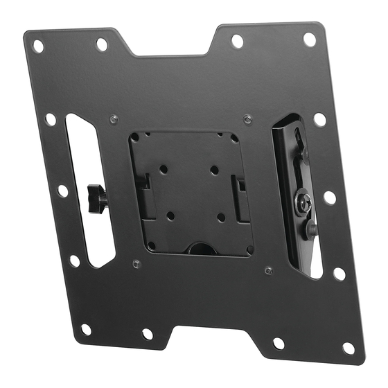
Installation and Assembly:
SmartMount™ Universal Tilt Wall Mount
for 10" - 37" (25 - 94 cm) LCD Flat Panel Screens
Models: ST632P, ST632P-S, ST632, ST632-S, RTFPT 632, RTFPT 632-S,
SWV220/BK, SWV220/SI
Features:
• Fits 10" - 37" (25 - 94 cm) flat panel screens
• One-touch tilt for effortless positioning and adjustment of the screen
• Integrated security features provide effective theft deterrence
U L
C
US
©
Max Load Capacity: 115 lb (52.2 kg)
ISSUED: 02-05-09 SHEET #: 202-9321-1
Advertisement
Chapters
Table of Contents

Related Manuals for PEERLESS Mounts SmartMount ST632P


Summary of Contents for PEERLESS Mounts SmartMount ST632P
- Page 1 Installation and Assembly: SmartMount™ Universal Tilt Wall Mount for 10" - 37" (25 - 94 cm) LCD Flat Panel Screens Models: ST632P, ST632P-S, ST632, ST632-S, RTFPT 632, RTFPT 632-S, SWV220/BK, SWV220/SI Features: • Fits 10" - 37" (25 - 94 cm) flat panel screens •...
-
Page 2: Table Of Contents
NOTE: Read entire instruction sheet before you start installation and assembly. WARNING • Do not begin to install your Peerless product until you have read and understood the instructions and warnings contained in this Installation Sheet. If you have any questions regarding any of the instructions or warnings, for US customers please call Peerless customer care at 1-800-865-2112, for all international customers, please contact your local distributor. -
Page 3: Parts List
Before you begin, make sure all parts shown are included with your product. SWV220/BK SWV220/SI Parts List ST632P-S, ST632P, RTFPT632 RTFPT632-S ST632 ST632-S Part # Part # Description Qty Part # Part # A hook bracket 095-1346 095-4346 095-1346 095-4346 B tilt assembly 095-0359 095-0360... -
Page 4: Installation To Single Wood Stud Wall
Installation to Single Wood Stud Wall WARNING • Installer must verify that the supporting surface will safely support the combined load of the equipment and all attached hardware and components. • Tighten wood screws so that wall plate is firmly attached, but do not overtighten. Overtightening can damage the screws, greatly reducing their holding power. -
Page 5: Installation To Solid Concrete Or Cinder Block
Installation to Solid Concrete or Cinder Block WARNING • When installing Peerless wall mounts on cinder block, verify that you have a minimum of 1-3/8" (35 mm) of actual concrete thickness in the hole to be used for the concrete anchors. Do not drill into mortar joints! Be sure to mount in a solid part of the block, generally 1"... -
Page 6: Attaching Adapter Plate To Screen With Vesa 200 Or 200 X 200 Mounting Pattern
Attaching Adapter Plate to Screen with VESA 200 or 200 x 200 Mounting Pattern Note: For VESA 75 mm and 100 mm patterns, see following page. Attach hook bracket (A) to adapter plate (C) using four M5 x 6 mm screws (J) and #10 washers (K) as shown. -
Page 7: Attaching Hook Bracket To Screen With Vesa 75 Or 100 Mounting Pattern
Attaching Hook Bracket to Screen with VESA 75 or 100 Mounting Pattern WARNING • If screws don't get three complete turns in the screen inserts or if screws bottom out and bracket is still not tightly secured, damage may occur to screen or product may fail. FOR VESA ®... -
Page 8: Installing And Removing Flat Panel Screen
Installing and Removing Flat Panel Screen Attach screen to tilt assembly (B). Tighten M5 x 6 mm SCREEN screw (J or N) to lock screen to tilt assemby. J or N For security installation tighten M5 x 6 mm socket pin screw (N) using 4 mm security driver (O) to lock screen to tilt assemby. - Page 9 Anbringung und Zusammenbau: SmartMount™-Universal-Wandkipphalter für LCD-Flachbild- schirme von 10 - 37 Zoll (25 - 94 cm) Modelle: ST632P, ST632P-S, ST632, ST632-S, RTFPT 632, RTFPT 632-S, SWV220/BK, SWV220/SI Merkmale: • Für Flachbildschirme von 10-37 Zoll (25 - 94 cm) • Mühelose Positionierung und Einstellung des Bildschirms durch einmaliges Antippen ©...
- Page 10 HINWEIS: Lesen Sie die gesamte Anleitung, bevor Sie mit der Anbringung und dem Zusammenbau beginnen. ACHTUNG • Beginnen Sie mit der Anbringung Ihres Peerless-Produkts erst, nachdem Sie die in dieser Montageanleitung enthaltenen Anleitungen und Achtungshinweise gelesen und sich gründlich mit ihnen vertraut gemacht haben. Falls Sie Fragen hinsichtlich irgendeiner der Anleitungen oder Achtungshinweise haben, wenden Sie sich in den USA bitte an den Peerless-Kundendienst unter der Rufnummer 1-800-865-2112.
-
Page 11: Teileliste
Vergewissern Sie sich vor Beginn der Arbeiten, dass alle dargestellten Teile mit Ihrem Produkt mitgeliefert wurden. SWV220/BK SWV220/SI Teileliste ST632P, ST632P-S, RTFPT632 RTFPT632-S ST632 ST632-S Teile Nr. Teile Nr. Beschreibung Anz. Teile Nr. Teile Nr. A Hakenhalterung 095-1346 095-4346 095-1346 095-4346 B Kippeinheit 095-0359... -
Page 12: Anbringung An Wand Mit Einer Holzständerreihe
Anbringung an Wand mit einer Holzständerreihe ACHTUNG • Bei der Anbringung muss darauf geachtet werden, dass die Wand die kombinierte Last von Bildschirm und allen Befestigungsteilen und -komponenten tragen kann. • Ziehen Sie die Schrauben fest genug an, dass die Wandplatte sicher befestigt ist, doch ohne sie zu überdrehen. Durch Überdrehen können die Schrauben beschädigt werden, wodurch ihr Haltevermögen stark reduziert wird. -
Page 13: Anbringung An Massivbeton Oder Porenbetonstein
Anbringung an Massivbeton oder Porenbetonstein ACHTUNG • Bei der Anbringung von Peerless-Wandhaltern an Porenbetonstein muss sichergestellt werden, dass die tatsächliche Stärke des Betons, in den das Loch für die Betondübel gebohrt wird, mindestens 35 mm (1 3/8 Zoll) beträgt. Bohren Sie nicht in Mörtelfugen! Achten Sie darauf, dass die Anbringung an einem massiven Teil des Blocks erfolgt, im Allgemeinen mindestens 25 mm (1 Zoll) von der Blockseite entfernt. -
Page 14: Befestigung Von Adapterplatte An Bildschirm Unter Verwendung Von Vesa-Montagemuster 200 Oder 200 X 200
Befestigung von Adapterplatte an Bildschirm unter Verwendung von VESA- Montagemuster 200 oder 200 x 200 HINWEIS: Die VESA-Muster 75 mm und 100 mm sind auf der folgenden Seite aufgeführt. Bringen Sie die Hakenhalterung (A) mit vier M5 x 6 mm Schrau- ben (J) und Scheiben Nr. -
Page 15: Befestigung Der Hakenhalterung Am Bildschirm Unter Verwendung Von Vesa-Montagemuster 75 Oder 100
Befestigung der Hakenhalterung am Bildschirm unter Verwendung von VESA- Montagemuster 75 oder 100 ACHTUNG • Sind die Schrauben nicht um drei volle Umdrehungen in die Löcher des Bildschirms eingeschraubt oder stoßen sie unten an und die Halterung ist noch immer nicht sicher befestigt, kann der Bildschirm beschädigt werden oder das Produkt kann versagen. BEI MONTAGEMUSTER VESA®... -
Page 16: Anbringung Und Abnahme Des Flachbildschirms
Anbringung und Abnahme des Flachbildschirms Bringen Sie den Bildschirm an der Kippeinheit (B) an. Ziehen Sie die M5 x 6 mm Schraube (J oder N) fest, um den Bildschirm an der BILDSCHIRM Kippeinheit zu befestigen. Ziehen Sie die M5 x 6 mm Schraube (N) mit Hilfe des 4 mm Sicherheitstreibers (O) fest, um den Bildschirm unter Anwendung der Sicherheitsfunktion an der Kippeinheit zu J or N...
Need help?
Do you have a question about the SmartMount ST632P and is the answer not in the manual?
Questions and answers