
Related Manuals for CAME BPT LVKIT


Summary of Contents for CAME BPT LVKIT
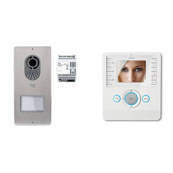
- Page 1 VIDEO KIT FB01045-EN OPALE PEV/01 VAS/101 LVC/01 LVKIT EN English INSTALLATION MANUAL...
-
Page 2: General Notes
General Notes • Read the instructions carefully before beginning the installation and carry out the actions as specifi ed by the manufacturer. • The installation, programming, commissioning and maintenance of the product must only be carried out by qualifi ed technicians, properly trained in compliance with the regulations in force, including health and safety measures and the disposal of packaging. -
Page 3: Technical Data
Once the connections have been made, hook the video terminal to the metal support . To release the unit from the metal support, press the plastic hook and lift the terminal Technical data Type Maximum current draw (mA) Current draw in stand-by mode (mA) <... - Page 4 Setting melodies ☞ All the programming stages described below must be carried out in sequence: 1- Going into Programming. Press button 5 times in 5 secs beep beep A short beep confi rms that you have entered programming mode. 2- Programming the melody associated with a call from the entry panel.
-
Page 5: Wall-Mounted Installation
OPALE Wall-mounted installation Separate the unit body from the frame Fasten the OPALEKP wall-mounting support (optional) to the recessed box using the screws provided; the support is compatible with the following recessed box models: round 60 mm Ø, 503 rectangular, 506E rectangular, and OPALESI (optional). - Page 6 Recessed installation on plasterboard wall Hold the box up against the plasterboard wall and mark the 4 reference points for installation 1. Make 4 holes, 10 mm in diameter, at the reference points. Cut the plaster- board to make a compartment for the box in the wall B. Remove the 2 tabs on the box as shown in the fi gure C.
-
Page 7: Terminal Board
Terminal board Local power supply – 16-18 VDC BUS line input 16-18VDC Doorbell – Alarm input Closing resistance (CL.RES) The jumper should be inserted in the last device in the line only. Master/Slave selector (SKM) If two or more receivers have been confi gured to answer the same call, the preview image of the caller is shown only on the master device(s). -
Page 8: Technical Features
VAS/101 Installation The power supplier must ALWAYS be installed horizontally. The device can be installed on a DIN rail (EN 50022) A in an appropriate electric panel B. For the overall dimensions see fi gure C. NOTE. Proper ventilation is required if the power supplier 43,5 is installed in a metal container. -
Page 9: Wall Mounting
LVC-01 Wall mounting A. With the wall plugs Using the Allen screwdriver remove the cover provided fi x the entry panel at the desired height B respecting the positioning of the lens of the surveillance camera B, take off the terminal board cover C and Push through pipe make the connections. - Page 10 Recessed installation Wall in the recessed box at the desired height, respecting the positioning of the lens of the surveillance camera . Push the pipe with the system conductors through one of the breaking points ( point A). When using the recessed box any possible deformations can be avoided by using the spacer provided ( point B).
- Page 11 Technical data Type LVC/01 Power supply (VDC) 16-18 Absorption (mA) Consumption in stand-by mode (mA) Storage temperature (°C) -25 ÷ + 70 °C Operating temperature (°C) -15 ÷ +50 IP Degree Size of name cards (mm) 53x13x0,3 or 53x33x0,3 Standard video PAL/NTSC Resolution (pixel) 680x512...
-
Page 12: Exiting Programming
Programming for the fi rst time Entering programming mode PROG Press the PROG key for at least 3 seconds 1 and then release it (within 6 seconds), as soon as the PROG >3’’ >3’’ LED lights up and the key back lighting fl ashes as illustrated in fi gure 2. <6’’... - Page 13 Reprogramming Going into Programming PROG Press the PROG key for at least 3 seconds 1 and then release it (within 6 seconds) as soon as the PROG >3’’ >3’’ LED fl ashes and the key back lighting lights up as illustrated in fi gure 2. <6’’...
- Page 14 Programming an intercommunicating group Programming an intercommunicating group must be carried out AFTER assigning the call key to all of the receivers. Assigning intercommunicating groups PROG With the SW3 jumper inserted, press the PROG key for at least 8 seconds and release it (within 11 >8’’...
- Page 16 CAME S.p.A. Via Martiri Della Libertà, 15 31030 Dosson di Casier - Treviso - Italy tel. (+39) 0422 4940 - fax. (+39) 0422 4941...