Table of Contents
Advertisement
Quick Links
FMS-1655L Room Pressure Controller
Installation Manual
LB-FMS1655L-S01
LB-FMS1655L-S02
LB-FMS1655L-T01
LB-FMS1655L-T02
Application
These installation instructions guide the installer through the installation of the FMS-1655 Room Pressure Controller.
Please read these instructions thoroughly before beginning installation.
North American Emissions Compliance
United States
This equipment has been tested and found to comply with the limits for a Class A digital device pursuant to Part
15 of the FCC Rules. These limits are designed to provide reasonable protection against harmful interference
when this equipment is operated in a commercial environment. This equipment generates, uses, and can radiate
radio frequency energy and, if not installed and used in accordance with the instruction manual, may cause
harmful interference to radio communications. Operation of this equipment in a residential area may cause harmful
interference, in which case users will be required to correct the interference at their own expense.
Canada
This Class (A) digital apparatus meets all the requirements of the Canadian Interference-Causing Equipment
Regulations.
Cet appareil numérique de la Classe (A) respecte toutes les exigences du Règlement sur le matériel brouilleur du
Canada.
Installation
NOTICE
Risk of Property Damage.
Ensure that the power source conforms to the requirements of the equipment. Failure to use a correct power
source may result in permanent damage to the equipment.
NOTICE
Risque de dégâts matériels.
S'assurer que la source d'alimentation électrique est conforme aux spécifications de l'équipement. L'utilisation
d'une source d'alimentation électrique inappropriée risque d'endommager irrémédiablement l'équipement.
IMPORTANT:
The FMS-1655 Room Pressure Controller must be wired to 24 VAC only. Wiring the unit to 110
VAC will cause serious damange and void the warranty.
Use of the software that is in (or constitutes) this product or access to the cloud or hosted services applicable to this product,
if any, is subject to applicable terms set forth at www.johnsoncontrols.com/techterms. Your use of this product constitutes an
agreement to such terms. If you do not agree to be bound by such terms, you may return the unused product to your place of
purchase.
(LonWorks
only products)
®
Code No. LIT-12013118, Rev. A
Central Monitoring Station
The Next Generation in Critical Airflow Controls
Issued August 2018
JCI CMS-1655
JCI FMS-1655
Advertisement
Table of Contents

Related Manuals for Johnson Controls FMS-1655L


Summary of Contents for Johnson Controls FMS-1655L
- Page 1 FMS-1655L Room Pressure Controller (LonWorks only products) ® Installation Manual LB-FMS1655L-S01 Code No. LIT-12013118, Rev. A LB-FMS1655L-S02 LB-FMS1655L-T01 Issued August 2018 LB-FMS1655L-T02 Application These installation instructions guide the installer through the installation of the FMS-1655 Room Pressure Controller. Please read these instructions thoroughly before beginning installation.
- Page 2 CONTROLLER SETTINGS This form should be completed during the initial configuration for each room pressure controller. Room Name / Number Unit Model Number and Serial Number (ESN) Analog Input Normal Operating Pressure (reading with door closed) Positive Isolation Setpoint Negative Isolation Setpoint Neutral Isolation Setpoint Pressure Deadband Analog Output...
- Page 3 Delay Time Base (secs or mins) Delay Setting (0 – 60) Engineering Units Inches of Water or Pascals BRAND LB = Johnson Controls UNIT FMS = Flow Monitor Station (FMS) SERIES 1655 = BACnet / N2 Controller 1655L = LonWorks Controller...
- Page 4 WARNING Warning Failure to follow the wiring diagrams could result in damage to your equipment and could void your warranty. Under no circumstances should a single transformer be split between actuator and controller. Doing so will damage the actuator, the transformer, the controller or all units. A single 120/24V 30Va transformer is required for the controller and a separate 120/24V 20Va transformer is required for the actuator.
-
Page 5: Table Of Contents
Specifications……………………………………………………………………………………………………………………………..6 Overview………………………………………………………………………………………………………………………………..7 MOUNTING/WIRING FMS-1655L Surface Mount Case Dimensions……………………..………………………………………………………………… 8 FMS-1655L Flush Mount Display Dimensions…………………...…………………………………………………………………… 9 FMS-1655L Surface Mount Display Dimensions………………………………………………..……………………………..10 - 11 Remote Sensor Installation………………………………………………………..………..………………………………..12 - 14 Remote Sensor Connector Strip…………………………………………………………………………………………………………15 Function Descriptions……………………………………………………………………………………………………………………...16 Analog Output to Modulated Air Controller ……………………………………………………………………………………………17 Analog Input to Remote Pressure Sensor - 4-20mA Out……………………………………………………………………………18... -
Page 6: General
Color Depth...…………………………………………………………………………………………………………………………………18-bit or 262K colors Backlight Color..………………………………………………………………………………………………………………………………………………White Luminous Intensity..………………………………………………………………………………………………………………………………min 2500 cd/m2 Mechanical FMS-1655L Display Module Housing (Surface Mount)……………………………………………………………………………………3”W x 5”H x 1.13”D FMS-1655L Display Module Housing (Flush Mount)…………………………………………………………………………………5.6”W x 8.5”H x 0.75”D FMS-1655L Controller Housing…………………………………………………………………………………………………………4.6”W x 6.6”H x 1.9”D Environmental Operating Temperature………………………………………………………………………………………………………………..32°... -
Page 7: Overview
The FMS-1655L provides built-in diagnostic The FMS-1655L has enhanced graphics and functions of the FMS-1655L, except for Relay tools for troubleshooting during installation, Saftey Halo™ edge lighting that provides a full 2, which is reserved for the display power including manual override capabilities and 180°... -
Page 8: Fms-1655L Surface Mount Case Dimensions
FMS-1655L Surface Mount Case Dimensions 3" 3 / 4 " ® Left Angle Side View Control Unit Cable provided terminated at control unit 5" Right Side View Adapter 1.13” 3 / 4 " (Inside Control Unit) -
Page 9: Fms-1655L Flush Mount Display Dimensions
MOUNTING/WIRING FMS-1655L Flush Mount Display Dimensions The FMS-1655L Flush Mount display is mounted flushed to the wall using the supplied retro fit ring or wall box. Use the retro fit ring as a template to mark the wall for cutout. -
Page 10: Fms-1655L Surface Mount Display Dimensions
5.05” ø 0.143” The FMS-1655L display backplate may be mounted directly to a standard single-gang wall box using the two slots along the centerline. Use the backplate as a template to mark the mounting holes and the cable access hole at the center of the backplate. - Page 11 MOUNTING/WIRING Controller Mounting Hole Patterns...
-
Page 12: Remote Sensor Installation
10. Install the louvered cover plate. 1. Cut an opening in the wall of the isolation room for the single-gang low voltage 11. At the FMS-1655L controller, connect the bracket and remote sensor electronics. three leads from the remote sensor to Nominal hole dimensions are 3.65”... - Page 13 ISOLATION short as possible to prevent kinks. ROOM Terminal For connection of transmitter to FMS-1655L Orange wall bracket to be installed first Thin Silicone Caulking by using the rotating (apply around tube and between...
- Page 14 Terminal For connection of transmitter to FMS-1655L To FMS Thin Silicone Caulking Controller (apply around tube and Rotating clamps secure between stainless steel...
-
Page 15: Remote Sensor Connector Strip
Mounting / Wiring Remote Sensor Connector Strip The electrical connections to the FMS-1655L are made via a convenient removable terminal block as shown below. All wiring should conform to the local regulations and National Electrical Code. LED2 LED2 Take care not to run sensor wiring in the same conduit as... -
Page 16: Function Descriptions
Unit has 4 analog inputs which can be configured for 4-20 mA, 0-5VDC, or 0-10VDC. Power The FMS-1655L can be powered by either 24 VAC or 24 VDC. A 120 VAC to 24 VAC Step Down Isolation Transformer is provided and recommended. This power must be from a Class 2 supply only. -
Page 17: Analog Output To Modulated Air Controller
Mounting / Wiring Remote Sensor Analog Output to Modulated Air Controller CONNECTIONS FOR POWERED OUTPUT LED2 LED2 Purchased Separately Aout NT_1 Vsel NT_2 SHLD Power Supply Optional External Transmitter NT_1 AI_4 DI_4 NT_2 4-20mA Loop AI_3 SHLD DI_3 DI_2 AI_2 AI_1 EXT. -
Page 18: Analog Input To Remote Pressure Sensor - 4-20Ma Out
Mounting / Wiring Analog Input to Remote Pressure Sensor - 4-20mA Out LED2 LED2 Aout NT_1 Vsel NT_2 SHLD NT_1 AI_4 DI_4 NT_2 AI_3 SHLD DI_3 4-20mA OUT DI_2 AI_2 AI_1 Remote EXT. SNSR Pressure +Vin RLY4 DI_1 Sensor C3/4 AO_4 RLY3 AO_3... -
Page 19: Analog Input To 2 Remote Pressure Sensors - 4-20Ma Out
Mounting / Wiring Analog Input to 2 Remote Pressure Sensors - 4-20mA Out LED2 LED2 Aout NT_1 Vsel NT_2 SHLD NT_1 4-20mA OUT AI_4 DI_4 NT_2 AI_3 Remote SHLD Pressure DI_3 Sensor 2 +Vin AI_2 DI_2 AI_1 Remote EXT. SNSR RLY4 Pressure DI_1... -
Page 20: Adding Input To Temperature Sensor
Mounting / Wiring Analog Input to Temperature Sensor LED2 LED2 Aout Purchased Separately NT 1 NT 2 SHLD NT 1 NT 2 SHLD Power Temperature Supply Sensor SNSR RLY4 C3/4 AO 4 RLY3 AO 3 +10v RLY2 AO 2 AO 1 EXT.SNS INT.SNS 1 1 1 1 1 1 1 1 1 1 1 1 1 1 1 1 1 1 1 1 1 1 1 1 1 1 1 1... -
Page 21: Digital Input To Door Switch
Digital Input to Door Switch A switch having normally-open or normally-closed contacts may be used with the FMS-1655L to serve as a timed alarm buzzer inhibitor, when the room door has been opened. An optional door switch may be purchased from JCI for this specific purpose. -
Page 22: Digital Input To Flow Switch
Mounting / Wiring Digital Input to Flow Switch LED2 LED2 Aout NT 1 NT 2 SHLD Purchased Separately NT 1 NT 2 SHLD SNSR FLOW SWITCH RLY4 C3/4 AO 4 RLY3 AO 3 +10v RLY2 = ON AO 2 AO 1 Jumper Block ON CPU Board EXT.SNS INT.SNS... -
Page 23: Digital Input To Occupancy Sensor
Mounting / Wiring Digital Input to Occupancy Sensor LED2 LED2 Aout NT_1 Purchased Separately Vsel NT_2 SHLD NT_1 AI_4 DI_4 NT_2 AI_3 OCCUPANCY SHLD DI_3 SENSOR AI_2 DI_2 AI_1 EXT. SNSR RLY4 DI_1 C3/4 AO_4 = ON RLY3 AO_3 +10v Jumper Block ON CPU Board RLY2 AO_2... -
Page 24: Relay Output To Alarm
Mounting / Wiring Relay Output to Alarm LED2 LED2 Aout NT_1 Vsel NT_2 SHLD NT_1 AI_4 DI_4 NT_2 AI_3 SHLD DI_3 Purchased Separately DI_2 AI_2 AI_1 EXT. SNSR RLY4 External DI_1 Power C3/4 Monitor Output 1 AO_4 30VDC Max RLY3 2A Max AO_3 +10v... -
Page 25: Relay Output To Warning
Mounting / Wiring Relay Output to Warning LED2 LED2 Aout NT_1 Vsel NT_2 SHLD NT_1 AI_4 DI_4 Purchased Separately NT_2 AI_3 SHLD DI_3 External DI_2 AI_2 Power AI_1 Monitor Output 2 30VDC Max EXT. SNSR RLY4 2A Max DI_1 C3/4 AO_4 RLY3 AO_3... -
Page 26: Relay Output 1
Mounting / Wiring Relay Output 1 LED2 LED2 Aout NT_1 Vsel NT_2 SHLD NT_1 AI_4 DI_4 NT_2 AI_3 SHLD DI_3 AI_2 DI_2 AI_1 EXT. SNSR RLY4 DI_1 C3/4 AO_4 RLY3 Purchased Separately AO_3 +10v RLY2 External AO_2 Power Heating Stage 1 AO_1 30VDC Max RLY1... -
Page 27: Power
Mounting / Wiring Power LED2 LED2 LED2 LED2 Aout Aout NT_1 NT 1 Vsel NT_2 NT 2 SHLD SHLD NT_1 NT 1 AI_4 DI_4 NT_2 NT 2 2 AI_3 24 VAC 110 VAC SHLD SHLD LD DI_3 Step Down DI_2 AI_2 Isolation Transform AI_1... -
Page 28: Isolated Power Supply
Mounting / Wiring Isolated Power Supply Red / 24 VAC / 30VA connected to the FMS Transformer 50/60 Hz Only Class 2 wiring in this compartment. Ground Blue 240 VAC 1 Amp Slow 50/60 Hz Blow Fuse 120 VAC 50/60 Hz White Stepdown Isolation Transformer Black... -
Page 29: Communications / Wiring
COMMUNICATIONS Wiring FMS-1655L CONTROLLER LED2 LED2 Aout NT_1 Vsel NT_2 LON FTT-10 Free Topology Communications Network SHLD 18-22AWG Twisted Pair NT_1 AI_4 DI_4 NT_2 AI_3 SHLD DI_3 DI_2 AI_2 AI_1 EXT. SNSR RLY4 DI_1 C3/4 AO_4 RLY3 AO_3 +10v RLY2... - Page 30 T ypi cal Net w or k T opol ogi es installed in conduit of a type designed specifi- cally for this purpose. Wire Terminations Termination The FMS-1655L is provided with a removable Singly Terminated Bus Topology connector block with convenient screw Termination terminals. Make the LON FTT-10...
-
Page 31: Fms-1655L Programming
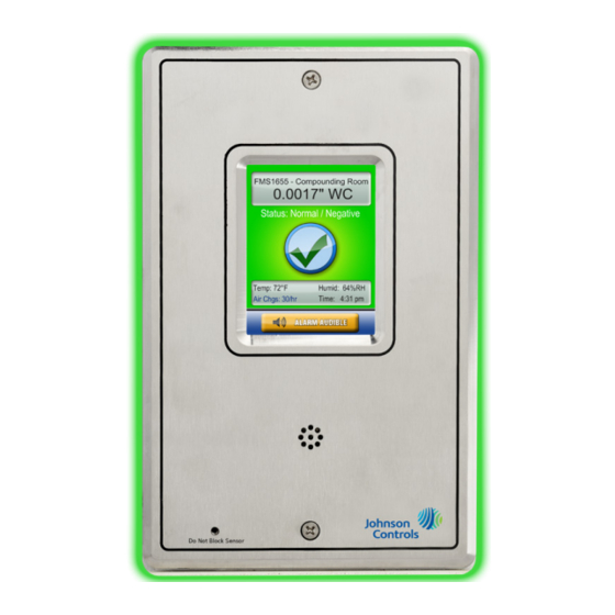
Main Display Screen (Single Sensor Models) All FMS-1655L units are shipped from the factory in the neutral isolation mode, which is represented by a blue screen with a slashed circle. The information that is displayed on the... -
Page 32: Configuring Isolation Room Controller
FMS-1655L. space. The final step in setting up the FMS-1655L is to configure the analog output used to control the damper actuator in the monitored isolation... -
Page 33: Setting Up The Analog Output
Basic Programming Changing the Isolation Mode been forgotten, there is a factory-default The FMS-1655L can be set for positive, password that will provide unrestricted access negative, or neutral modes of isolation. To to the user menu system. Please consult the... -
Page 34: Built-In Diagnostics
For example, selecting the Analog Inputs option to perform a Factory Restore of the option from the Real-Time View menu invokes FMS-1655L. The About This FMS option on the real-time view configuration screen. To the Diagnostics menu provides information skip to the next set of resources to view, tap specific to this particular unit, including the Next button. -
Page 35: Module Settings
Sensor Mode OFF = Single ON = Dual Test Mode OFF = Disabled ON = Enabled Product Type OFF = FMS-1655L ON = HMS-1655L Operational Mode OFF = Demo Mode ON = Run Mode Pushbutton Switch (SW1) Reset Button Pushbutton Switch (SW2): Options Configuration Due to continuous improvement, JCI reserves the right to change product specifications without notice. - Page 36 MODULE SETTINGS Module Settings JCI reserves the right to change product specifications without notice.
-
Page 37: Cleaning The Display
Main Setup Menu can be accessed. Automatically reverts back to audible mode when alarm condition is removed. Hot-Spot Features of FMS-1655L Touchscreen Display (Single sensor model) Due to continuous improvement, JCI reserves the right to change product specifications without notice. -
Page 38: Flow Diagrams
FLOW DIAGRAMS Complete Flow Diagram... - Page 39 FLOW DIAGRAMS Setup Menu...
- Page 40 FLOW DIAGRAMS Setup Menu...
- Page 41 LB-FMS1655L-S01 Code No. LIT-12013118, Rev. A LB-FMS1655L-S02 LB-FMS1655L-T01 Issued August 2018 LB-FMS1655L-T02 +1-414-524-1200 Johnson Controls 5757 N. Green Bay Ave. P.O. Box 591 Milwaukee, WI 53201 JCI CMS-1655 Central Monitoring Station JCI FMS-1655 The Next Generation in Critical Airflow Controls...
Need help?
Do you have a question about the FMS-1655L and is the answer not in the manual?
Questions and answers