Table of Contents
Advertisement
Quick Links
Advertisement
Table of Contents

Subscribe to Our Youtube Channel
Related Manuals for Pfeiffer Vacuum PM Z01 290


Summary of Contents for Pfeiffer Vacuum PM Z01 290
- Page 1 OPERATING INSTRUCTIONS Translation of the Original VENTING VALVE...
- Page 2 These operating instructions describe all models and variants of your product. Note that your product may not be equipped with all features described in this document. Pfeiffer Vacuum constantly adapts its products to the latest state of the art without prior notice. Please take into account that online operating instructions can deviate from the printed operating instructions supplied with your product.
-
Page 3: Table Of Contents
Table of contents Table of contents About this manual Validity 1.1.1 Applicable documents 1.1.2 Variants Target group Conventions 1.3.1 Instructions in the text 1.3.2 Pictographs 1.3.3 Stickers on the product 1.3.4 Abbreviations Safety General safety information Safety instructions Safety precautions Proper use Foreseeable misuse Personnel qualification... - Page 4 List of tables List of tables Tbl. 1: Applicable documents Tbl. 2: Stickers on the product Tbl. 3: Abbreviations used in this document Tbl. 4: Parameter settings in the electronic drive unit of the turbopump Tbl. 5: Factory settings for delayed venting in turbopumps Tbl.
- Page 5 List of figures List of figures Fig. 1: Position of the stickers on the product Fig. 2: Layout of venting valve Fig. 3: Example: Connecting the venting valve to HiPace and TC 110 Fig. 4: Example: Connecting the venting valve to HiPace and TC 400 Fig.
-
Page 6: About This Manual
Keep the manual for future consultation. 1.1 Validity This operating instructions is a customer document of Pfeiffer Vacuum. The operating instructions de- scribe the functions of the named product and provide the most important information for the safe use of the device. The description is written in accordance with the valid directives. The information in this op- erating instructions refers to the product's current development status. -
Page 7: Stickers On The Product
This section describes all the stickers on the product along with their meaning. Rating plate (example) The rating plate is located on the valve housing D-35641 Asslar Mod.: Venting valve Mod.-Nr.: PM Z01 290 -T Input: 24 V DC Made in Germany 2020/05 Tbl. 2: Stickers on the product Fig. -
Page 8: Safety
Safety 2 Safety 2.1 General safety information The following 4 risk levels and 1 information level are taken into account in this document. DANGER Immediately pending danger Indicates an immediately pending danger that will result in death or serious injury if not observed. ►... -
Page 9: Proper Use
► Do not carry out your own conversions or modifications on the unit. 2.4 Proper use ► Use the venting valve only for controlled venting on the designated Pfeiffer Vacuum turbopumps. 2.5 Foreseeable misuse Improper use of the product invalidates all warranty and liability claims. Any use that is counter to the purpose of the product, whether intentional or unintentional, is regarded as improper use, in particular: ●... -
Page 10: Product Description
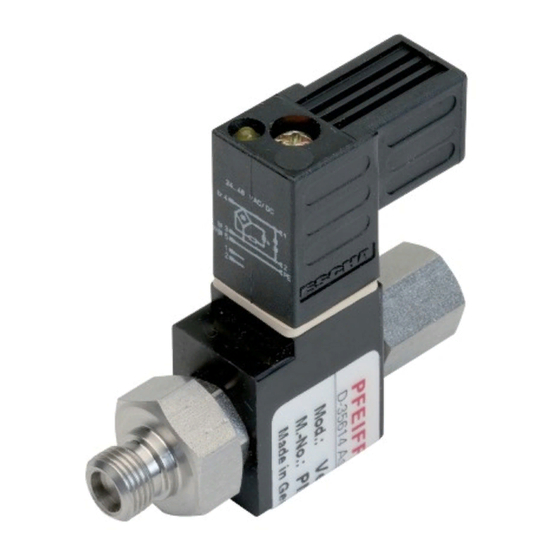
Product description 3 Product description 3.1 Function The Pfeiffer Vacuum venting valve ensures automatic venting of a turbopump after shutting down or in the event of a power failure. Fig. 2: Layout of venting valve 1 LED control lamp Gas inlet, internal thread G 1/8”... -
Page 11: Installation
Using unfiltered media for the gas inlet of a vacuum pump may result in particle contamination. There is a risk of damage to, and even destruction of, vacuum components. ► Install suitable filters from the Pfeiffer Vacuum accessories range upstream of the gas inlet, be- fore you use ambient air or other unclean media. -
Page 12: Fig. 4: Example: Connecting The Venting Valve To Hipace And Tc 400
Installation Fig. 4: Example: Connecting the venting valve to HiPace and TC 400 1 Sealing ring Venting valve 2 Venting screw Control cable power supply plug Fitting the venting valve 1. Unscrew the venting screw with sealing ring out of the turbopump by hand. 2. -
Page 13: Operation
Important settings and function-related variables are programmed ex factory as parameters of the vac- uum pump electronic drive unit. Each parameter has a three-digit number and a description. Parameter- driven operation and control is supported via Pfeiffer Vacuum displays and control units, or externally via RS-485 using Pfeiffer Vacuum protocol. -
Page 14: Accessories
Accessories 6 Accessories Description Order number Screw-on flange, DN 16 ISO-KF, G 1/8" PM 016 780 -T Push-in fitting for 6 mm tube, G 1/8" PM 016 781 -T Push-in fitting for 8 mm tube, G 1/8" PM 016 782 -T Hose nozzle for 9 mm hose, G 1/8"... -
Page 15: Technical Data And Dimensions
7.1 Technical data Classification Venting Valve, Venting Valve, Venting Valve, Venting Valve Shielded Shielded Shielded Part number PM Z01 290 PM Z01 291 PM Z01 292 PM Z01 293 Connection flange G 1/8" G 1/8" G 1/8" G 1/8" (in) Connection flange G 1/8"... -
Page 16: Dimensions
Technical data and dimensions 7.2 Dimensions 24.5 13.9 55.7 62.7 Fig. 5: Dimensions of venting valve with straight power supply plug G1/8" SW17 SW13 G1/8" Fig. 6: Dimensions of venting valve M12 with angled power supply plug Dimensions in mm 16/18... -
Page 17: Declaration Of Conformity
Harmonized standards and applied national standards and specifications: DIN EN 61000-3-2 : 2014 DIN EN 61000-3-3 : 2013 DIN EN 61326-1 : 2013 DIN VDE 0580 : 2011 Signature: Pfeiffer Vacuum GmbH Berliner Straße 43 35614 Asslar Germany (Daniel Sälzer) Aßlar, 2020-04-28...
Need help?
Do you have a question about the PM Z01 290 and is the answer not in the manual?
Questions and answers