Pfeiffer Vacuum TPG 500 Operating Instructions Manual
Total pressure measuring and control unit
Hide thumbs
Also See for TPG 500:
- Installation instructions manual (100 pages) ,
- Operating manual (78 pages) ,
- Operating instructions manual (50 pages)

Related Manuals for Pfeiffer Vacuum TPG 500


Summary of Contents for Pfeiffer Vacuum TPG 500
- Page 1 OPERATING INSTRUCTIONS Translation of the Original TPG 500 Total pressure measuring and control unit...
- Page 2 Dear Customer, Thank you for choosing a Pfeiffer Vacuum product. Your new total pressure measuring and control unit should support you in your individual application with full performance and without malfunctions. The name Pfeiffer Vacuum stands for high-quality vacuum technology, a comprehensive and complete range of top-quality products and first-class service.
-
Page 3: Table Of Contents
Proper use Foreseeable improper use Responsibilities and warranty Owner requirements Personnel qualification 2.8.1 Ensuring personnel qualification 2.8.2 Personnel qualification for maintenance and repair 2.8.3 Advanced training with Pfeiffer Vacuum Operator requirements Product description Structure Display elements Controls Interfaces 3.4.1 Mains connection 3.4.2 Ground terminal... - Page 4 Table of contents Operation Basic operation Measuring with the TPG 500 7.2.1 Gas type dependence 7.2.2 Validity of the display 7.2.3 Accuracy of the measured value display 7.2.4 Calibration Relation: measuring signal and pressure 7.3.1 Conversion for Pirani gauges 7.3.2 Conversion for Penning gauges on measuring board CP 300 C9 7.3.3 Conversion for Penning gauges on measuring board CP 300 C10...
- Page 5 List of tables List of tables Tbl. 1: Applicable documents Tbl. 2: Variants Tbl. 3: Abbreviations used Tbl. 4: Controls Tbl. 5: Switching functions Tbl. 6: Status of the Ethernet connection Tbl. 7: Description of the controls Tbl. 8: Constants for converting measuring signal and pressure Tbl.
- Page 6 List of figures List of figures Fig. 1: Disconnect device in accordance with EN 61010-1 Fig. 2: Front panel Fig. 3: Connections on the rear side Fig. 4: Display elements of the device Fig. 5: Parameter or bar graph Fig. 6: Switch-points 1–4, parameter mode and input lock Fig.
-
Page 7: About This Manual
Variants You can find the part number on the rating plate of the product. Pfeiffer Vacuum reserves the right to make technical changes without prior notification. The figures in this document are not to scale. Dimensions are in mm unless stated otherwise. -
Page 8: Conventions
This section describes all the stickers on the product along with their meaning. Rating plate The rating plate is located on the side of the device. D-35614 Asslar Mod. TPG 500 PT G28 500 xxxxxxxxx Input 100-240 V AC 50-60 Hz 65 W... -
Page 9: Trademark Proof
About this manual Abbreviation Explanation Penning Temperature-dependent resistor (positive temperature coefficient) Setpoint (switch-point) UART Universal asynchronous receiver transmitter (electronic switching to establish digital serial interfaces) Tbl. 3: Abbreviations used 1.4 Trademark proof ● Windows ® and Internet Explorer ® are trademarks of Microsoft Corporation. ●... -
Page 10: Safety
2.2 Safety instructions Safety instructions according to product’s life stages All safety instructions in this document are based on the results of a risk assessment. Pfeiffer Vacuum has taken into account all the relevant life stages of the product. 10/76... -
Page 11: Fig. 1: Disconnect Device In Accordance With En 61010-1
Safety Danger to life due to electric voltage DANGER Danger to life due to electric voltage High voltages are present inside the device. When touching parts that are live, there is a risk of death. If there is visible damage, there is a risk of death when commissioning the device. ►... - Page 12 ► Only operate the device in a dry environment. ► Operate the device away from fluids and humidity sources. ► Do not switch on the device if fluid has penetrated into it, instead contact Pfeiffer Vacuum Serv- ice. ► Always disconnect the current supply before cleaning the device.
-
Page 13: Safety Precautions
Safety WARNING Health hazards due to cleaning agent The cleaning agent being used causes health hazards which could include, for example, poisoning, allergies, skin irritations, chemical burns or damage to the airways. ► When handling cleaning agents, observe the applicable regulations. ►... -
Page 14: Proper Use
● Use with replacement or accessory parts that are unsuitable or are not approved 2.6 Responsibilities and warranty Pfeiffer Vacuum shall assume no responsibilities and warranty if the operating company or a third party: ● disregards this document ● does not use the product for its intended purpose ●... -
Page 15: Ensuring Personnel Qualification
─ Customer with Pfeiffer Vacuum service training ─ Pfeiffer Vacuum service technician 2.8.3 Advanced training with Pfeiffer Vacuum For optimal and trouble-free use of this product, Pfeiffer Vacuum offers a comprehensive range of courses and technical trainings. For more information, please contact Pfeiffer Vacuum technical training. -
Page 16: Operator Requirements
4. Comply with the application limits. 5. Observe the technical data. 6. Please contact the Pfeiffer Vacuum Service Center if your questions on operation or maintenance of the product are not answered by these operating instructions. – You can find information in the Pfeiffer Vacuum service area. -
Page 17: Product Description
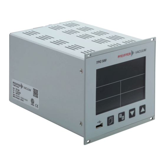
Product description 3 Product description 3.1 Structure Fig. 2: Front panel 1 Display USB connection (type A) 2 Controls Fig. 3: Connections on the rear side 1 Plug-in position A for a measuring board Ethernet interface 2 Plug-in position B for a measuring board Ground terminal 3 Plug-in position C for an interface board and relay board USB connection (type B) -
Page 18: Display Elements
Product description 3.2 Display elements Display text in this manual Both lines of the display text are separated in this manual by a vertical dash (Line 1 | Line Display elements of the device 0...5V Micronmbar 0...10V AVmTorrhPa 4...20mA Fig. 4: Display elements of the device 1 Parameter or bar graph Measuring channel status (measuring channel B1 and B2) -
Page 19: Controls
Product description Switch-points 1–4, parameter mode and input lock Fig. 6: Switch-points 1–4, parameter mode and input lock 1 Switching function activated (number lights up) Input lock activated 2 Switching function deactivated (number does not light up) Relay off (symbol does not light up) 3 Parameter mode activated Relay on (symbol lights up) Measurement channel status... -
Page 20: Interfaces
Product description 3.4 Interfaces 3.4.1 Mains connection DANGER Danger to life from electric shock Inadequate or incorrect grounding of the unit leads to contact-sensitive voltage on the housing. When making contact, increased leakage currents will cause a life-threatening electric shock. ► Before the installation, check that the connection leads are voltage-free. ►... -
Page 21: Rs-485" Connection
Product description Fig. 9: "CONTROL" connection (25-pole D-Sub socket) Ground (GND) +24 V (DC), 100 mA 18, 20, 22, 24 Analog ground (AGND) 7, 8, 16 Switching function 1 Analog output 1 4, 5, 13 Switching function 2 Analog output 2 1, 2, 10 Switching function 3 Analog output 3... -
Page 22: Usb" Connection (Type B)
Status of the Ethernet connection 3.5 Identifying the product You will need all the data from the rating plate to safely identify the product when communicating with Pfeiffer Vacuum. 1. Read the data on the product rating plate. 2. Record this data. -
Page 23: Scope Of Delivery
Product description 3.6 Scope of delivery The scope of delivery includes the following parts: ● Total pressure measuring and control unit ● Accessory kit ─ 4 × collar screws and synthetic nipple ─ 1 rubber strip ─ 2 self-adhesive rubber feet ─... -
Page 24: Transport And Storage
Transport and storage 4 Transport and storage 4.1 Transporting the product NOTICE Damage caused by incorrect transportation Transportation in unsuitable packaging, or failure to install all transport locks, can damage the prod- uct. ► Comply with the instructions for safe transportation. Packing We recommend keeping the transport packaging and original protective cover. -
Page 25: Installation
Installation 5 Installation You can install the unit in three ways: ● in a 19” rack ● in a switchboard ● as a desktop unit Observe the prescribed ambient conditions ► Install and operate the unit within the permissible ambient conditions (see chapter “Technical da- ta”, page 69). -
Page 26: Installing The Device In A Switchboard
Installation Fig. 16: Device installation Installing the device in the rack module adapter Required tools ● Screwdriver Required material ● 4 × collar screws and synthetic nipple ● Slide rails (optional) 1. Recommendation: Install the slide rails in the rack frame for safe and easy installation of heavy rack module adapters. -
Page 27: Using The Device As A Desktop Device
Installation M3 or Ø3.5 Fig. 17: Required control panel cut-out Installing the device in a switchboard Required tool ● Screwdriver Required material ● 4 screws (M3 or equivalent) 1. Support the device from below to relieve the front panel. 2. Push the device into the control panel cut-out. 3. -
Page 28: Establishing A Grounding Connection
Installation Using the device as a desktop device You can use the device as a desktop device. The shipment includes two self-adhesive rubber feet as well as an attachable rubber strip, for this purpose. Required material ● 2 self-adhesive rubber feet ●... -
Page 29: Fitting The Device With Plug-In Boards
5.6 Fitting the device with plug-in boards Installing plug-in boards In most cases, Pfeiffer Vacuum supplies the TPG 500 ready for operation with installed plug-in boards. You can find information on the installing or replacing plug-in boards in the operating instructions with document number BG 5972 for the plug-in boards. -
Page 30: Commissioning
(COM) to an IP address. You can access the virtual COM interfaces using every program that supports series interfaces (e.g. terminal program, LabView, etc.). Depending on the protocol setting, communication with the device is either via the Mnemonic or Pfeiffer Vacuum protocol. 30/76... -
Page 31: Fig. 20: Ethernet Configuration Tool
1. Recommendation: Contact your network administrator before you start the configuration. 2. Recommendation: Update the operating system before you start the Ethernet configuration. You also require administrator rights. 3. Open the Pfeiffer Vacuum Download Center in the browser. 4. Enter "Ethernet Configuration Tool" as the keyword. -
Page 32: Operation
Description of the controls 7.2 Measuring with the TPG 500 7.2.1 Gas type dependence Pfeiffer Vacuum has calibrated the measured value display to Nitrogen N at the factory. The measured value display of the device depends on the gas type. Characteristics for other gases... -
Page 33: Calibration
< 10 hPa. 7.2.4 Calibration Pfeiffer Vacuum has calibrated the gauge to standard values at the factory. You do not need to calibrate cold cathode measuring circuits. Calibrating the Pirani measuring circuit Information regarding calibration of the Pirani measuring circuit can be found in the operat- ing instructions for the plug-in boards. -
Page 34: Tbl. 8: Constants For Converting Measuring Signal And Pressure
Operation 100000 10000 1000 Torr 0.01 0.001 0.0001 0.00001 4000 6000 8000 10000 12000 14000 16000 18000 20000 I [µA] Fig. 22: Measuring signal 4 – 20 mA and pressure for Pirani gauges Converting measuring signal and pressure ► Convert analog output voltage into pressure: (0.7 ×... -
Page 35: Conversion For Penning Gauges On Measuring Board Cp 300 C9
Operation Measuring signal (output current I) Pressure (p) Constant (d) [mA] [hPa] 1.778 × 10 [mbar] [Pa] 1.778 × 10 [kPa] 1.778 × 10 [Torr] 1.334 × 10 mTorr 1.334 × 10 Tbl. 9: Constants for converting measuring signal and pressure 7.3.2 Conversion for Penning gauges on measuring board CP 300 C9 0.01 Torr... -
Page 36: Tbl. 10: Constants For Converting Measuring Signal And Pressure
Operation 0.01 Torr 0.001 0.0001 0.00001 0.000001 0.0000001 1E-08 1E-09 1E-10 4000 6000 8000 10000 12000 14000 16000 18000 20000 I [µA] Fig. 24: Measuring signal 4 – 20 mA and pressure for Penning gauges on measuring board CP 300 C9 Converting measuring signal and pressure ►... -
Page 37: Conversion For Penning Gauges On Measuring Board Cp 300 C10
Operation Measuring signal (output current I) Pressure (p) Constant (d) [mA] [hPa] 1.778 × 10 [mbar] [Pa] 1.778 × 10 [kPa] 1.778 × 10 [Torr] 1.334 × 10 mTorr 1.334 × 10 Tbl. 11: Constants for converting measuring signal and pressure 7.3.3 Conversion for Penning gauges on measuring board CP 300 C10 0.01 Torr... -
Page 38: Tbl. 12: Constants For Converting Measuring Signal And Pressure
Operation 0.01 Torr 0.001 0.0001 0.00001 0.000001 0.0000001 1E-08 1E-09 1E-10 1E-11 4000 6000 8000 10000 12000 14000 16000 18000 20000 I [µA] Fig. 26: Measuring signal 4 – 20 mA and pressure for Penning gauges on measuring board CP 300 C10 Converting measuring signal and pressure ►... -
Page 39: Conversion For Penning Gauges On Measuring Board Cp 300 T11
Operation Measuring signal (output current I) Pressure (p) Constant (d) [mA] [hPa] 1.000 × 10 [mbar] [Pa] 1.000 × 10 [kPa] 1.000 × 10 [Torr] 7.500 × 10 mTorr 7.500 × 10 Tbl. 13: Constants for converting measuring signal and pressure 7.3.4 Conversion for Penning gauges on measuring board CP 300 T11/T11L 0.01 Torr... -
Page 40: Tbl. 14: Constants For Converting Measuring Signal And Pressure
Operation 0.01 Torr 0.001 0.0001 0.00001 0.000001 0.0000001 1E-08 1E-09 1E-10 1E-11 1E-12 4000 6000 8000 10000 12000 14000 16000 18000 20000 I [µA] Fig. 28: Measuring signal 4 – 20 mA and pressure for Penning gauges on measuring board CP 300 T11/T11L Converting measuring signal and pressure ►... -
Page 41: Operating Modes
Operation Measuring signal (output current I) Pressure (p) Constant (d) [mA] [hPa] 5.620 × 10 [mbar] [Pa] 5.620 × 10 [kPa] 5.620 × 10 [Torr] 4.215 × 10 mTorr 4.215 × 10 Tbl. 15: Constants for converting measuring signal and pressure 7.4 Operating modes The device operates in the following modes: ●... -
Page 42: Measured Value Display
Operation > 1s > 1s Fig. 30: Switching the measuring circuit on and off Procedure ► Recommendation: Only switch cold cathode gauges on with pressures < 10 hPa in order to avoid excessive contamination. ► Recommendation: Where possible, switch cold cathode gauges off in order to avoid excessive contamination. -
Page 43: Identifying Measuring Board And Gauge
Operation Fig. 31: Measuring range 7.5.4 Identifying measuring board and gauge The device reads the gauge identification (line 1) and the gauge type (line 2) for the current measure- ment channel and displays it for 5 seconds Fig. 32: Identifying measuring board and gauge Procedure ►... -
Page 44: Parameter Mode
Operation Loading factory settings ► Hold both arrow keys pressed > 5 seconds. – The device loads the factory settings. – “DEFAULTS LOADED” appears. 7.6 Parameter mode Parameter mode is the operations mode for displaying and changing/entering parameter values, testing the device and saving measured data. Parameter groups exist for better structuring. Parameter groups ●... -
Page 45: Switching Function Parameters
Setting the threshold values Pfeiffer Vacuum recommends setting the upper threshold value 1/2 decade above the low- er threshold value or the lower threshold value 1/2 decade below the upper threshold val-... -
Page 46: Gauge Parameters
Operation SP 1 H SP 1 L Time t Fig. 35: Switching functions and threshold values 7.6.2 Gauge parameters Parameter Description FILTER Measured value filter NAME Measuring point name Tbl. 19: Gauge parameters The gauge parameters group includes displaying and editing/inputting gauge-related parameters. FILTER The measured value filter permits a better evaluation of measurement signals with fluctuation or inter- ference. -
Page 47: Gauge Control
Operation Fig. 36: Filter: OFF, 10 Hz, 1 Hz (from left to right) NAME Measuring point name with a maximum 8 characters. Only uppercase letters, blank spaces and num- bers are permitted. ● A1 Sensor A1 (ex factory) 7.6.3 Gauge control Parameter Description SENSOR ON... -
Page 48: General Parameters
Operation This parameter is only displayed if you have set the activation type to "SENSOR A1", "SENSOR A2", "SENSOR B1" or "SENSOR B2". Prerequisite ● "THRESHOLD OFF" ≥ "THRESHOLD ON" Defining the activation threshold value ► Define an activation threshold value with the parameter "THRESHOLD ON". –... - Page 49 Operation ● Pa ● Micron (= 0.001 Torr) (only available if the Torr lock is not activated.) ● Volt ● Ampere, amp ANALOG OUTPUT The "ANALOG OUTPUT" parameter defines the output characteristic of the 4 analog outputs. ● OFF Disabled (factory setting) ●...
- Page 50 Operation BARGRAPH / GRAPH The display can show a bargraph or the measured pressure as a function of time (p = f ). During pa- rameter setting, the parameter and the parameter value are displayed here. ● OFF Disabled (factory setting) ●...
-
Page 51: Communication Parameters
Operation SCREENSAVER You can set the screensaver for different time periods. The "DARKROOM" setting will switch off the background lighting completely after 1 minute. ● Off (ex factory) ● 10 minutes ● 30 minutes ● 1 hour ● 2 hours ●... -
Page 52: Data Logger Mode
● 1 – 24 (ex factory = 1) PROTOCOL The "PROTOCOL" parameter defines the protocol of the serial interface (RS-485, USB-B, Ethernet). ● AUTOMATIC Automatic detection (ex factory) ● PFEIFFER VACUUM Pfeiffer Vacuum protocol ● MNEMONIC 3 CHAR Mnemonics protocol DHCP (ETH) The "DHCP (ETH)"... -
Page 53: Tbl. 23: Parameters In Data Logger Mode
The device does not recognize all USB storage media automatically, for instance if they do not comply with the USB standard. Try using a different storage medium first before con- tacting your nearest Pfeiffer Vacuum Service Center. MODE The "MODE" parameter defines the start of data recording. -
Page 54: Setup Mode
Operation ● Point ● Comma FILENAME The "FILENAME" parameter defines the name of the measured data file. Defining the name of the measured data file 1. Define the name of the measured data file with a max. 8 characters. – The file extension is CSV. 2. -
Page 55: Test Parameters
Operation ● RUNNING The device saves the CSV file. ● DONE The saving process is complete. RESTORE FROM The "RESTORE FROM" function loads all parameters from a USB storage medium onto the device. Selecting a file name ► Select a file name between SETUP01 and SETUP99. ●... - Page 56 < SOFTWARE VERSION The "SOFTWARE VERSION" function shows the firmware version (program version). This information is useful if you need to contact Pfeiffer Vacuum. HARDWARE VERSION The "HARDWARE VERSION" function shows the hardware version. This information is useful if you need to contact Pfeiffer Vacuum.
- Page 57 Testing the display 1. Press both arrow keys simultaneously. – When the test is initiated, all display elements light up simultaneously for 10 seconds. 2. Contact Pfeiffer Vacuum Service in the event of any errors. RELAY TEST NOTICE Unintentional results with controller connected Switch relay not dependent on pressure.
-
Page 58: Decommissioning
Decommissioning 8 Decommissioning Switching the device off 1. Switch off the device at the mains switch. 2. For rack assembly: Switch off the device centrally via the switched mains distributor. 3. Wait at least 10 seconds before switching it back on again, so that the device can reinitialize. 58/76... -
Page 59: Maintenance
► Only operate the device in a dry environment. ► Operate the device away from fluids and humidity sources. ► Do not switch on the device if fluid has penetrated into it, instead contact Pfeiffer Vacuum Serv- ice. ► Always disconnect the current supply before cleaning the device. -
Page 60: Replacing The Battery
9.3 Updating the firmware Procedure ► Contact your nearest Pfeiffer Vacuum Service Center if your device requires a more recent firm- ware version, in order to support new gauges for example. ► Update the firmware of your device using a USB storage medium (USB type A on the front side of the device). - Page 61 Prerequisite ● Microsoft Windows XP, 7, 8 or 10 operating system ● No USB storage medium connected to the front side of the device 1. Open the Pfeiffer Vacuum Download Center in the browser. 2. Enter "USB Update Tool" as the keyword.
-
Page 62: Fig. 37: Usb Update Tool
Maintenance Fig. 37: USB Update Tool 62/76... -
Page 63: Malfunctions
The error appears and the error relay opens ("CONTROL" connection). Error cannot be eliminated If the error persists even after it has been acknowledged and/or the gauge has been re- placed several times, contact your nearest Pfeiffer Vacuum Service Center. Error Possible cause... -
Page 64: Shipping
► Comply with the instructions for safe distribution. Decontamination subject to charge Pfeiffer Vacuum decontaminates products not clearly declared "Free of contamination" at your expense. Instructions for safe shipping ► Do not ship microbiological, explosive or radioactively contaminated products. -
Page 65: Recycling And Disposal
– Potentially contaminated components that come into contact with media 12.2 Dispose of a total pressure measuring and control unit Pfeiffer Vacuum total pressure measuring and control units contain materials that you must recycle. 1. Dismantle the electronic components. 2. Separate the components into recyclable materials. -
Page 66: Service Solutions By Pfeiffer Vacuum
We are always focused on perfecting our core competence – servicing of vacuum components. Once you have purchased a product from Pfeiffer Vacuum, our service is far from over. This is often exactly where service begins. Obviously, in proven Pfeiffer Vacuum quality. - Page 67 Service solutions by Pfeiffer Vacuum 5. Prepare the product for transport in accordance with the provisions in the contamination declaration. a) Neutralize the product with nitrogen or dry air. b) Seal all openings with blind flanges, so that they are airtight.
-
Page 68: Accessories
Measurement cable in standard and high temperature versions in different lengths, for connecting to a Pfeiffer Vacuum total pressure measuring and control unit or an ionization measuring device Dummy plates Cover plate for free slots on Pfeiffer Vacuum total pressure measuring and control units that are not fully configured 14.2 Ordering accessories... -
Page 69: Technical Data And Dimensions
Technical data and dimensions 15 Technical data and dimensions 15.1 General mbar Torr | mm Hg mbar 1 · 10 0.75 1000 1000 1 · 10 0.01 0.01 1 · 10 1 · 10 7.5 · 10 0.75 1 · 10 0.01 1000 Torr | mm Hg 1.33... -
Page 70: Tbl. 34: Ambient Conditions
Technical data and dimensions Parameter Value Pollution degree Protection degree IP30 Tbl. 34: Ambient conditions Parameter Value Quantity, number 2 for measuring boards (A and B) 1 for interface board and relay board (C) Connectable measuring Pirani: PI 300D, PI 300 DN boards Cold cathode: PE 300DC9 Pirani/cold cathode: CP 300C9, CP 300C10, CP 300T11, CP... -
Page 71: Tbl. 39: Relay Contacts
Reversible analog outputs Parameter Value PROTOCOL ASCII, addressable (RS485), Mnemonics protocol or Pfeiffer Vacuum protocol Data format Two-way data traffic, 1 start bit, 8 data bits, 1 stop bit, no parity bit, no handshake Baudrate 9600, 19200, 38400, 57600, 115200... -
Page 72: Dimensions
Technical data and dimensions 15.3 Dimensions 141.9 ≈ 270 137.5 Fig. 38: Dimensions Dimensions in mm 72/76... -
Page 73: Etl Certification
ETL LISTED The product TPG 500 - conforms to the following UL standards UL 61010-1:2012 Ed. 3 + R:21 Nov 2018 Safety requirements for electrical equipment for measurement, control and laboratory use Part 1: General requirements UL 61010-2-030:2012 Ed. 1 + R:16 Sep 2016... -
Page 74: Declaration Of Conformity
Declaration of conformity Declaration for product(s) of the type: Total pressure measuring and control unit TPG 500 We hereby declare that the listed product satisfies all relevant provisions of the following European Directives. Low voltage 2014/35/EC Electromagnetic compatibility 2014/30/EU Restriction of the use of certain hazardous substances 2011/65/EU... - Page 75 75/76...
Need help?
Do you have a question about the TPG 500 and is the answer not in the manual?
Questions and answers