Table of Contents
Advertisement
Advertisement
Table of Contents

Related Manuals for Pfeiffer Vacuum TCP 3000


Summary of Contents for Pfeiffer Vacuum TCP 3000
-
Page 1: Manufacturer´s Declaration
Betriebsanleitung • Operating Instructions Electronic Drive Unit TCP 3000... -
Page 2: Table Of Contents
3.12. Connecting the RS-232 interface ........10 10. Technical Data ........24 4. Operating And Display Elements ..11 10.1. Data list for TCP 3000 Electronic Drive Unit....24 4.1. Operating elements ............11 10.2. Dimension diagram............24 4.2. Display elements.............. 12 11. -
Page 3: Important Notes For Your Safety
– Hazards caused by the unit. – Hazards caused by your system. ☞ Note the safety and accident prevention regulations. ☞ Regularly check compliance with all safety measures. ☞ Install the TCP 3000 while maintaining the specified Warning, risk of suffering injury. WARNING ambient conditions. -
Page 4: Getting To Know Your Tcp 3000
– Turbomolecular pump (“Pump”) Fore vakuumflange Proper Use Vent connection – The TCP 3000 electronic drive unit must be used only in Electrical connection connection with special pumps from PFEIFFER-VACUUM (see section 10 “Technical Data”). – Compliance with installation, commissioning, operating and maintenance instructions must be ensured. -
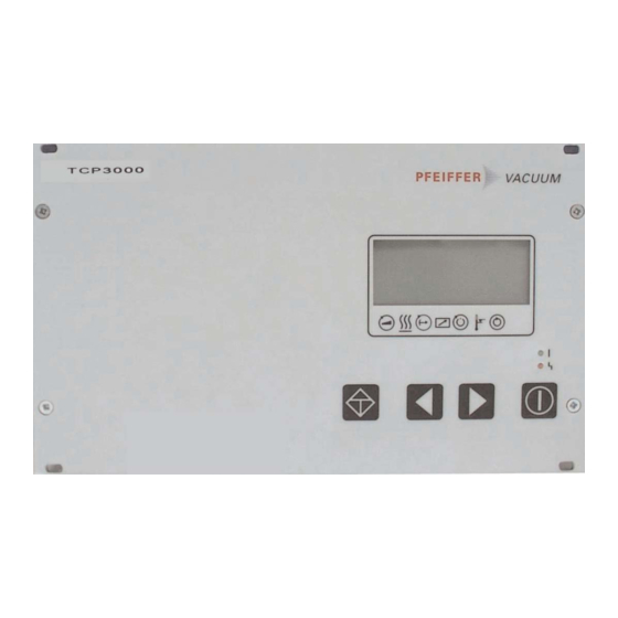
Page 5: Description Of Front Panel
2.3. Description of the Front Panel 2.5. General Description of the Unit All controls and display components are located on the front The electronics of the TCP 3000 electronic drive unit provides panel. for a number of monitoring and control options for turbomole- cular pumps and for the pumping process. -
Page 6: Installation
Cooling/Air Circulation The drive electronics of the TCP 3000 generates heat at an 1 phase, 2 2 3 3 0 0 V V ~ ~ ( ( ± ± 1 1 0 0 % % ) ) 3 phase, 2 2 0 0 8 8 V V 3 3 ~ ~ ( ( + + 2 2 0 0 / / - - 1 1 0 0 % % ) ) amount equivalent. -
Page 7: Constructional Protection
➡ Connect the pump using the connecting cable (52) to the ➡ Connect the control cable of the vent valve to the control socket marked PUMP on the TCP 3000. cable “Vent” X8 of the pump cable. ➡ Lock the bayonet catch (51, 53) after plugging in. After locking both seals must be secured with the delivered set screws. -
Page 8: Connecting The Cooling Water Monitor
11 at the TCP 3000. A distinction is made between digital and analog inputs and ➡ Connect the cooling water monitor to the remote plug 11 outputs. -
Page 9: Pin Arrangement Remote
Plug Arrangement REMOTE Pin Description/Explanation Function Type + 24 V DC Reference voltage for all remote inputs and outputs (potential free) Venting release Release “vent pump” Digital input ON/OFF The pump is vented according to the “Vent mode P030” setting (static signal) Motor TMP Switches the turbo pump drive on... -
Page 10: Connecting The Rs-485 Interface
5:D+, 7:D– Level converter 1..8 “Service” pinout Assignment reserved 1) reserved 1) RS-232 RxD RS-232 TxD reserved 1) reserved 1) reserved 1) 1) Caution! No connections may be run to these pins. They are only used by PFEIFFER VACUUM Service! -
Page 11: Operating And Display Elements
4. Operating And Display Elements 4.1. Operating Elements The four push-buttons on the front panel have the following functions: Push-Button Application/Example Explanation Reset (malfunction acknowledgement) acknowledges malfunctions (red LED illuminates) 309: Act rotspd Scroll Parameters Backwards 310: TMP I-Mot scrolls a parameter backwards 50% ... -
Page 12: Display Elements
4.2. Display Elements Symbol Definitions Symbol Meaning Display Explanation LC Display Pump – accelerates 721: Vent time Line 1 120 s Line 2 data not changed Line 3 function Line 4 Symbols Standby – The display of the functions is shown via a four line LC display. -
Page 13: Abbreviated Overview, Operating
4.3. Abbreviated Overview, Operating 4.4. Operating Examples Switching on the electronic drive unit ➡ Make connection to the mains. Switching on the pumping station ➡ Select «7 7 9 9 4 4 : : P P a a r r a a m m . . S S e e t t ». ➡... -
Page 14: Illuminated Displays
Illuminated Displays The red LEDs (error status) and green LEDs (operations status) on the front panel can assume the following conditions: R R e e d d L L E E D D G G r r e e e e n n L L E E D D Illuminates: Collective error message Mains ON, pumping station ON [P P : : 0 0 1 1 0 0 ]... -
Page 15: Parameters
Numerical modifying of a value To adapt this parameter to the individual requirements of the user the TCP 3000 provides three parameter sets which differ from each other in the number of parameters and their sorting. The respective parameter set can be selected via the parameter «7 7 9 9 4 4 : : P P a a r r a a m m . -
Page 16: Parameters Overview, Tcp 3000, Numerical
= Parameter setting is saved internal and preserves the value if mains is switched off. 1) R = Parameter readable via interface /W = parameter writeable via interface. 2) See Interface instruction ”Pfeiffer vacuum Protocol to RS-232 and -485” / PM 800 488 BN 3) Function can only be affected via remote plug 4) Effective only after mains ON/OFF * Parameters are not shown in the LC display but displayed by symbols (line 4) or operable by the keys. -
Page 17: Parameters Overview, Operation Oriented
5.3. Parameter overview TCP 3000, operation oriented Display Name, Description fact. set. RS 485 Sect. Run up time and switch point • RUTime ctr Run-up time monitoring ON/OFF • TMP RUTime Maximum run-up time in mins • Switch pnt Switchpoint... -
Page 18: Operations
➡ Select [ [ P P : : 7 7 1 1 7 7 ] ] «Stbyrotset». ➡ Set the standby speed within the range 20-100 %. Self test The TCP 3000 performs a self-test. Once the self-test is Standby is recommended during stoppages. This function complete, the unit is ready for operation. -
Page 19: Pump Motor On/Off
If the rotor overheat protection is active the warning message The following functions can be controlled using remote “F F 0 0 3 3 5 5 ” is shown and the red LED illuminates. control (see also “Plug Arrangement REMOTE” table): In accordance to the adjustment of [ [ P P : : 0 0 2 2 7 7 ] ] the drive power –... -
Page 20: Keys Lock
6.14. Configuring the Analog Output The extended parameter set is used to choose between three An analog signal (0-10 V DC) can be tapped at the TCP 3000, venting modes: with the following information: ➡ Call «7 7 9 9 4 4 : : P P a a r r a a m m s s e e t t »; select «1 1 ». -
Page 21: Switching Outputs
6.15. Switching Outputs The following functions are assigned to the switching outputs: Switching output 1: (Remote: Pin 8 and r r e e l l a a y y c c o o n n t t a a c c t t s s w w i i t t c c h h p p o o i i n n t t ) Active high after rotation speed switch point is reached. -
Page 22: Error Messages And Warnings
7. Error Messages and Warnings 7.1. General information 7.2. Errors During Operation Error ("Errxxx" or "Error Exxx") always cause the Errors and warnings occurring during operation are always ACHTUNG turbo pump, fan, heater and backing pump to indicated on the LCD - regardless of the function of the servi- switch off. -
Page 23: What To Do In Case Of Breakdowns
8. What To Do In Case Of Breakdowns? Identifying error messages Error messages shown on the LCD can be identified and, in part, remedied with the aid of the error code table (Chapter 7). The last 10 errors and warnings are stored in the fault memory [P P : : 3 3 6 6 0 0 - - 3 3 6 6 9 9 ] during operation. -
Page 24: Technical Data
10. Technical Data 10.1. Data List For TCP 3000 Electronic Drive Unit Variables Unit TCP 3000 Pumps, driven by TCP 3000 TPH 2303 OnTool Booster 150 Connection voltage (1-phase/L1-N) V AC 230-240 V (±10 %) Connection voltage (3-phase/Lx-Lx) V AC 208-240 V (±10 %) -
Page 25: Wiring Diagram
11. Wiring diagram Wiring diagram of TCP 3000 Pump Remote +24 V DC* Motorphase 1 Motorphase 1 Venting on Motor TMP On Motorphase 1 Motorphase 2 Pumping station on Standby on Motorphase 2 Motorphase 2 n.c. Set rot speed 0-10 V... -
Page 26: Accessories
Description of turbomolecular pump depends on pump type* Turbo pump water cooling Description of water cooling PM 800 546 BE Pfeiffer Vacuum Protocol RS-232/RS-485 Description of interface protocol PM 800 488 BE Venting valve TVF 005 Description of venting valve... - Page 27 Konformitätserklärung Declaration of Conformity im Sinne folgender EG-Richtlinien: pursuant to the following EC directives: - - E E l l e e k k t t r r o o m m a a g g n n e e t t i i s s c c h h e e V V e e r r t t r r ä ä g g l l i i c c h h k k e e i i t t / / E E l l e e c c t t r r o o m m a a g g n n e e t t i i c c C C o o m m p p a a t t i i b b i i l l i i t t y y 2 2 0 0 0 0 4 4 / / 1 1 0 0 8 8 / / E E G G - - N N i i e e d d e e r r s s p p a a n n n n u u n n g g / / L L o o w w V V o o l l t t a a g g e e 2 2 0 0 0 0 6 6 / / 9 9 5 5 / / E E G G Hiermit erklären wir, daß...
- Page 28 Roots Pumps Dry Vacuum Pumps Leak Test Units Valves Flanges, Feedthroughs Vacuum Measurement Gas Analysis System Technology Service Pfeiffer Vacuum Technology AG · Headquarters/Germany Tel. +49-(0) 64 41-8 02-0 · Fax +49-(0) 64 41-8 02-2 02 · info@pfeiffer-vacuum.de · www.pfeiffer-vacuum.net...
Need help?
Do you have a question about the TCP 3000 and is the answer not in the manual?
Questions and answers