
Subscribe to Our Youtube Channel
Related Manuals for Pfeiffer Vacuum TPG 256 A


Summary of Contents for Pfeiffer Vacuum TPG 256 A
- Page 1 Operating manual TPG 256 A Vacuum measurement and control unit for Compact Gauges MaxiGauge™ BG 805 186 BE / B (2005-07)
-
Page 2: Validity
Validity This manual applies to products with part number: • PT G28 760 with serial interfaces RS232C and RS422 • PT G28 761 with serial interfaces RS232C and RS422 and RS485 (addressable, isolated) and RS422 (isolated) The part number can be taken from the nameplate on the rear panel, where the interfaces can be connected as well (→... -
Page 3: Table Of Contents
Contents Validity Firmware Version Trademarks 1 Intended Use 2 Technical Data 3 Safety 4 Commissioning 4.1 Personnel 4.2 Set-Up, Assembly 4.3 Power Connection 4.4 Connecting the Gauges to sensor 4.5 control Control Connector 4.6 RS 232/422 Pinout Connector for Serial Interfaces 4.7 RS 485/422 isol. - Page 4 8.1.2 Connection Cable 8.1.3 Data Transmission 8.2 Mnemonics 8.2.1 Measurement Values 8.2.2 Display 8.2.3 Switching Functions 8.2.4 Parameters 8.2.5 Interfaces 8.2.6 Error Messages 8.2.7 Test Programs for Pfeiffer Vacuum Service Specialists Contents BG 805 186 BE / B (2005-07) MaxiGauge.om...
- Page 5 9 Maintenance and Care 9.1 Personnel 9.2 Cleaning 9.3 Maintenance 10 Accessories and Spare Parts 11 Decommissioning Appendix Validity Table Conversion of Pressure Units Equipment Test Literature Declaration of Conformity For cross references to pages within this manual, the symbol (→ XY) is used, for references to other docu- ments, the symbol (→...
-
Page 6: Intended Use
1 Intended Use The MaxiGauge™ TPG 256 A is a 6-port total pressure measurement and control unit for Pfeiffer Vacuum Com- pact Gauges. The unit has been engineered for use with the following gauge families * • TPR Pirani gauge •... - Page 7 228.5 mm Installed width 207 mm G Installed height 88 mm (2 height units) Figure 2: Pfeiffer Vacuum, D-35614 Asslar Nameplate Typ: F-No: The nameplate is located on the rear panel. Make sure that the voltage and frequency ratings con- form with the local power supply system.
-
Page 8: Technical Data
2 Technical Data Mechanical data → Figure 1 Dimensions Weight 2.1 kg → Accessories, 19" rack installation Power connection Voltage 90 ... 250 VAC / 50 ... 60 Hz Power consumption 60 VA Overvoltage category Protection class Unit connector IEC 320 C14 Power switch Rear panel Environment, standards... - Page 9 Figure 3: Logarithmic gauges Gauges Compact Pirani Gauge (Pirani gauge) Compact Pirani Capacitance Gauge (Pirani/Capacitance gauge) Compact Cold Cathode Gauge (Cold cathode gauge) Compact FullRange™ CC Gauge (Pirani/Cold cathode gauge) Compact Process Ion Gauge (Pirani/High pressure gauge) Compact FullRange™ BA Gauge (Pirani/Bayard-Alpert gauge) Technical data BG 805 186 BE / B...
- Page 10 Compact Capacitance Gauge (Capacitive gauge) Compact Piezo Gauge (Piezoresistive gauge) Gauge connections Number Compatible gauges Pfeiffer Vacuum Compact Gauges (→ [1] ... [15]) TPR 250, TPR 260, TPR 261, Compact Pirani Gauges TPR 265, TPR 280, TPR 281 PCR 260...
- Page 11 → Measured values Measurement ranges Gauge Measurement error ≤0.2 % measurement signal Gain error ≤20 mV Offset error Measurement rate 100 / s Display rate 4 / s Filter time constant 2.1 s = 0.075 Hz) tandard 320 ms (f = 0.5 Hz) 100 ms (f = 1.6 Hz)
- Page 12 Pinout for serial interface RS232C or RS422 (not isolated) relay Connector for relay switch contacts Power inlet 3-pin Reference for fuses inside the unit (replacement only by Pfeiffer Vacuum Service) Power switch sensor 1 ... Connectors for gauges ... sensor 6...
- Page 13 Switching functions Number Gauge assignment User-programmable Response time 10 ms, if the measured value is near the setpoint. For bigger dif- ferences, take the filter time con- stant into consideration. Relay contacts Changeover switch, floating = 60 VDC / I = 3 A = 30 VAC / I = 3 A...
- Page 14 Figure 5: Symbols for residual hazards DANGER Information on preventing any kind of bodily injury or extensive property damage. CAUTION Special information on damage prevention. NOTE Special information on cost-effective use. Figure 6: Symbol for special personal qualifications Specialists This work may only be carried out by persons with suitable technical training and the necessary experi- ence.
-
Page 15: Safety
3 Safety 3.1 Personnel Specialists Work on and with the MaxiGauge™ TPG 256 A may only be carried out by persons with suitable technical training and the necessary experience. 3.2 Danger, Caution, The opposite symbols together with explanatory text are... - Page 16 Figure 7: Setup as desktop unit Make sure to provide for proper ventilation when using the MaxiGauge™ as desktop unit. For this purpose, an acrylic glass stand can be ordered as accessory (→ Accessories 104). Figure 8: Use a con- Connection cable nection cable with ground...
-
Page 17: Commissioning
4 Commissioning 4.1 Personnel Specialists The unit may be put into service by skilled and suitably trained persons only. 4.2 Set-Up, Assembly There are two possibilities for incorporating the unit into a switching cabinet according to DIN 41 494: a) Installation in a 19" rack frame (2 height units) to- gether with a second unit or with a blanking plate →... -
Page 18: Power Connection
4.3 Power Connection Before switching the unit on make sure that the operat- ing voltage of the unit corresponds to the local line volt- age. The power ratings are indicated on the product nameplate on the rear panel of the unit. Use only a 3-conductor power cable with protective ground. - Page 19 Notes: Commissioning BG 805 186 BE / B (2005-07) MaxiGauge.om...
- Page 20 Figure 9: Pin assignment Amphenol C91B, Gauge connector sensor 1 Identification 6-pin, female 2 GND 3 Measurement signal + 4 Measurement signal - 5 Screen 6 Vcc Front view Figure 10: Pin assignment D-Sub, high density, Control connector control 1 Analog output sensor 1 15-pin, female 2 Analog output sensor 2 3 Analog output sensor 3...
-
Page 21: Connecting The Gauges To Sensor
4.4 Connecting the NOTE Gauges to sensor Switch the unit off before connecting or removing any gauges. Connect the gauge to one of the six connectors sensor 1 … sensor 6 (PBR 260, IMR 265 and CMR 27X only to sensor 4 …... - Page 22 Figure 11: Pin assignment D-Sub, 9-pin, male RS 232/422 1 Chassis Pinout connector for serial 2 RXD (RS232C) interfaces 3 TXD (RS232C) 4 not connected 5 Signal Ground 6 RX+ (RS422) 7 RX- (RS422) Front view 8 TX+ (RS422) 9 TX- (RS422) Figure: 12 Pin assignment RJ45, 8-pin...
-
Page 23: Serial Interfaces
4.6 RS 232/422 Connect the serial interface to the RS 232/422 pinout connector on the back of the unit by means of a shielded Pinout Connector cable (electromagnetic compatibility). for Serial Interfaces 4.7 RS 485/422 isol. Connect the serial interface to the RS 485/422 isol. port on the back of the unit by means of a shielded cable Interface Port (electromagnetic compatibility). -
Page 24: Operating Elements And Modes
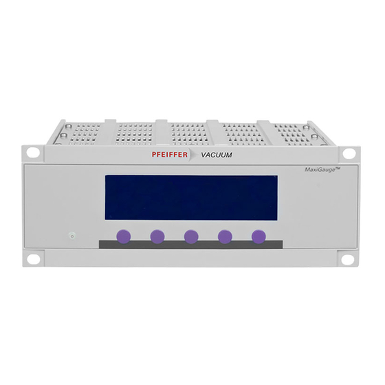
5 Operating Elements and Modes 5.1 Operating Elements Softkeys The MaxiGauge™ is operated with the five softkeys on the front panel (→ figure 14). The functions of these soft- keys vary depending on the operating mode the unit is in. The current function is indicated by the LCD graphic display. - Page 25 Figure 14: Front panel MaxiGauge MaxiGauge 1 Mains power indicator (green LED): on / off 2 Display (LCD): Measured values and operation data 3 5 Softkeys (operating keys with varying functions) Figure 15: Power switch Operating elements and modes BG 805 186 BE / B (2005-07) MaxiGauge.om...
-
Page 26: Test Mode
Figure 16: Operating modes Measurement Mode Setpoint Mode General Parameter Mode Sensor Parameter Mode Sensor Control Mode Test Mode Operating elements and modes BG 805 186 BE / B (2005-07) MaxiGauge.om... -
Page 27: Operating Modes (Overview)
5.2 Operating Modes (Overview) «Measurement» In «Measurement» mode, the MaxiGauge™ displays either the measured value of one single gauge at a time in big characters or the measured values of all gauges simultaneously in small characters (→ 28, 40). «Setpoint» In «Setpoint»... -
Page 28: Measurement» Mode
5.2.1 «Measurement» Mode Figure 17: «Single» display ³´µ ³´µ Ø´Ù ³´µ Ø´Ù offset A¡ óÅ ¸ ÆÚ Â ÆÚ cal B¢ ÆÇÈ » õÝ ×ºÕ õÝ C£ ÉÊË CH 2 Ó½¾ Û ¼½¾ ß Û mbar D¤ E¥ ª£ F¦ ª¢... - Page 29 Figure 18: «All» display CH 1 2.9E-02 mbar A¡ CH 2 244.5 mbar B¢ CH 3 1.3E-08 mbar C£ CH 4 9.9E-08 mbar degas D¤ CH 5 0.00530 mbar offset E¥ CH 6 no Sensor F¦ Sensor Sen-off Single Mode Display All measurement points (1 ...
-
Page 30: Setpoint» Mode
5.2.2 «Setpoint» Mode Figure 19: «Setpoint» display ³´µ Control Sensor 3  Setpoint high 5.00E-05 mbar  Setpoint low 2.00E-05 mbar ¼½¾ UR-Control Relay next ®¯ ¬− Return Display Switching function selected (from A ... F) Control Sensor Controlling source (1 ... 6) of switching function C (→... -
Page 31: General Parameter» Mode
5.2.3 «General Para- meter» Mode Figure 20: Key-lock Interface RS-485 «General Parameter» display Baudrate 19200 Unit mbar Address Digits Bargraph 1 Decade Screensave 5 h Default Contrast next ®¯ ¬− Return Display Key-lock Parameter input lock enabled or dis- abled (→ Unit Pressure unit (→... -
Page 32: Sensor Parameter» Mode
5.2.4 «Sensor Para- meter» Mode Figure 21: «Sensor Parameter» display ³´µ Type APR/CMR 1000 mbar óÅ Offset 157.6 mbar ÆÇÈ CAL-Factor 1.010 ÉÊË Filter standard Name CH 2 Sensor next ®¯ ¬− Return Display Measurement point selected (from 1 ... 6) Type Family of gauge ** connected / type... -
Page 33: Sensor Control» Mode
5.2.5 «Sensor Control» Mode Figure 22: «Sensor Control» display Ò´Ô Control Hotstart ñìí Power on îïð Selfcontrol Ó½¾ OFF Threshold 9.00E-5 mbar Sensor next Return Display Measurement point selected (from 1 ... 6) Control Controlling source of measure- ment point 5 (→ Measurement point 5 is activa- ted when the unit is switched on OFF Selfcontrol... -
Page 34: Test» Mode
5.2.6 «Test» Mode Figure 23: Program BG509730-I «Test» display EPROM EEPROM Interface Display WDT-Ctrl auto next Start Return Display Program Firmware version (→ 108) RAM self-test (→ 109) EPROM EPROM self-test (→ 109) EEPROM EEPROM self-test (→ 109) Display Display self-test (→... -
Page 35: Display Formats And Pressure Units
6 Display Formats and Pressure Units 6.1 Display Formats Both, exponential and floating point formats are used. The format is changed over automatically. Pressures indicated in «Pa» are displayed in exponential format only. Figure 24: ³´µ óÐ ¿À ³´µ Ò´Ô ³´µ... -
Page 36: Pressure Units
6.2 Pressure Units Whether a particular pressure unit can be displayed or not depends on the gauge used. The MaxiGauge™ al- lows the selection of a specific pressure unit only if it is possible to display the pressure in that unit over the whole measurement range. -
Page 37: Operation
7 Operation 7.1 Personnel Specialists The unit may only be operated by skilled and trained persons that fully understand the possible hazards re- lated to the corresponding application. 7.2 Switching the Unit Check that all cables and gauges have been correctly installed and that the specifications listed in the technical On and Off data have been met. - Page 38 After power ON, the unit: • automatically performs a self-test, and «MaxiGauge™» is displayed • identifies the gauges connected • activates parameters that were in effect before the last power OFF • switches to the «Measurement» mode for the meas- urement point selected before the last power OFF •...
-
Page 39: Selecting The Operating Mode
7.3 Selecting the In the superset«Measurement» mode, you can call a menu of further operating modes by pressing the [Mode] Operating Mode softkey Select the desired mode by pressing the corresponding softkey: • [Setpoint] «Setpoint» mode • [Gen-Par] «General Parameter» mode •... -
Page 40: Measurement» Mode
7.4 «Measurement» In the superset «Measurement» mode, the unit displays the measured values. If you are in another (lower) mode Mode and do not press any key for 1 minute, the unit returns automatically to the «Measurement» mode. (→ Overview «Measurement» mode 28). -
Page 41: Switching The Gauge On/Off (Sen-On/Off)
• Press the [ 7.4.2 Switching the Sen-off ] softkey to turn the selected Gauge On/Off gauge off or the [ Sen-on ] key to turn it on. Sen-on/off CAUTION Turning a gauge on or off may affect the status of the relays. -
Page 42: Setpoint» Mode
7.5 «Setpoint» Mode In «Setpoint» mode, you can assign a controlling source to a switching function and define the upper and lower thresholds. Additionally, you can select the behavior of the switching function in the event of an underrange. (→ Overview «Setpoint» mode 30). -
Page 43: Assigning Measurement Points Control Sensor
7.5.2 Assigning The upper parameter line « Control Sensor » shows which measurement point is assigned to a switching Measurement function. Points Control Sensor The corresponding measurement point has to be as- signed to each switching function individually. In «Measurement» mode, all assignments are displayed simultaneously. -
Page 44: Defining The Threshold Values (Setpoint)
7.5.3 Defining the The upper and lower thresholds are defined in the sec- ond and third parameter line. Threshold Values Setpoint Figure 35: «Setpoint» display ³´µ Control Sensor 3  Setpoint high 5.00E-05 mbar  Setpoint low 2.00E-05 mbar ¼½¾ UR-Control Relay next... - Page 45 Figure 36: Threshold values of a switching function Setpoint high Setpoint low Time Figure 37: CH 1 2.9E-02 mbar A¡ Inverse representation of the CH 2 4.16E-01 mbar B¢ C£ CH 3 1.3E-08 mbar selected switching function ( CH 4 9.9E-11 mbar D¤...
-
Page 46: Underrange Control (Ur-Control)
NOTE Logarithmic gauges: The minimum hysteresis between the upper and lower threshold is at least 10% of the lower threshold. This prevents an unstable state. If you set the upper thresh- old lower than the lower one, this minimum hysteresis is automatically applied. - Page 47 Figure 38: «Setpoint» mode display ³´µ Control Sensor 3  Setpoint high 5.00E-05 mbar  Setpoint low 2.00E-05 mbar ¼½¾ UR-Control Relay next ®¯ ¬− Return Enabling/disabling the underrange control: • Select the «Setpoint» mode (if applicable) (→ • Press the [ next ] softkey to select the «...
-
Page 48: Bg 805 186 Be / B Maxigauge.om
7.6 «General Para- In «General Parameter» mode, you can define the sys- tem parameters for all connected gauges together. meter» Mode (→ Overview «General Parameter» mode 31). Figure 39: Key-lock Interface RS-485 «General Parameter» display Baudrate 19200 Unit mbar Address Digits Bargraph 1 Decade... -
Page 49: Selecting The Pressure Unit (Unit)
7.6.2 Selecting the The unit can display the following pressure units: (milli)bar, Torr, and Pascal. Pressure Unit Unit Figure 40: Key-lock Interface RS-485 «General Parameter» display Baudrate 19200 Unit mbar Address Digits Bargraph 1 Decade Screensave 5 h Default Contrast next ®¯... -
Page 50: Display Resolution (Digits)
7.6.3 Display Resolution For observing even fine measurement value fluctuations, the display can be increased from 2 to 3 digits. The Digits measured value will thus have a finer resolution. (Only effective for logarithmic gauges.) Figure 41: Key-lock Interface RS-485 «General Parameter»... -
Page 51: Bargraph (Bargraph)
7.6.4 Bargraph The bargraph allows quick assessment of the measured value and visual observation of the measurement Bargraph changes (trend). Figure 42: Key-lock Interface RS-485 «General Parameter» display Baudrate 19200 Unit mbar Address Digits Bargraph 1 Decade Screensave 5 h Default Contrast next... -
Page 52: Restoring Default Values (Default)
7.6.5 Restoring Default This parameter allows to restore all user defined / modi- fied parameters to the factory setting. Values ( Default Figure 43: Key-lock Interface RS-485 «General Parameter» display Baudrate 19200 Unit mbar Address Digits Bargraph 1 Decade Screensave 5 h Default Contrast next... -
Page 53: Defining An Interface (Interface)
7.6.6 Defining an The serial interfaces are used for external control of the unit as well as for transfer of measured data and modi- Interface fication of parameters (→ 13). The desired interface is Interface defined with the following parameter: Figure 44: Key-lock Interface... -
Page 54: Defining The Baud Rate (Baudrate)
7.6.7 Defining the Baud This parameter allows to set the baud rate for the serial interface defined as « Interface » parameter value. Rate ( Baudrate Figure 45: Key-lock Interface RS-485 «General Parameter» display Baudrate 19200 Unit mbar Address Digits Bargraph 1 Decade Screensave 5 h... -
Page 55: Defining The Node Address (Address)
7.6.8 Defining the Node The RS485 interface allows to set up a network of max. 32 display units per interface. The node (or device) ad- Address dress can be set between 0 and 31. Address Figure 46: Key-lock Interface RS-485 «General Parameter»... -
Page 56: Screensave (Screensave)
7.6.9 Screensave In order for the life of the CFL lamp to be prolonged (half-life period approx. 20'000 hours), the backlighting Screensave of the LC display can be switched off automatically after an adjustable delay of 1 ... 99 hours while the LCD re- mains on. -
Page 57: Display Contrast (Contrast)
7.6.10 Display Contrast This parameter allows to set the contrast of the LC dis- play within a numeric range of 0 ... 20 according to your Contrast individual requirements, such as ambient conditions and viewing angle. Figure 48: Key-lock Interface RS-485 «General Parameter»... -
Page 58: Sensor Parameter» Mode
7.7 «Sensor Para- In «Sensor Parameter» mode, you can define the pa- rameters relevant for each measurement point. meter» Mode (→ Overview «Sensor Parameter» mode 32). Figure 49: «Sensor Parameter» display ³´µ Type APR/CMR 1000 mbar óÅ Offset 157.6 mbar ÆÇÈ... -
Page 59: Gauge Identification (Type)
7.7.2 Gauge Identifi- The MaxiGauge™ automatically identifies any con- nected Pfeiffer Vacuum gauges. For linear gauges, a cation ( Type measurement range is displayed additionally as pa- rameter value * behind the gauge type ** . This pa- rameter value has to be adjusted according to the con- nected gauge type. -
Page 60: Offset Function (Offset) (Zeroing)
7.7.3 Offset Function The offset function allows the zero of linear gauges to be aligned to the currently measured value (uncorrected Offset ) (zeroing) outputsignal of the gauge) within a range of -5 ... +110% of the Full Scale setting. It affects the: display switching functions (threshold value display) analog outputs of the unit... - Page 61 Procedure for the second method: • at a pressure lower than the lower limit of the mea- surement range of the gauge, activate the offset function (« ») • press the [ next ] softkey to select the previously saved offset value (at the right hand side of « »);...
- Page 62 When the offset function is activated, the stored offset value is subtracted from the currently measured value. Example: ³´µ Type APR/CMR 1000 mbar óÅ Offset 10.3 mbar ÆÇÈ CAL-Factor 1.000 ÉÊË Filter standard Name CH 2 Sensor next ®¯ ¬− Return Currently Stored...
-
Page 63: Activating The Degas Routine (Degas)
7.7.4 Activating the Contamination of the electrode system of the Compact Fullrange™ BA Gauge (PBR 260) can cause instabilities Degas Routine of the measured values. Degas The degassing routine is used for cleaning the electrode system by heating the electron collector grid to approx. 700 °C by electron bombardment. -
Page 64: Setting The Calibration Factor (Cal-Factor)
7.7.5 Setting the The calibration function allows to adjust the measured value of a gauge. It is predominantly used for correcting Calibration Factor the measured values of logarithmic gauges for gases Cal-Factor other than N and for correcting the full scale values of linear gauges. -
Page 65: Setting The Measurement Value Filter (Filter)
7.7.6 Setting the The measurement value filter allows better evaluation of unstable or faulty measurement signals. It affects the: Measurement Value Filter display Filter switching functions (threshold value display) analog outputs of the unit serial interfaces Figure 54: «Sensor Parameter» display ³´µ... - Page 66 Slow Filter Choose «slow» if the display and the switching functions should not respond to small changes in measured val- ues. As a consequence, the unit will respond more slowly to changes in measured values. Figure 56: Measurement value filter Slow Fast Filter...
-
Page 67: Defining The Measurement Point Name (Name)
7.7.7 Defining the The measurement point name is shown on the display as CH 1, CH 2 ... CH 6 (CH = channel). Measurement Point Name ( Name These 4 characters can be overwritten with any combi- nation of characters comprising letters, digits or spaces. This may be useful, for instance, for differentiating gauges in a system or for certain functional designa- tions. -
Page 68: Sensor Control» Mode
7.8 «Sensor Control» In «Sensor Control» mode, you can define how cold cathode, and FullRange™ and ionization gauges are Mode turned on/off by other gauges or control devices. (→ Overview «Sensor Control» mode 33). Gauge control When defining the control options, note that: possibilities •... - Page 69 Figure 59: Table «Sensor Control» Controlled Controlling source sensor TPR/PCR IMR / PBR 1 ... 1E-3 1 ... 1E-5 IMR/ 1 ... 1E-3 1 ... 1E-5 1E-2 ... 1E-3 1E-2 ... 1E-5 1E-2 ... 5E-10 1E-2 ... 1E-3 1E-2 ... 1E-5 1E-2 ... 5E-10 Controlled Controlling source sensor...
-
Page 70: Selecting The Controlled Gauge (Sensor)
7.8.1 Selecting the The controlled gauge to which the following parameters access is shown as a big figure on the left of the display. Controlled Gauge Sensor Figure 60: Ò´Ô Control Sensor 6 «Sensor Control» display ñìí Threshold 1.00E-05 mbar îïð... -
Page 71: Setting The «Sensor 1
7.8.3 Setting the Setting the parameters: « Sensor 1 » • Select « Control » « Sensor 1 » as controlling Control source (→ • Press the [ next ] softkey to select « ON Threshold » • Press the [ ®¯... -
Page 72: Setting The «Manual» Control
7.8.5 Setting the You can turn on the controlled gauge with the [ Sen-on softkey and turn it off with the [ Sen-off ] softkey. If a « Manual » Control corresponding setpoint has been defined, the gauge can also be turned off automatically in the event of a pres- sure rise. -
Page 73: Setting The «Hotstart» Control
7.8.6 Setting the When the unit is switched on, the controlled gauge is turned on automatically, and when the unit is switched « Hotstart » off, it is turned off, too. However, the controlled gauge Control can also turn off itself in the event of a pressure rise (Selfcontrol). -
Page 74: Status Messages
7.9 Status Messages Status messages are not to be confounded with error messages. They only indicate the system status. If status messages are displayed instead of measured values, the received measurement signal is faulty. Figure 64: CH 1 no Sensor A¡... - Page 75 >"range" Status message IKR PKR APR IMR PBR Meaning Overrange <"range" Status message IKR PKR APR IMR PBR Meaning Underrange Sensor error 1 Status message IKR PKR APR IMR PBR Meaning Measured value in the lower error range Sensor error 2 Status message IKR PKR APR IMR PBR...
-
Page 76: Error Messages
The meanings of the error messages are listed in the following table. If the problem cannot be remedied, make a note of the error message(s) and contact your nearest Pfeiffer Vacuum Service Center. Operation BG 805 186 BE / B (2005-07) - Page 77 Figure 67: Display Possible cause Remedy Error message table No display Power cable interrupted Check the power cable Mains voltage missing / Check mains too high / too low voltage Display Screensave activated Press a softkey dark (→ Lamp defective (life) Replace the lamp Operating system error Acknowledge...
- Page 78 Display Possible cause Remedy Check according Sensor error to the following examples Acknowledging error messages (→ Pirani, Pirani/Capacitance: No supply Check supply and cable Measurement ele- Maintain or ex- ment faulty change the gauge FullRange™ Gauge: No supply Check supply and cable Pirani measurement Maintain or ex-...
-
Page 79: Communication
8 Communication 8.1 Serial Interfaces Serial interfaces are used for communication between the MaxiGauge™ and a computer (HOST). A terminal can be connected for test purposes. 8.1.1 Connection Diagrams Pin assignment RS232C/422 D-Sub, 9-pin, male Serial interface port 1 Chassis 2 RXD (RS232C) 3 TXD (RS232C) 4 not connected... -
Page 80: Connection Cable
8.1.2 Connection Cable • RS232C/422 Use shielded cable only Serial interface port CAUTION Only one of the two interfaces may be connected. MaxiGauge™ C ha ssis 1 C ha ssis 2 RXD 3 TXD G ND 5 Sig na l G ND MaxiGauge™... -
Page 81: Data Transmission
8.1.3 Data Transmission The data transmission is bi-directional (master-slave). Data format 1 Start bit, 8 data bits, 1 stop bit, no parity bit, no hardware handshake Abbreviations and Symbol Meaning symbols used HOST Computer or terminal [...] Optional elements ASCII American Standard Code for Information Interchange Dec. - Page 82 Flow control After each ASCII string the HOST must wait for a con- firmation (<ACK> or <NAK>) <CR><LF> to ensure that the input buffer of the MaxiGauge™ is empty. The input buffer of the HOST must have a capacity of at least 64 bytes.
- Page 83 <ENQ> must be transmitted to request the transmission of an ASCII string. Additional strings, according to the last selected mnemonic, are read out by repetitive trans- mission of <ENQ>. If <ENQ> is received without a valid request, the error status is transmitted. HOST MaxiGauge™...
- Page 84 Error processing All messages received are verified in the MaxiGauge™. If an error is detected, a negative acknowledgment <NAK> is output. The fault condition can subsequently be read out (→ 97). HOST MaxiGauge™ Explanation Error recognition protocol Mnemonics [and parameters] HOST transmits >...
-
Page 85: Mnemonics
8.2 Mnemonics → Baud rate Baud rate Calibration factor Sensor x Calibration factor sensor x (1 ... 6) Measurement point names Measurement point names Display control Bargraph Bargraph Display control Contrast Display control contrast Display control Digits Display digits Display control Screensave Display control screensave Degas Degas... -
Page 86: Measurement Values
8.2.1 Measurement Values Sensor on / off SEN [,x,x,x,x,x,x] <CR>[<LF>] Transmit: Sensors 1 ... 6 x = 0 > No change 1 > Off 2 > On <ACK><CR><LF> Receive: <ENQ> Transmit: x,x,x,x,x,x <CR><LF> Receive: Status Sensors 1 ... 6 NOTE Not all sensor types can be switched on and off. - Page 87 Sensor control SCx [,x,x,x.xE±yy,x.xE±yy] <CR>[<LF>] Transmit: Switching off value Switching on value Switch off the controlling source of the sensor x = 0 > Sensor 1 1 > Sensor 2 2 > Sensor 3 3 > Sensor 4 4 > Sensor 5 5 >...
- Page 88 Status and pressure PRx <CR>[<LF>] Transmit: Sensor x = 1 ... 6 <ACK><CR><LF> Receive: Transmit: <ENQ> x,x.xxxEsx <CR><LF> Receive: Measurement value (always exponential format) Status x = 0 > Measurement data okay 1 > Underrange 2 > Overrange 3 > Sensor error 4 >...
-
Page 89: Display
NOTE All channel names are ASCII strings (A ... Z; 0 ... 9). Blanks (spaces) are ignored. <ACK><CR><LF> Receive: <ENQ> Transmit: xxxx,xxxx,xxxx,xxxx,xxxx,xxxx <CR><LF> Receive: Measurement point names 8.2.2 Display Unit of NOTE measurement The selected measurement unit has only an effect on the display, i.e. -
Page 90: Switching Functions
Contrast DCC [,xx] <CR>[<LF>] Transmit: Contrast x = 0 ... 20 > Contrast dark ... light (Default = 10 (med.)) <ACK><CR><LF> Receive: <ENQ> Transmit: xx <CR><LF> Receive: Contrast Screensave DCS [,xx] <CR>[<LF>] Transmit: Screensave > Screensave off (default) x = 0 >... -
Page 91: Parameters
<ACK><CR><LF> Receive: <ENQ> Transmit: x,x.xxEsx,x.xxEsx <CR><LF> Receive: Upper threshold Lower threshold Sensor (source) Set point status SPS <CR>[<LF>] Transmit: <ACK><CR><LF> Receive: Transmit: <ENQ> x,x,x,x,x,x <CR><LF> Receive: Set point A ... F x = 0 > off 1 > on Underrange control PUC [,x,x,x,x,x,x] <CR>[<LF>] Transmit: Underrange control A ... - Page 92 <ACK><CR><LF> Receive: <ENQ> Transmit: x <CR><LF> Receive: Entry lock function Filter time constants FIL [,x,x,x,x,x,x] <CR>[<LF>] Transmit: Filter time constant sensors1 ... 6 x = 0 > fast 1 > standard (default) 2 > slow <ACK><CR><LF> Receive: <ENQ> Transmit: x,x,x,x,x,x <CR><LF> Receive: Filter time constant Calibration factor...
- Page 93 Offset correction OFC [,x,x,x,x,x,x] <CR>[<LF>] Transmit: Offset correction sensors 1 ... 6 x = 0 > off (default) 1 > activated 2 > actual measurement value = offset value <ACK><CR><LF> Receive: <ENQ> Transmit: x,x,x,x,x,x <CR><LF> Receive: Offset correction Measurement range NOTE For linear gauges, the maximum pressure should be defined (full scale value).
-
Page 94: Interfaces
<ACK><CR><LF> Receive: <ENQ> Transmit: 0,0,0,x,x,x <CR><LF> Receive: Degas status Default SAV [,1] <CR>[<LF>] Transmit: Activate the factory setting <ACK><CR><LF> Receive: 8.2.5 Interfaces Interface This functions is only useful if several interfaces are connected to the unit. RSX [,x] <CR>[<LF>] Transmit: Interface x = 0 >... - Page 95 x <CR><LF> Receive: Interface Baud rate BAU [,x] <CR>[<LF>] Transmit: Baud rate x = 0 > 300 baud 1 > 1200 baud 2 > 2400 baud 3 > 4800 baud 4 > 9600 baud (default) 5 > 19200 baud NOTE As soon as the new baud rate has been entered, the report signal is transmitted at the new baud rate.
- Page 96 RS485 node address NAD xx <CR>[<LF>] Transmit: Node address of the unit x = 00 ... 31 > Node address 00 ... 31 <ACK><CR><LF> Receive: <ENQ> Transmit: xx <CR><LF> Receive: Node address of the unit NOTE Do not transmit any LINE FEEDS (<LF>) via the RS485 half duplex line for fear they could cause data collisions on the bus.
-
Page 97: Error Messages
8.2.6 Error Messages Error status ERR <CR>[<LF>] Transmit: <ACK><CR><LF> Receive: <ENQ> Transmit: xxxxx,xxxxx <CR><LF> Receive: Error status > No error xxxxx = 0 > Sensor 1: Measurement error > Sensor 2: Measurement error > Sensor 3: Measurement error > Sensor 4: Measurement error >... -
Page 98: Test Programs For Pfeiffer Vacuum Service Specialists
8.2.7 Test Programs for NOTE Pfeiffer Vacuum Some test programs take several seconds to transmit a Service Specialists report signal. Once a test program is started, the «Test» mode re- mains active until the unit is switched off. Program version PNR <CR>[<LF>]... - Page 99 Keyboard test TKB <CR>[<LF>] Transmit: <ACK><CR><LF> Receive: Transmit: <ENQ> xx <CR><LF> Receive: 1 > Bit 0 = 1 Key 1 pressed xx = 2 > Bit 1 = 1 Key 2 pressed 4 > Bit 2 = 1 Key 3 pressed 8 >...
- Page 100 EEPROM test CAUTION This test should not be continually repeated (life time of the EEPROM). TEE <CR>[<LF>] Transmit: <ACK><CR><LF> Receive: <ENQ> Transmit: xxxxx,xxxxx <CR><LF> Receive: Error status → Test A/D converter identification inputs TAI <CR>[<LF>] Transmit: <ACK><CR><LF> Receive: Transmit: <ENQ> x.xxx,x.xxx,x.xxx,x.xxx,x.xxx,x.xxx<CR><LF>...
- Page 101 Sensor identification TID <CR>[<LF>] Transmit: <ACK><CR><LF> Receive: Transmit: <ENQ> xxxxxxxxx,xxxxxxxxx, ... ,xxxxxxxxx <CR><LF> Receive: Identification sensors 1 ... 6 xxxx = TPR/PCR (Pirani Gauge or Pirani Capacitance Gauge) IKR9 (Cold cathode to 10 mbar) IKR11 (Cold cathode to 10 mbar) (FullRange™...
-
Page 102: Maintenance And Care
9 Maintenance and Care 9.1 Personnel No special skills are required for care and cleaning of the external equipment surfaces. Specialists Persons cleaning the inside of the unit with com- pressed air need to be informed on the dangers in- herent in handling compressed air. -
Page 103: Maintenance
9.3 Maintenance The unit requires no special maintenance except for the above cleaning work. For maintenance of the gauges, please consult the corresponding documents → [1] ... [15]). Maintenance and care BG 805 186 BE / B (2005-07) MaxiGauge.om... -
Page 104: Accessories And Spare Parts
10 Accessories and Spare Parts When ordering accessories and spare parts, always mention: • all information on the product nameplate • description and ordering number according to the list Sensor cables Ordering number Sensor cable for connection to compact gauge meters, complete PT 448 250 -T meters, complete... - Page 105 Other articles Ordering number Acrylic glass stand for bench top unit PT 441 483 IF 256 RS485/422 interface (retrofit set) PT 441 240 -T RI 256 Relay interface PT 441 490 -T GS 250 Compact Gauge simulator PT 583 066 -T Figure 69: Acrylic glass stand Accessories and spare parts...
-
Page 106: Decommissioning
11 Decommissioning The owner is responsible for the disposal of the unit. He shall • either return it, freight prepaid, to a Pfeiffer Vacuum Service Center • or give it to a licensed, public or private disposal company • or reuse, recycle, or dispose of it in conformance with... -
Page 107: Appendix
Appendix Validity Table Parameter Gauge logarithmic linear Measurement Mode Sen-On Sen-off Setpoint Mode Control Sensor Setpoint high Setpoint low UR-Control Sensor Parameter Mode Type (Range) Offset Degas Cal-Factor Filter Name Sensor Control Mode Control On Threshold Off Threshold Available for the hot cathode measurement range only. -
Page 108: B: Conversion Of Pressure Units
Conversion of Pressure Units µbar mbar Torr mTorr * 750×10 14.5 mbar 0.75 14.5×10 µbar 7.5×10 0.75 14.5×10 7.5×10 14.5×10 7.5×10 14.5×10 Torr 1.33×10 1.33 1.33×10 0.133 1000 19.3×10 mTorr 1.33×10 1.33×10 1.33 0.133 1.33×10 19.3×10 6.89×10 68.9 68.9×10 6890 6.89 51.7 51.7×10... - Page 109 (software) version. Its last digit stands for the index: « » or « ». This informa- tion is always useful when contacting Pfeiffer Vacuum in case of a fault. Test of the data memory. The test is run automatically («...
- Page 110 Display Test of the RAM display memory. The test is run auto- matically (« busy » is displayed). The contrast changes progressively to bright and dark twice. If the test has been successful, « passed », if not, « error »...
- Page 111 (manual) A relay function can also be tested manually (see « automatic»): • Press the [ next ] softkey to select the « » pa- rameter • Press the [ Relay ] softkey to interrupt the automatic test routine and select a particular relay by repeatedly briefly pressing the [ Relay ] softkey...
-
Page 112: D: Literature
Literature www. pfeiffer-vacuum.net Operating manual Compact Pirani Gauge TPR 261 BG 805 175 BE Pfeiffer Vacuum GmbH, D-35614 Asslar, Deutschland www. pfeiffer-vacuum.net Operating manual Compact Pirani Gauge TPR 265 BG 805 174 BE Pfeiffer Vacuum GmbH, D-35614 Asslar, Deutschland www. pfeiffer-vacuum.net... - Page 113 Operating manual Compact Cold Cathode Gauge IKR 270 BG 805 008 BE Pfeiffer Vacuum GmbH, D-35614 Asslar, Deutschland www. pfeiffer-vacuum.net Operating manual Compact FullRange™ Gauge PKR 251 BG 805 155 BE Pfeiffer Vacuum GmbH, D-35614 Asslar, Deutschland [10] www. pfeiffer-vacuum.net Operating manual Compact FullRange™...
- Page 114 [15] www. pfeiffer-vacuum.net Operating manual Compact Piezo Gauge APR 250, APR 260, APR 262, APR 265, APR 266, APR 267 BG 805 035 BE Pfeiffer Vacuum GmbH, D-35614 Asslar, Deutschland Appendix BG 805 186 BE / B (2005-07) MaxiGauge.om...
-
Page 115: Declaration Of Conformity
Berliner Strasse 43 D–35614 Asslar Deutschland Tel +49 (0) 6441 802-0 Fax +49 (0) 6441 802-202 info@pfeiffer-vacuum.de Original: German BG 805 186 BD / B (2005-07) www.pfeiffer-vacuum.net bg805186be/ b...
Need help?
Do you have a question about the TPG 256 A and is the answer not in the manual?
Questions and answers