Pfeiffer Vacuum TC 110 Operating Instructions Manual
Electronic drive unit
Hide thumbs
Also See for TC 110:
- Operating instructions manual (10 pages) ,
- Operating instructions manual (48 pages)

Related Manuals for Pfeiffer Vacuum TC 110


Summary of Contents for Pfeiffer Vacuum TC 110
- Page 1 OPERATING INSTRUCTIONS Translation of the Original TC 110 Electronic drive unit...
-
Page 2: Telegram Example
Dear Customer, Thank you for choosing a Pfeiffer Vacuum product. Your new turbopump is designed to support you by its performance, its perfect operation and without interfering your individual application. The name Pfeiffer Vacuum stands for high-quality vacuum technology, a comprehensive and complete range of top-quality products and first-class service. -
Page 3: Table Of Contents
5.2.5 Data types used Parameter set General Control commands Status requests Set value settings Additional parameter for the DCU Operation Configuring the connections with the Pfeiffer Vacuum parameter set 7.1.1 Configure digital inputs 7.1.2 Configure the digital outputs 7.1.3 Configure analog output 3/48... - Page 4 Switching on the turbopump Switching off the turbopump Operation monitoring 7.5.1 Operating mode display via LED 7.5.2 Temperature monitoring Malfunctions General Error codes Warning and error messages when operating with DCU Service solutions from Pfeiffer Vacuum Declaration of conformity 4/48...
- Page 5 List of tables List of tables Tbl. 1: Stickers on the product Tbl. 2: Abbreviations used in this document Tbl. 3: Permissible ambient conditions Tbl. 4: Data for use in safety-related applications in accordance with IEC 61508 and IEC 62061 Tbl.
- Page 6 TC 110 connection panel Fig. 2: Connection diagram for TC 110 with connection cable Fig. 3: Connection diagram for TC 110 with connection cable and accessories Fig. 4: Connection diagram for TC 110 with external wiring Fig. 5: Connection of the electronic drive unit via “X3”...
-
Page 7: About This Manual
Keep the manual for future consultation. 1.1 Validity These operating instructions are for customers of Pfeiffer Vacuum. They describe the function of the designated product and provide the most important information for safe usage of the product. The de- scriptions comply with applicable directives. All information provided in these operating instructions refer to the current development status of the product. -
Page 8: Stickers On The Product
Meaning in this document AI/AO Analog input/analog output Ampere Interrupting Capacity Direct current Display Control Unit from Pfeiffer Vacuum DI/DO Digital input/digital output Rotation speed value of a vacuum pump (frequency, in rpm or Hz) Handheld Programming Unit Electric current... -
Page 9: Safety
Safety 2 Safety 2.1 General safety instructions This document includes the following four risk levels and one information level. DANGER Imminent danger Indicates a hazardous situation which, if not avoided, will result in death or serious injury. ► Instructions on avoiding the hazardous situation WARNING Possibly imminent danger Indicates a hazardous situation which, if not avoided, could result in death or serious injury. -
Page 10: Safety Precautions
Safety DANGER Danger to life from electric shock When establishing the voltages that exceed the specified safety extra-low voltage (according to IEC 60449 and VDE 0100), the insulating measures will be destroyed. There is a danger to life from elec- tric shock at the communication interfaces. -
Page 11: Limits Of Use Of The Product
● Use of accessories or spare parts that are not listed in these instructions 2.7 Functional safety The TC 110 drive unit (electronic drive unit) executes the “Safe Limited Speed” safety function in ac- cordance with EN 61800-5-2. In the event of an excess rotation speed, the pump motor’s commutation switches off and brings the drive into a safe state. -
Page 12: Tbl. 5: Data For Use In Safety-Related Applications In Accordance With
Safety Characteristics in accordance with EN ISO 13849-1 Characteristic Performance Level Category MTTF Average Diagnostic Coverage DC Value PL d Cat. 3 high (134 a) medium (90 % - <99 %) Tbl. 5: Data for use in safety-related applications in accordance with EN ISO 13849-1 ●... -
Page 13: Product Description
ID no. 000021320. 3.2 Product features The type TC 110 electronic drive unit is a permanent component of the turbopump. The purpose of the electronic drive unit is to drive, monitor and control the entire turbopump. Feature TM 110 Connection voltage TC 24 V DC ... -
Page 14: Installation
Installation 4 Installation 4.1 Connection diagram DANGER Danger to life from electric shock Power supply packs that are not specified or are not approved will lead to severest injuries up to death. ► Make sure that the power supply pack meets the requirements for double isolation between mains input voltage and output voltage, in accordance with IEC 61010 and IEC 60950. -
Page 15: Fig. 2: Connection Diagram For Tc 110 With Connection Cable
24 VDC* (V+) Acc. A1 Acc. A1 Acc. B1 Acc. B1 RS 485 + 24 VDC* RS 485 D+ RS 485 - RS485 RS 485 D- n.c. DC in Fig. 3: Connection diagram for TC 110 with connection cable and accessories 15/48... -
Page 16: Connection "X3
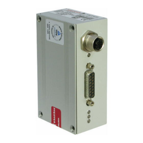
The 15-pin sub-D connection with the "X3" designation offers the possibility to operate the electronic drive unit remotely. The following specifications are the factory settings for the electronic drive unit. You can configure the settings with the Pfeiffer Vacuum parameter set. ► Use screened plugs and cables. -
Page 17: Voltage Supply
Terminal layout of the 15-pin connection "X3" 4.2.1 Voltage supply +24 V DC input/pin 1 The electrical connection to “X3” is made using connection cable from the Pfeiffer Vacuum accessory program or, by the customer, at pin 1 and pin 15. +24 V DC* output/pin 7 A connection with +24 V DC to pin 7 (active high) activates inputs 2 to 6. -
Page 18: Outputs
DCU, HPU or PC. 4.2.4 RS-485 Pin 13 and pin 14 You can connect a Pfeiffer Vacuum display and control unit (DCU or HPU) or an external PC via pin 13 and pin 14 on the D-sub connection of the electronic drive unit. 18/48... -
Page 19: Interfaces
► Connect only suitable devices to the bus system. The interface with the designation “RS-485” is intended for the connection of a Pfeiffer Vacuum display and control unit (DCU or HPU) or an external computer. The connections are galvanically safe and are isolated from the maximum supply voltage for the electronic drive unit. -
Page 20: Cross-Linked Via The Rs-485 Connection
3. Connect all devices to the bus with RS-485 D+ and RS-485 D-. 5.2 Pfeiffer Vacuum protocol for RS-485 interface 5.2.1 Telegram frame The telegram frame of the Pfeiffer Vacuum protocol contains only ASCII code characters [32; 127], the exception being the end character of the telegram C. . Basically, a master (e.g. -
Page 21: Telegram Description
● Group address "9xx" for all identical units (no response) ● global address "000" for all units on the bus (no response) Action according to telegram description n2 – n0 Pfeiffer Vacuum parameter numbers I1 – I0 Data length dn to d0 dn – d0 Data in the respective data type (see chapter “Data types used”, page... -
Page 22: Data Types Used
Interfaces Control command understood Switch on the pumping station (parameter [P:010], device address Slave: "042" --> ASCII 5.2.5 Data types used Data type Description Length l1 – l0 Example 0 – boolean_old logical value (false/true) 000000 corresponds with false 111111 corresponds with true 1 –... -
Page 23: Parameter Set
Important settings and function-related characteristics are factory-programmed into the electronic drive unit as parameters. Each parameter has a three-digit number and a description. The use of the parame- ter is possible via Pfeiffer Vacuum displays and control panels, or externally via RS-485 using Pfeiffer Vacuum protocol. - Page 24 Parameter set Display Description Functions Data Unit min. max. type cess fault type CfgSpdSwPt Configura- 0 = rotation speed switch tion rotation point 1 speed switch 1 = rotation speed switch points point 1 & 2 Cfg DO2 Configura- 0 = rotation speed switch point tion output reached 1 = no error...
- Page 25 Parameter set Display Description Functions Data Unit min. max. type cess fault type VentMode Venting 0 = delayed venting mode 1 = no venting 2 = direct venting Cfg Acc A1 Configura- 0 = fan tion accesso- 1 = venting valve, closed with- ry connec- out current tion A1...
-
Page 26: Status Requests
Parameter set Display Description Functions Data Unit min. max. type cess fault type CtrlViaInt Control via 1 = remote interface 2 = RS-485 4 = PV.can 8 = Fieldbus 16 = E74 255 = unlock interface selection IntSelLckd Interface se- 0 = off lection 1 = on... -
Page 27: Set Value Settings
Parameter set Display Description Func- Data Access Unit min. max. tions type type fault Fw version Firmware version electronic drive unit DrvVoltage Drive voltage 9999.99 OpHrsElec Operating hours electronic 65535 drive unit Nominal Spd Nominal rotation speed 999999 (Hz) DrvPower Drive power 999999 PumpCycles... -
Page 28: Additional Parameter For The Dcu
The basic parameter set is set in the electronic drive unit ex-factory. For controlling con- nected external components (e.g. vacuum measuring instruments), additional parameters (extended parameter set) are available in the corresponding Pfeiffer Vacuum display and control panels. ● Refer to the corresponding operating instructions of the respective components. - Page 29 Parameter set Display Description Functions Data Access Unit min. max. type type fault Pressure Actual pressure value 1·10 1·10 (ActiveLine) Ctr Name Display and control panel: type Ctr Software Display and control panel: software version Gauge type Type of pressure gauge Param set Parameter set 0 = Basic pa-...
-
Page 30: Operation
Operation 7 Operation 7.1 Configuring the connections with the Pfeiffer Vacuum parameter set The electronic drive unit is pre-configured with the factory default basic functions and is ready for opera- tion. For individual requirements, you can configure most connections for the electronic drive unit with the parameter set. -
Page 31: Configure Analog Output
Only for vacuum pumps with a temperature management system (TMS) The standard version of the TC 110 electronic drive unit can operate a maximum of 2 accessory outputs via connection cables. As a result, parameters [P:037] and [P:038] are without effect. -
Page 32: Select Interfaces
► Make sure that the gas mode is set correctly by [P:027] in the electronic drive unit. ► Consult Pfeiffer Vacuum before you use gases with higher molecular masses (> 80). High gas throughput and high rotation speed lead to strong friction heating of the rotor. To avoid over- heating, power to rotation speed characteristics are implemented in the electronic drive unit. -
Page 33: Set Value Power Consumption
Operation characteristic enables the operation of the turbopump at any rotation speed with the maximum permissi- ble gas throughput without thermally overloading the turbopump. The maximum power consumption de- pends on the gas type. 3 characteristics are available for the parameterization in order to completely exhaust the turbopump's capacity for each gas type. -
Page 34: Rotation Speed Switch Points
Operation 7.2.4 Rotation speed switch points You can use the rotation speed switch point for the “turbopump operational for the process” message. Exceeding or underrunning the active rotation speed switch point activates or deactivates a signal at the pre-configured output on the electronic drive unit and at the status parameter [P:302]. Rotation speed switch point 1 [P:017] = 0 f (%) -
Page 35: Rotation Speed Setting Mode
3. Check the set rotation speed (parameter [P:308] or [P:397]). 7.2.6 Standby Pfeiffer Vacuum recommends standby mode for the turbopump during process and production stops. When standby mode is active, the electronic drive unit reduces the rotation speed of the turbo pump. -
Page 36: Confirming The Rotation Speed Set Value
Fluctuations in the power consumption of idling turbopumps and varying fore-vac- uum pressures of the backing pumps require individual settings of the interval operation. Pfeiffer Vacuum recommends interval operation between 5 and 10 hPa. A pressure gauge and a dosing valve are required to set the switching thresholds. -
Page 37: Backing Pump Standby Mode
► Set the connections via the parameters [P:035], [P:036], [P:037] or [P:038]. The standard version of the TC 110 electronic drive unit can operate a maximum of 2 accessory outputs via connection cables. As a result, parameters [P:037] and [P:038] are without effect. -
Page 38: 11Venting Modes
Operation Configuring the heating Activation of the connected housing heating depends on the rotation speed switch point 1 (factory set- ting 80% x f Nominal ► Switch the heating on or off with parameter [P:001]. Configuring the fan 1. Set the selected parameter to “0” for continuous operation of the fan. 2. -
Page 39: Switching Off The Turbopump
7.5.1 Operating mode display via LED LEDs on the electronic drive unit show the basic operating states of the vacuum pump. A differentiated error and warning display is only possible for operation with the Pfeiffer Vacuum display and control unit or a PC. - Page 40 Operation ● In order to avoid switching off the turbopump, the electronic drive unit already reduces the power consumption in case of exceeding the warning threshold for excess temperature. ─ Examples are an impermissible motor temperature, or impermissibly high housing tempera- ture.
-
Page 41: Malfunctions
● Incorrect mains in- ● Check the mains input voltage put voltage ● Only acknowledge when rotation speed f = 0 ● Contact Pfeiffer Vacuum Service. ● Run-up time thresh- ● Adjust the run-up time to the process conditions Err006 Run-up error ●... - Page 42 ● Check the operating conditions ● Insufficient cooling ● Improve the cooling Err045 Excess temperature, motor ● Check the operating conditions ● Contact Pfeiffer Vacuum Service. Err046 Internal initialization error – Err091 Internal device error – ● Contact Pfeiffer Vacuum Service.
-
Page 43: Warning And Error Messages When Operating With Dcu
Invalid pump information ● Turbopump data faulty ● Establish the factory settings by ac- knowledging ● Connection to turbopump faulty ● Contact Pfeiffer Vacuum Service. Wrn098 Incomplete pump infor- mation ● Permissible specifications for ro- ● Check [P:707] or [P:717]... - Page 44 ● Replace the pressure gauge com- pletely ● external RAM faulty ● Contact Pfeiffer Vacuum Service. ** Error E040 ** Hardware error ● EPROM checksum incorrect ● Contact Pfeiffer Vacuum Service. ** Error E042 **...
-
Page 45: Service Solutions From Pfeiffer Vacuum
We are consistently striving to perfect our core competence, service for vacuum components. And our service is far from over once you’ve purchased a product from Pfeiffer Vacuum. It often enough really just begins then. In proven Pfeiffer Vacuum quality, of course. - Page 46 Service solutions from Pfeiffer Vacuum 5. Prepare the product for transport in accordance with the details in the declaration of contamination. a) Neutralize the product with nitrogen or dry air. b) Close all openings with airtight blank flanges. c) Seal the product in appropriate protective film.
-
Page 47: Declaration Of Conformity
EU Directives: ● Electromagnetic compatibility 2014/30/EU ● Low voltage 2014/35/EC ● Restriction of the use of certain hazardous substances 2011/65/EU TC 110 Harmonized standards and applied national standards and specifications: DIN EN 61000-3-2 : 2014 DIN EN 61000-3-3 : 2013...
Need help?
Do you have a question about the TC 110 and is the answer not in the manual?
Questions and answers