
Subscribe to Our Youtube Channel
Related Manuals for Bentone BF 1 FUV FAME/RME


Summary of Contents for Bentone BF 1 FUV FAME/RME
- Page 1 CR00161 178 152 35-4 2021-10–27 Providing sustainable energy solutions worldwide Installation- and maintenance instruction BF 1 FUV FAME/RME LMO14.113C2E ANV47C Translation of the original instructions.
- Page 2 1~230V 1,0A 50Hz IP 20 Motor supply MADE IN SWEDEN BY 1. Manualer på övriga språk 1. Manuals in other languages 1. Manualer på andre sprog 2. www.bentone.com\ 2. www.bentone.com\download 2. www.bentone.com\download nedladdning or scan QR-code. eller scan QR-koden. eller scanna QR-koden.
-
Page 3: Table Of Contents
9.2 Burner will not start after normal use ________________ 36 9.3 Delayed ignition __________________________________ 37 9.4 Noise in pump ___________________________________ 37 9.5 Pump pressure __________________________________ 38 10. Log of flue gas analysis ____________________________ 39 11. Oil burners maintenance instructions _______________ 40 Bentone... -
Page 4: Safety Information
• The surface temperature of the burner’s components can exceed 60 °C. • Caution: The burner has moving parts, and there is risk of crushing injuries. • The electrical installation must be professionally carried out in accordance with applicable high voltage regulations, as per Enertech’s recommendations. 165 105 85 Bentone... - Page 5 - fl ue gas ducts and combustion air ducts are not blocked - all actuators and control and safety devices are in working order and correctly set • After commissioning - If the gas burner control has a solid red light, contact your installer. Bentone...
- Page 6 Oil hoses must be of high-quality fluoride rubber or PTFE intended for FAME, B-100 (RME). The hoses must be fitted with fire-retardant sleeves in order to satisfy requirements according to EN-ISO 6806. Bentone...
- Page 7 Delivery check • Make sure everything is delivered and the goods have not been damaged during transit. • If something is wrong with a delivery, report it to the supplier. • Transport damage must be reported to the shipping company. Bentone...
-
Page 8: Technical Data
• Fuel oil A Bio 10 according to DIN 51603-6. • FAME/RME according to EN 14214. • HVO/XTL according to EN 15940. 2.1 Dimensions BF 1 FU/FUV 2.1.1 Dimensions, flanges Flange 1 Flange 2 ø89,7 ø90 130–150 125–150 165 305 50-2 Bentone... -
Page 9: Electrical Specification En 60335-2-102
Max operating current, see data plate 2.3 Model BF 1 FU/FUV 63-16 1,6–2,0 (-0,1)+0,5 7,0–8,0 Protrusion from flange, measurement B Length of flame tube Flange 1 Flange 2 2.3.1 Working area 1.3-4.6 kg/h 15-55 kW mbar Do not exceed the working area. -0,5 Bentone... - Page 10 When operating at high power or low air excess and HVO/XTL is used as fuel, the flame signal may deteriorate (blue flame), the signal lamp in the reset button flashes green. By lowering the air velocity or changing the flame detector to QRC1 A1, the flame signal can be improved. Bentone...
-
Page 11: Recommended Nozzles And Pressures
/s (cSt) at a density of 830 kg/m Burner with preheater Allow for a reduction in oil quantity of 5–20% with preheating owing to: • Temperature increases at the nozzle. • Nozzle design. • Capacity (the higher the capacity the lower the difference). Bentone... -
Page 12: Components
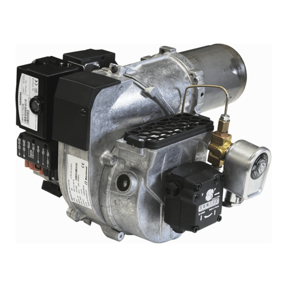
Ignition transformer Separating screw Flame tube Oil burner control Grid Solenoid valve Electrical contact X1 (refer to wiring diagram) Motor Oil pump Capacitor Air regulator Preheater, where fitted Air intake Ignition electrode Air flow indicator Ignition cable Fan housing, rear Bentone... - Page 13 Bentone...
-
Page 14: Installation
(Refer to basic settings). Note that this only refers to the basic setting; the setting must be adjusted after the burner has been started. At this time flue gas analysis and soot measurement must be carried out. 165 305 18 Bentone... -
Page 15: Burner Installation
X2 in accordance with the wiring diagram. Disconnect the power at the main switch. Wire the Eurostecker X2 as in alt. 1–3 (refer to Electrical equipment). Connect the Eurostecker X2 to the burner. Switch on the power at the main switch. Bentone... -
Page 16: Basic Settings
This provides the following nozzle according to the nozzle table, (see Technical data). Nozzle: 0.75 Gph Pump pressure: 11.0 bar Setting values for 33 kW according to basic setting diagram, (see Technical data). Air setting: 13.0 Insert setting: 165 305 19-2 Bentone... -
Page 17: Nozzle Assembly Adjustment
STD position to achieve good starts and operations. (A cast-in arrow on the fan housing indicates the position of the inlet cone. In addition to the scale on the inlet cone casting, there is also a mark (M) indicating the factory setting.) Bentone... -
Page 18: Air Intake Rotation
A hose connection air duct is available in three different dimensions: 48, 68, and 78 mm outer diameter (D). The air duct is installed on the air intake at the place where the grille is attached in the standard model Bentone... -
Page 19: Burner Servicing
When servicing or replacing components that affect combustion, analyses and soot tests must be carried out on the installation. 165 305 51 Bentone... - Page 20 Connect the Eurostecker and switch on the power at the main switch. Start the burner and check the combustion. When servicing or replacing components that affect combustion, analyses and soot tests must be carried out on the installation. Bentone...
- Page 21 Re-assemble the burner. Connect the Eurostecker and switch on the power at the main switch. Start the burner and check the combustion. When servicing or replacing components that affect combustion, analyses and soot tests must be carried out on the installation. Bentone...
- Page 22 Reassemble in reverse order. Do not forget thread sealer between the pump and the elbow. (t.ex Loctite 5188, 5400) fi g 1 When servicing or replacing components that affect combustion, analyses and soot tests must be carried out on the installation. Bentone...
- Page 23 Join together the fan housing and the burner front piece. Connect the Eurostecker and switch on the power at the main switch. Start the burner and check the combustion. When servicing or replacing components that affect combustion, analyses and soot tests must be carried out on the installation. Bentone...
- Page 24 If cleaning is not necessary, re-assemble the burner. Connect the Eurostecker and switch on the power at the main switch. Start the burner and check the combustion. When servicing or replacing components that affect combustion, analyses and soot tests must be carried out on the installation. Bentone...
- Page 25 Connect the Eurostecker and switch on the power at the main switch. Start the burner and check the combustion. When servicing or replacing components that affect combustion, analyses and soot tests must be carried out on the installation. Bentone...
- Page 26 Warning contact to earth is established between the console and the burner body. Only use electrical components recommended by Enertech. When servicing or replacing components that affect combustion, analyses and soot tests must be carried out on the installation. Bentone...
- Page 27 When replacing the electrical components transformer and control box included in the electrical package, the junction box lid need not be removed. When servicing or replacing components that affect combustion, analyses and soot tests must be carried out on the installation. Bentone...
-
Page 28: Pump Instructions
Oil temperature: max. 60°C 6.1.2 Components Nozzle connection G 1/8” Vacuum manometer connection G 1/8” Manometer connection G 1/8” Filter Suction line G 1/4” Metal plug G 1/4” Return plug Return line G 1/4” Pressure regulation 165 305 52 Bentone BF1... - Page 29 6.1.5 Two-pipe system Conversion to two-pipe system Remove the metal plug (7) G ¼”, fi t the return plug (8) in the return line (9). Return plug are not included in products with one-pipe system, separately sold. 6.1.6 Solenoid valve Bentone BF1...
- Page 30 At that same moment the nozzle line is closed. This provides a sharp cut-off. The on and off functions can be controlled independent of motor rpm, and react very quickly. When the solenoid valve is not activated torque is low up to full motor rpm. Bentone BF1...
- Page 31 The tables give the total suction line length in meters with a nozzle capacity of 2.1 kg/h. Max. permissible pressure on the suction and return lines is 2.0 bar. For a two-pipe system the Q 46 l/h pump capacity at 0 bar applies. Bentone BF1...
-
Page 32: Preheater
If the oil temperature is low and the oil flow is high, the preheater thermostat may cut out. Because of this it is important that the burner control system has a circuit that maintains preheat. 165 205 57 Bentone... -
Page 33: Oil Burner Control
8. Oil Burner Control 8.1 Wiring diagram Alt 2 Alt 3 Alt 4 Alt. 1 Enl DIN 4791 165 205 56 Bentone... -
Page 34: Function Lmo14/24
< 1 s < 1 s Ambient temperature -5 - +60°C -20 - +60°C Min detector current required (with fl ame) 45 µA dc 45 µA dc Max perm. detector current (without fl ame) 5.5 µA dc 5.5 µA dc Bentone... -
Page 35: Colour Codes Lmo14/24
If the reset button is instead kept pressed a second time for at least 3 seconds, you can, via an interface, obtain the corresponding information on a computer or flue gas analyser. To return to normal operation: Press the reset button for 1 second. Bentone... -
Page 36: Fault Location
Preheater temperature too low Check preheater function New oil type Adjust the preheater‘s set operating temperature Check that the oil used has the physical parameters that the burner is rated for. If not, change the oil. 165 105 09-2 2021-01-21 Bentone... -
Page 37: Delayed Ignition
Check that the oil used has the physical parameters that the burner is rated for. If not, change the oil. Temperature of the oil from the tank is too low, increase the temperature of oil from tank Clean the pump filter 165 105 09-2 2021-01-21/2 Bentone... -
Page 38: Pump Pressure
Pump worn Replace the pump Pump run using impure oil that has worn the Replace pump and install self-cleaning pump out prematurely filter in the oil system Blocked pump filter Check, clean pump filter 165 105 09-2 2021-01-21/3 Bentone... -
Page 39: Log Of Flue Gas Analysis
10. Log of flue gas analysis Owner Adresss Tel. no: Installation Tel. no: Boiler Type Make Power Bentone Burner Serial no. Type Model Fuel Step 1 Step 2 Step 3 Draught in fireplace Fan Press mbar Filter smoke number Flue gas temp. °C... -
Page 40: Oil Burners Maintenance Instructions
11. Oil burners maintenance instructions General information If the burner starts but does not ignite Make an attempt to start the burner. Keep the boiler room clean. Ensure that the boiler room has permanent fresh air intake. Switch off before Never make close repeated start attempts. - Page 44 Enertech AB. P.O Box 309, SE-341 26 Ljungby. www.bentone.com...
Need help?
Do you have a question about the BF 1 FUV FAME/RME and is the answer not in the manual?
Questions and answers