
Subscribe to Our Youtube Channel
Related Manuals for Bentone BF 1 FUV RME


Summary of Contents for Bentone BF 1 FUV RME
- Page 1 178 152 35-1 2019-10–24 Providing sustainable energy solutions worldwide Installation- and maintenance instruction BF 1 FUV Original translation of Installation- and maintenance instruction...
- Page 2 Beispiel Manualer på övriga språk www.bentone.com\nedladdning 352011030141 Serial no. 1234567 Man.Year 2019 Designation BF 1 KS 76-24 eller scanna QR-koden BF 1 Type BF 1 KS 76-24 Model Cap. Min-Max LIGHT OIL 35-90kW 1,25-6,0 cSt 7-14bar Skriv in brännarens artikelnummer som finns på din...
-
Page 3: Table Of Contents
___________________________________________ 5.1.2 Combustion assembly service ______________________ 5.1.3 Preheater replacement _________________________________ 5.1.4 Replacing the oil pump _______________________________ 5.1.5 Fan motor replacement ________________________________ 5.1.6 Air intake and intake cone service _________________ 5.1.7 Fan wheel checks ________________________________________ 5.1.8 Electrical module _________________________________________ Bentone BF1... -
Page 4: General Information
• Burner pipes, fan wheels and air dampers may contain sharp edges. • The surface temperature of the burner’s components can exceed 60 °C. • Caution: The burner has moving parts, and there is risk of crushing injuries. 165 105 01 Bentone BF1... - Page 5 - fl ue gas ducts and combustion air ducts are not blocked - all actuators and control and safety devices are in working order and correctly set • After commissioning, if a steady red light on the burner control is displayed, contact your installation technician. Bentone BF1...
-
Page 6: General Requirements Rme
Oil hoses must be of high-quality fluoride rubber or PTFE intended for FAME, B-100 (RME). The hoses must be fitted with fire-retardant sleeves in order to satisfy requirements according to EN-ISO 6806. Detailed ecodesign information can be downloaded at: www.bentone.com/ecodesign Bentone BF1... -
Page 7: Burner Servicing Schedule
• Make sure everything is delivered and the goods have not been damaged during transit. • If something is wrong with a delivery, report it to the supplier. • Transport damage must be reported to the shipping company. Bentone BF1... -
Page 8: Technical Data
Flange 1 Flange 2 ø89,7 ø90 130–150 125–150 2.1.2 Electric Specification Burner correspond to IP 20 Type Motor Complete Sound burner 110W 0,9A 230V 70dBA ± 0,5 230V 1,74A 50Hz 50/60Hz 4µF Max operating current, see data plate Bentone BF1... -
Page 9: Model Bf1 Fu/Fuv
Protrusion from flange, measurement B Length of blast tube Flange 2.1.1 Burner output/ Basic settings kg/h 22,0 20,0 18,0 16,0 14,0 12,0 10,0 -0,5 Burner output, kW Burner output, kW Scale value applies to 0 mbar furnace pressure. Bentone BF1... -
Page 10: Recommended Nozzles And Pressures
/s (cSt) at a density of 830 kg/m 2.3.1 Burner with preheater Allow for a reduction in oil quantity of 5–20% with preheating owing to: • Temperature increases at the nozzle. • Nozzle design. • Capacity (the higher the capacity the lower the difference). Bentone BF1... -
Page 11: Description
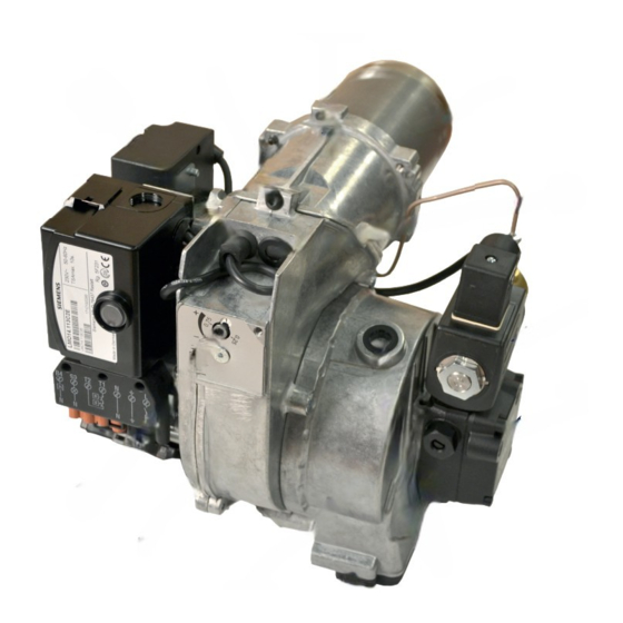
Separating screw Blast tube Grid Oil burner control Electrical contact X3 (refer to wiring diagram) Solenoid valve Motor Oil pump Capacitor Air regulator Preheater, where fitted Air intake Ignition electrode Air flow indicator Ignition cable Fan housing, rear Bentone BF1... - Page 12 General Bentone BF1...
-
Page 13: Installation
(Refer to basic settings). Note that this only refers to the basic setting; the setting must be adjusted after the burner has been started. At this time flue gas analysis and soot measurement must be carried out. Bentone BF1... -
Page 14: Burner Installation
X2 in accordance with the wiring diagram. Disconnect the power at the main switch. Wire the Eurostecker X2 as in alt. 1–3 (refer to Electrical equipment). Connect the Eurostecker X2 to the burner. Switch on the power at the main switch. Bentone BF1... -
Page 15: Basic Settings
Nozzle: 0,75 Gph Pump pressure: 9,5 bar * Calorfic value Light oil 11,86 kWh/kg 4.1.2 Basic setting Setting values for 30 kW according to basic settings tables. (Refer to Technical data FU 63-16). Air setting 11,0 Insert setting Bentone BF1... -
Page 16: Nozzle Assembly Adjustment
STD position to achieve good starts and operations. (A cast-in arrow on the fan housing indicates the position of the inlet cone. In addition to the scale on the inlet cone casting, there is also a mark (M) indicating the factory setting.) Bentone BF1... -
Page 17: Air Intake Rotation
A hose connection air duct is available in three different dimensions: 48, 68, and 78 mm outer diameter (D). The air duct is installed on the air intake at the place where the grille is attached in the standard model Bentone BF1... -
Page 18: Burner Servicing
When servicing or replacing components that affect combustion, analyses and soot tests must be carried out on the installation. Bentone BF1... -
Page 19: Combustion Assembly Service
Connect the Eurostecker and switch on the power at the main switch. Start the burner and check the combustion. When servicing or replacing components that affect combustion, analyses and soot tests must be carried out on the installation. Bentone BF1... -
Page 20: Preheater Replacement
Connect the Eurostecker and switch on the power at the main switch. Start the burner and check the combustion. When servicing or replacing components that affect combustion, analyses and soot tests must be carried out on the installation. Bentone BF1... -
Page 21: Replacing The Oil Pump
Turn the valve forward and detach it from the pump. Reassemble in reverse order. fi g 1 When servicing or replacing components that affect combustion, analyses and soot tests must be carried out on the installation. Bentone BF1... -
Page 22: Fan Motor Replacement
Connect the Eurostecker and switch on the power at the main switch. Start the burner and check the combustion. When servicing or replacing components that affect combustion, analyses and soot tests must be carried out on the installation. Bentone BF1... -
Page 23: Air Intake And Intake Cone Service
Connect the Eurostecker and switch on the power at the main switch. Start the burner and check the combustion. When servicing or replacing components that affect combustion, analyses and soot tests must be carried out on the installation. Bentone BF1... - Page 24 Connect the Eurostecker and switch on the power at the main switch. Start the burner and check the combustion. When servicing or replacing components that affect combustion, analyses and soot tests must be carried out on the installation. Bentone BF1...
-
Page 25: Electrical Module
Only use electrical components recommended by Enertech. When servicing or replacing components that affect combustion, analyses and soot tests must be carried out on the installation. Bentone BF1... - Page 26 When replacing the electrical components transformer and control box included in the electrical package, the junction box lid need not be removed. When servicing or replacing components that affect combustion, analyses and soot tests must be carried out on the installation. Bentone BF1...
-
Page 27: Pump Instructions
7–14 bar Oil temperature: max. 60°C 6.1.2 Components Nozzle connection G 1/8” Vacuum manometer connection G 1/8” Manometer connection G 1/8” Filter Suction line G 1/4” Metal plug G 1/4” Return plug Return line G 1/4” Pressure regulation Bentone BF1... -
Page 28: Filter Replacement
6.1.5 Two-pipe system Conversion to two-pipe system Remove the metal plug (7) G ¼”, fi t the return plug (8) in the return line (9). Return plug are not included in products with one-pipe system, separately sold. 6.1.6 Solenoid valve Bentone BF1... -
Page 29: Function Anv47C
At that same moment the nozzle line is closed. This provides a sharp cut-off. The on and off functions can be controlled independent of motor rpm, and react very quickly. When the solenoid valve is not activated torque is low up to full motor rpm. Bentone BF1... -
Page 30: Suction Pipe Tables Anv47C
The tables give the total suction line length in meters with a nozzle capacity of 2.1 kg/h. Max. permissible pressure on the suction and return lines is 2.0 bar. For a two-pipe system the Q 46 l/h pump capacity at 0 bar applies. Bentone BF1... -
Page 31: Preheater
If the oil temperature is low and the oil flow high, the preheater thermostat may open owing to the PTC element’s inability to maintain oil temperature. In this case it is important to use oil burner controls with a preheater holding circuit. Bentone BF1... -
Page 32: Replacement Of Electrical Components
Remove the existing component. Install the new component using the same wiring as the existing component or the specified alternative arrangement. Turn on the mains power. Check the function of the new component. Start the burner. Check combustion.* Bentone BF1... -
Page 33: Electrical Equipment Lmo1
General 9. Electrical equipment LMO1..2..4.. 9.1 Wiring diagram Bentone BF1... -
Page 34: Component List
If burner operations are interrupted via the main switch or thermostat, a new start will be initiated when conditions according to point 1 are fulfilled. Oil burner control blocks Red light on the oil burner control illuminates. The burner is re- started by pressing the reset button. Bentone BF1... -
Page 35: Technical Data
45 µA dc 45 µA dc Max current when dark, start: 5,5 µA dc 5,5 µA dc 5,5 µA dc Photocell current checks Photocell current is measured with a direct current ammeter (mulitimeter μA) connected in series with the photocell. Bentone BF1... -
Page 36: Colour Codes Lmo14/24
If the reset button is instead kept pressed a second time for at least 3 seconds, you can, via an interface, obtain the corresponding information on a computer or flue gas analyser. To return to normal operation: Press the reset button for 1 second Bentone BF1... -
Page 37: Fault Location
Check preheater function Preheater temperature too low Adjust the preheater‘s set operating tem- New oil type perature Check that the oil used has the physical parameters that the burner is rated for. If not, change the oil. 165 105 09 Bentone BF1... -
Page 38: Delayed Ignition
Change the oil or the pump's oil parameters Pump worn Replace the pump Pump run using impure oil that has worn the Replace pump and install self-cleaning pump out prematurely filter in the oil system Blocked pump filter Check, clean pump filter Bentone BF1... -
Page 39: Log Of Flue Gas Analysis
General 11. Log of flue gas analysis Owner Adresss Tel. no: Installation Tel. no: Boiler Type Make Power Bentone Burner Type Model Serial no. Fuel Step 1 Step 2 Step 3 Draught in fireplace Fan Press mbar Filter smoke number Flue gas temp. -
Page 40: Oil Burners Maintenance Instructions
If the burner will not start Press the reset button on the relay. Check that the thermostats are correctly adjusted. Don´t forget the room thermostat, check that any fusesare intact and main switch is on. Installed by: Tel: Bentone BF1... -
Page 41: Declaration Of Conformity
13. DECLARATION OF CONFORMITY... - Page 44 Enertech AB. P.O Box 309, SE-341 26 Ljungby. www.bentone.se, www.bentone.com...
Need help?
Do you have a question about the BF 1 FUV RME and is the answer not in the manual?
Questions and answers