Bentone BFG1 Installation And Maintenance Instruction
Biogas
Hide thumbs
Also See for BFG1:
- Installation and maintenance instruction (24 pages) ,
- Installation and maintenance instruction (52 pages)

Subscribe to Our Youtube Channel
Related Manuals for Bentone BFG1


Summary of Contents for Bentone BFG1
- Page 1 178 111 35-2 2018-03–06 Providing sustainable energy solutions worldwide Installation- and maintenance instruction BFG1 STG146 Biogas...
-
Page 3: Table Of Contents
Important to remember! ______________________________________________ Service _____________________________________________________________________ What to do if you smell gas _________________________________________ Safety instructions ______________________________________________________ Delivery check ____________________________________________________________ Dimensions BFG1 Biogas __________________________________________ 1.1 Description BFG1 _____________________________________________________ 1.1.1 Components BFG1 _______________________________________ Dimensions STG Biogas __________________________________________ 2.1 Description STG _____________________________________________________ 2.1.1 Components... -
Page 4: Important To Remember
• Burner pipes, fan wheels and air dampers may contain sharp edges. • The surface temperature of the burner’s components can exceed 60 °C. • Caution: The burner has moving parts, and there is risk of crushing injuries. 172 515 01 2018-01-02 Bentone... -
Page 5: Service
fl ames or sparking, e.g. do not turn lights on or off, do not use any electrical appliances, do not use mobile phones. Open windows and doors. Close the gas ball valve. Warn residents; do not use doorbells. Evacuate the building. Notify the installer or gas supplier once the building has been evacuated. Bentone... -
Page 6: Delivery Check
Delivery check • Make sure everything is delivered and the goods have not been damaged during transit. • If something is wrong with a delivery, report it to the supplier. • Transport damage must be reported to the shipping company. Bentone... -
Page 7: Dimensions Bfg1 Biogas
General 1. Dimensions BFG1 Biogas The above-mentioned measurements are maximum measurements. They can vary, depending on which components are used. Connection pressure 25 mbar 60% H -0,5... -
Page 8: Description Bfg1
General Description BFG1... -
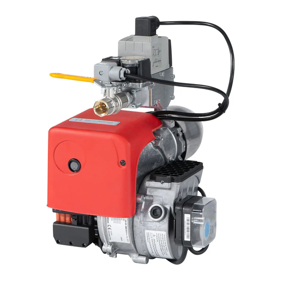
Page 9: Components Bfg1
General 1.1.1 Components BFG1 Blast tube Gas pressure switch Connection multiblock Ignition transformer Motor Capacitor Multiblock Air pressure switch Air intake Air regulation Electric connection Gas burner control Reset button Nozzle assembly adjustment Screw for division of burner in front and rear part... -
Page 10: Dimensions Stg Biogas
General 2. Dimensions STG Biogas Connection pressure 45 mbar 60% H -1,0... -
Page 11: Description Stg
General 2.1 Description STG... -
Page 12: Components
General 2.1.1 Components Blast tube Gas pressure switch Connection multiblock Ignition transformer Motor Capacitor Multiblock Air pressure switch Test point for the air pressure switch on the low-pressure side Air intake Air regulation Electric connection Gas burner control Reset button Nozzle assembly adjustment Screw for division of burner in front and rear part Nozzle assembly... -
Page 13: Multibloc
General 3. MULTIBLOC 3.1 DMV-DLE... Double solenoid valve Type DMV-D.../11 Type DMV-DLE.../11 Nominal widths Rp 1/2 - Rp 2 Electrical connection IEC 730-1 (VDE 0631 T1) Volt U n ~(AC) 230 V Valve 2 x Class A Ambient temperature -15 °C … +60 °C Family 1 + 2 + 3 Max. -
Page 14: Disassembly Of The The Multiblock
General Screw plugs 1,2,3 may also be replaced by a measuring socket G 1/8 DIN ISO 228. Concealed connecting bore for system accessories. 3.1.1 Disassembly of the the Multiblock Loosen screws A and B do not remove. Figs 1 and 2 Remove screws C and D. - Page 15 General Remove double solenoid valve between the threaded flanges. Figs 3 and After mounting, perform leakage and functional tests. Lead seal Lead seal eye 2 in 1.5 mm dia. sealing valve. Lead seal eye 3 in 1.5mm cap stand headed screw.
- Page 16 General DMV-DLE Rapid stroke adjustment V start Factory setting DMV-DLE: Rapid stroke not adjusted Unscrew the adjustment cap E from the hydraulic brake. Turn the adjustment cap and use as a tool. Turn a-clockwise = increase rapid stroke (+). Replacing hydraulic brake unit or adjustment plate Switch off firing system.
-
Page 17: Gas Pressure Regulator Type Frs
General 3.2 Gas pressure regulator Type FRS Nominal diameters Rp 3/8 - Rp 2 1/2 DN 40 - DN 150 Never close vent nozzle! Vent plug Vent nozzle 2. Pressure taps Vent plug Connection for external pulse G 1/4 screw plug ISO 228, on both sides, optional. - Page 18 General Type Order Rp / DN Dimensions Weight max. (mm) Numbe [mbar] FRS 507 070 391 Rp 3/4 G1/4 G1/4 G1/8 1,00 FRS 510 070 409 Rp 1 G1/4 G1/4 G1/8 1,20 FRS 515 058 446 Rp 1 1/2 G1/2 G1/4 G1/4 2,50...
- Page 19 General Adjustment of outlet pressure (setpoint adjustment) Factory setting: Standard spring p2 10-30 mbar Unscrew protective cap A. Adjustment (+) Setting spindle B ”Turn counter- clockwise” = Increasing outlet pressure (setpoint) Adjustment (-) Setting spindle B ”Turn clockwise” = Reducing outlet pressure (setpoint) Check setpoint Screw on protective cap A.
-
Page 20: Electric Equipment Lme
General 4. ELECTRIC EQUIPMENT LME... 4.1 Wiring diagram Alt. 2 Alt. 3 Alt. 1 Enl. DIN 4791... -
Page 21: List Of Components
General 4.1.1 List of components Main switch Gas burner control Air pressure switch Valve, leak tester, Dungs VPS504 (optional) Gas pressure switch Ionisation electrode External reset UV-detectorQRC (LME23...) Ignition Transformer Fuse Solenoid valve Lamp, operation Plug-in contact, burner Burner motor Plug-in contact, boiler Timer total operating time Plug-in contact, burner... -
Page 22: Control Program At Faults; Fault Mode Indicator Lme
General 4.2 Control program at faults; fault mode indicator LME ..4.2.1 Colour codes Table colour codes for multi-coloured signal light (LED) Status Colour codes Colours ○………………… Waiting period «tw», other waiting periods •○ •○ •○ •○ •○ • Ignition phase, ignition controlled Blinking yellow □…………………... -
Page 23: Alarm Code Table
General 4.2.1.3 Alarm code table Red blinking code Possible causes signal lamp (LED) Blinking 2 x No flame creation at End of “TSA” - defective or fouled flame monitoring - defective or fouled fuel valves - poor burner setting - defective firing device Blinking 3 x “LP”... - Page 24 General...
- Page 25 General...
- Page 26 General...
- Page 28 Enertech AB. P.O Box 309, SE-341 26 Ljungby. www.bentone.se, www.bentone.com...
Need help?
Do you have a question about the BFG1 and is the answer not in the manual?
Questions and answers