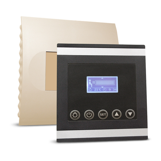
EOS InfraTec Premium Installation And Operating Instruction
Control unit for infrared cabins
Hide thumbs
Also See for InfraTec Premium:
- Installation and operating instruction (33 pages) ,
- Installation and operating instruction (45 pages)

Related Manuals for EOS InfraTec Premium


Summary of Contents for EOS InfraTec Premium
- Page 1 I N N O V A T I V E S A U N A T E C H N O L O G Y EOS InfraTec Premium Control unit for infrared cabins Installation and operating instruction Made in Germany...
-
Page 2: Table Of Contents
English Table of Contents Specifications ..............................4 Scope of delivery ............................4 General information .............................5 General safety precautions ........................5 Assembly ................................6 Relay box installation ...........................6 Control panel installation Installation ..............................7 Laying the connection cable .......................7 Electrical Connection ...........................8 Adapting the control to the installed components..............8 Installation diagram ..........................9 Terminal arrangement on the circuit board. - Page 3 Individual settings ..........................21 Room temperature ........................21 Room temperature for heating foil operation ..............22 Radiant heater for back ........................ 23 Front radiant heater ........................24 Radiant heater for legs ......................... 25 Heating time ............................ 26 Switch Off ..............................27 Error messages ............................
-
Page 4: Specifications
Specifications Voltage: 230 V 1N AC 50 Hz Fuse: 1 x 16 A Power rating: max. 3500 W Output circuits: 3 separate circuits (front, back, foot area) • Front and back individually dimmable, max. 1500 W • Switchable foot area, cannot be controlled via sensor, max. -
Page 5: General Information
The unit may only be used for its intended Dear customer, • with the purchase of this IR control unit, you have purpose as a control for IR radiant heaters. opted for a superior quality and an innovative The system must be disconnected at all poles •... -
Page 6: Assembly
Installation Relay box Wall or ceiling The relay box may only be installed outside the cabin. It is advisable to select the outside wall of the cabin or the cabin ceiling for the instal- lation. If ductwork is provided for the electri- cal installations then the position of the power switchgear is predetermined by that. -
Page 7: Installation
Installation Connection cables Control panel Insulation control panel cable The control panel should be mounted outside Inside wall of cabin Outside wall the cabin. If the control panel is mounted in- of cabin side the cabin it may not be placed in the direct range of the IR-beam and the maximum room temperature may not exceed 60°C. -
Page 8: Electrical Connection
Electrical Connection Adapting the control to the installed components. The electrical connection may only be done by a certified electrician in compliance with On the circuit board of the IR control power unit the guidelines of the local utility company you will find a pin block for three jumpers and the VDE. -
Page 9: Installation Diagram
Installation diagram IR - Emitter 1 IR - Emitter 2 IR - Emitter 3 Bedienteil Control panel = optional Leistungsteil Relay box 230 V AC 50 Hz Terminal arrangement on the circuit board. (Power unit) 0,2 AT 6,3 AT... -
Page 10: Connection Diagram For Ir Radiant Heaters
Connection diagram for IR radiant heaters NOTICE: The total power of all IR emitters in any combination may not exceed 3500 W.. -
Page 11: Connection Diagram For Ir Heating Foils
Connection diagram for IR heating foils NOTICE: The total power of all IR emitters in any combination may not exceed 3500 W.. -
Page 12: Connection Diagram For Ir Radiant Heaters And Ir Heating Foils
Connection diagram for IR radiant heaters and IR heating foils NOTICE: The total power of all IR emitters in any combination may not exceed 3500 W.. -
Page 13: Connecting The Sensor Cables
Connecting the sensor cable 2. Drill a hole to lead the cable through, prefer- ably through the middle of one of the wood- You should not draw sensor and power supply en boards. cables together or lead them through the same 3. -
Page 14: Installation Of The Optional Heating Foil Sensor
Installation of the op- • Fix the heating foil sensor cable outside the IR heating foil with the strain relief tional heating foil sensor Installation location: Strain relief The heating foil sensor shall be mounted in the area of the overheating protection of the small- Heating foil sensor est heating foil installed and shall be relaibly fixed with a strain safeguard. -
Page 15: Operation
Operation Once the system has been installed with all components and all covers have been fixed, you can put your IR cabin into operation. The following pages explain the operation, settings and options of the Infratec Premium control unit. General The user interface 28°C... -
Page 16: Default Display Stand-By
Default display Stand-by is shown if the system is in Stand-by mode. Reset to this display takes place from other menu items if no activity is carried out > 15 s. 20°C 12:00 Default display in operation is shown if the system is in operation. Reset to this display takes place from other menu items if no activity is carried out >... -
Page 17: Initial Commissioning
Initial commissioning Step 1 - connect the device to the mains To confirm press “Set” Step 2 - Select and set language > 3 sek. DE GB FR 20°C 12:00 12:00 14:35 20°C 20°C 12:00 12:00 12:00 The display shows DE GB FR the standby mode 20°C... -
Page 18: Change Language
Change language Change time 20°C 12:00 20°C 12:00 Press “Set” and ▼ Press “Set” and ▼ simultaneously simultaneously & & DE GB FR DE GB FR 20°C 12:00 12:00 20°C 12:00 12:00 Start the language Use ▼ or ▲ to jump selection mode with to the temperature “Set”... -
Page 19: Foil Temperature
Foil temperature Press “Set” for 3 sec- > 3 sec. onds to confirm If IR heating foil and the optional heating foil sensor are connected to your IR cabin, the max- imum permitted temperature for the IR heating 14:35 foil is set. 20°C 20°C 12:00... -
Page 20: Switching On The Ir System
> 3 sec. DE GB FR 20°C 12:00 12:00 To exit press „Start“ 15 sek. or wait 15 sec. The 20°C 20°C 12:00 12:00 display changes back to standby mode 15 sec. 20°C 12:00 Setting the temperature unit °C / °F 20°C 12:00 Switching on the IR system... -
Page 21: Individual Settings
Individual settings The following pages show you the options for adapting the control unit to your individual require- ments. Permanent changes of settings can only be carried out in Stand-by mode. The individual parameters can be adjusted in the same way during operation. These changes take effect immediately and are not stored permanently. -
Page 22: Room Temperature For Heating Foil Operation
Room temperature for heat- 15 s ing foil operation The display shows the temperature value to be regulated in the central area (40/55° C). 20°C 12:00 In Stand-by In operation min. 20°C 12:00 20°C 12:00 40°C 55°C 20°C 20°C 12:00 12:00 20°C 20°C... -
Page 23: Radiant Heater For Back
Back heater If the power output for IR radiators is reduced in Stand-by mode, the radiators will still heat with only possible when operating with IR 100% power up to a room temperature of 30° C. radiators Upon reaching 30° C IR radiator power output Im Stand-by will be reduced to the set value and the cabin may be heated to max. -
Page 24: Front Radiant Heater
Front side IR radiator(s) Dimmmable only by operation with IR radiators and in combination mode (IR radiators & heating foils) If the power output for IR radiators is reduced in In Stand-by Stand-by mode, the radiators will still heat with 100% power up to a room temperature of 30°... -
Page 25: Radiant Heater For Legs
IR radiator(s) for feet In Stand-by In operation min. 20°C 12:00 20°C 12:00 20°C 20°C 12:00 12:00 20°C 12:00 20°C 20°C 12:00 12:00 20°C 20°C 12:00 12:00 20°C 20°C 12:00 12:00 20°C 20°C 12:00 12:00 > 3 s 20°C 20°C 12:00 12:00 20°C... -
Page 26: Heating Time
Heating time In Stand-by In operation min. 20°C 12:00 20°C 12:00 min. min. 20°C 20°C 12:00 12:00 20°C 20°C 12:00 12:00 min. min. 20°C 20°C 12:00 12:00 20°C 20°C 12:00 12:00 5 sek. min. min. 20°C 20°C 12:00 12:00 20°C 12:00 >... -
Page 27: Switch Off
The device „Switch-off“ switch Switch-off The control unit is equipped with a “Switch-off” rocker switch. This switch allows to switch the control unit to the standby mode (notice the heating will not start), to switch the control unit completely off (disconnect from power) or to switch the con- trol unit off but to leave the light switched on. -
Page 28: Error Messages
Error messages The control unit continuously monitors the temperature sensor for short circuits and interruptions. However only the sensors which are activated are monitored. That means: If only IR radiators are connected then only the cabin temperature sensor is monitored: If only IR heating foils are connected then both sensors are monitored. -
Page 29: Recycling
2012/19/EU. Do not dispose it with the normal household waste. Service Address: EOS Saunatechnik GmbH Schneiderstriesch 1 35759 Driedorf, Germany Tel: +49 (0)2775 82-514 Fax: +49 (0)2775 82-431 servicecenter@eos-sauna.de... -
Page 30: General Terms And Conditions Of Service
The manufacturers General Terms and Conditions of Business, which can be found at www.eos-sauna.com/ V. Liability agb, shall apply in addition to the foregoing terms and conditions of service.
Need help?
Do you have a question about the InfraTec Premium and is the answer not in the manual?
Questions and answers