EOS InfraTec Premium Installation And Operating Instruction
Hide thumbs
Also See for InfraTec Premium:
- Installation and operating instruction (30 pages) ,
- Installation and operating instruction (45 pages)

Related Manuals for EOS InfraTec Premium


Summary of Contents for EOS InfraTec Premium
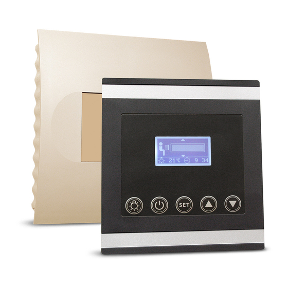
- Page 1 InfraTec Premium min. 20°C 12:00 Installation and operating instruction Made in Germany Druck Nr. 29344518 en/ -10.14...
-
Page 2: Table Of Contents
English Table of Contents Specifications ..............................4 Scope of delivery ............................4 General information .............................5 General safety precautions ........................5 Assembly ................................6 Relay box installation ...........................6 Control panel installation Installation ..............................7 Laying the connection cable .......................7 Electrical Connection ...........................8 Adapting the control to the installed components..............8 Installation diagram ..........................9 Terminal arrangement on the circuit board. - Page 3 Individual settings ..........................20 Room temperature ........................21 Room temperature for heating foil operation ..............22 Radiant heater for back ........................ 24 Front radiant heater ........................26 Radiant heater for legs ......................... 28 Heating time ............................ 29 Switch Off ..............................30 Error messages ............................
-
Page 4: Specifications
Specifications Voltage: 230 V 1N AC 50 Hz Fuse: 1 x 16 A Power rating: max. 3500 W Output circuits: 3 (2 circuits individually dimmable) Temperature control range: 30 - 70° C Control characteristics: Digital output control (channels 1 and 2) Sensor system: KTY sensor (main sensor, cabin temperature) KTY sensor (heating foil sensor, optional) -
Page 5: General Information
The unit may only be used for its intended Dear customer, • with the purchase of this IR control unit, you have purpose as a control for IR radiant heaters. opted for a superior quality and an innovative The system must be disconnected at all poles •... -
Page 6: Assembly
Installation Wall or ceiling Relay box The relay box may only be installed outside the cabin. It is advisable to select the outside wall of the cabin or the cabin ceiling for the instal- lation. If ductwork is provided for the electri- cal installations then the position of the power 19 cm switchgear is predetermined by that. -
Page 7: Installation
Installation Connection cables Control panel Insulation control panel cable The control panel should be mounted outside Inside wall of cabin Outside wall the cabin. If the control panel is mounted in- of cabin side the cabin it may not be placed in the direct range of the IR-beam and the maximum room temperature may not exceed 60°C. -
Page 8: Electrical Connection
Electrical Connection Adapting the control to the installed components. The electrical connection may only be done by a certified electrician in compliance with On the circuit board of the IR control power unit the guidelines of the local utility company you will find a pin block for three jumpers and the VDE. -
Page 9: Installation Diagram
Installation diagram IR - Emitter 1 IR - Emitter 2 IR - Emitter 3 InfraTec Premium control Terminal = optional InfraTec Premium 230 V AC 50 Hz Terminal arrangement on the circuit board. (Power unit) 0,2 AT Jumper 10 AT... -
Page 10: Connection Diagram For Ir Radiant Heaters
Connection diagram for IR radiant heaters... -
Page 11: Connection Diagram For Ir Heating Foils
Connection diagram for IR heating foils... -
Page 12: Connection Diagram For Ir Radiant Heaters And Ir Heating Foils
Connection diagram for IR radiant heaters and IR heating foils... -
Page 13: Connecting The Sensor Cables
Connecting the sensor cable 2. Drill a hole to lead the cable through, prefer- ably through the middle of one of the wood- You should not draw sensor and power supply en boards. cables together or lead them through the same 3. -
Page 14: Installation Of The Optional Heating Foil Sensor
Installation of the op- • Fix the heating foil sensor cable outside the IR heating foil with the strain relief tional heating foil sensor Installation location: Strain relief The heating foil sensor shall be mounted in the area of the overheating protection of the small- Heating foil sensor est heating foil installed and shall be relaibly fixed with a strain safeguard. -
Page 15: Operation
Operation Once the system has been installed with all components and all covers have been fixed, you can put your IR cabin into operation. The following pages explain the operation, settings and options of the Infratec Premium control unit. General The user interface 28°C... -
Page 16: Default Display Stand-By
Default display Stand-by is shown if the system is in Stand-by mode. Reset to this display takes place from other menu items if no activity is carried out > 15 s. 20°C 12:00 Default display in operation is shown if the system is in operation. Reset to this display takes place from other menu items if no activity is carried out >... -
Page 17: Initial Commissioning
Initial commissioning > 3 s DE GB FR 20°C 12:00 12:00 14:35 20°C 20°C 12:00 12:00 12:00 DE GB FR 20°C 12:00 12:00 20°C 12:00 10:00 20°C 20°C 12:00 12:00 12:00 14:00 20°C 20°C 12:00 12:00 12:00 14:00 20°C 20°C 12:00 12:00 12:00... -
Page 18: Change Language
Change language Change time 20°C 12:00 20°C 12:00 & & DE GB FR DE GB FR 20°C 12:00 12:00 20°C 12:00 12:00 10:00 DE GB FR 20°C 12:00 12:00 20°C 20°C 12:00 12:00 12:00 10:00 DE GB FR 20°C 12:00 12:00 20°C 20°C... -
Page 19: Foil Temperature
Foil temperature > 3 s If IR heating foil and the optional heating foil sensor are connected to your IR cabin, the max- imum permitted temperature for the IR heating 14:35 foil is set. 20°C 20°C 12:00 12:00 12:00 DE GB FR 20°C 12:00 20°C... -
Page 20: Switching On The Ir System
Switching on the IR system DE GB FR 20°C 12:00 12:00 20°C 12:00 15 s 20°C 12:00 min. 20°C 12:00 Switching off the IR system min. 20°C 12:00 20 minutes 20°C 12:00 Individual settings The following pages show you the options for adapting the control unit to your individual require- ments. -
Page 21: Room Temperature
Room temperature In operation In Stand-by min. 20°C 12:00 20°C 12:00 40°C 55°C 20°C 20°C 12:00 12:00 20°C 20°C 12:00 12:00 40°C 55°C 20°C 20°C 12:00 12:00 20°C 20°C 12:00 12:00 55°C 40°C 20°C 20°C 12:00 12:00 20°C 20°C 12:00 12:00 >... -
Page 22: Room Temperature For Heating Foil Operation
Room temperature for heating foil operation The display shows the temperature value to be regulated in the central area (40/55° C). In Stand-by 55°C 20°C 12:00 20°C 12:00 15 s 40°C 20°C 12:00 20°C 20°C 12:00 12:00 40°C 20°C 20°C 12:00 12:00 55°C... - Page 23 In operation min. 20°C 12:00 55°C 20°C 20°C 12:00 12:00 55°C 20°C 20°C 12:00 12:00 40°C 20°C 20°C 12:00 12:00 40°C 20°C 20°C 12:00 12:00 15 sek. min. 20°C 12:00...
-
Page 24: Radiant Heater For Back
Rear side IR radiators Only possible when operated with IR radiators. In Stand-by 20°C 12:00 20°C 20°C 12:00 12:00 15 s 20°C 20°C 12:00 12:00 20°C 12:00 20°C 20°C 12:00 12:00 20°C 20°C 12:00 12:00 > 3 s 20°C 20°C 12:00 12:00... - Page 25 In operation min. 20°C 12:00 20°C 12:00 20°C 20°C 12:00 12:00 20°C 20°C 12:00 12:00 20°C 12:00 15 sek. min. 12:00 20°C...
-
Page 26: Front Radiant Heater
Front side IR radiator(s) Dimmmable only by operation with IR radiators and in combination mode (IR radiators & heating foils) In Stand-by 20°C 20°C 12:00 12:00 20°C 12:00 15 s 20°C 12:00 20°C 20°C 12:00 12:00 20°C 20°C 12:00 12:00 20°C 20°C 12:00... - Page 27 In operation min. 20°C 12:00 20°C 12:00 20°C 20°C 12:00 12:00 20°C 20°C 12:00 12:00 20°C 12:00 15 sek. min. 20°C 12:00...
-
Page 28: Radiant Heater For Legs
IR radiator(s) for feet In Stand-by In operation min. 20°C 12:00 20°C 12:00 20°C 20°C 12:00 12:00 20°C 12:00 20°C 20°C 12:00 12:00 20°C 20°C 12:00 12:00 20°C 20°C 12:00 12:00 20°C 20°C 12:00 12:00 > 3 s 20°C 20°C 12:00 12:00 20°C... -
Page 29: Heating Time
Heating time In Stand-by In operation min. 20°C 12:00 20°C 12:00 min. min. 20°C 20°C 12:00 12:00 20°C 20°C 12:00 12:00 min. min. 20°C 20°C 12:00 12:00 20°C 20°C 12:00 12:00 min. min. 20°C 20°C 12:00 12:00 20°C 12:00 > 3 s min. -
Page 30: Switch Off
The Switch-off Switch-off You will find the rocker switch on the top side unit is turned on of the control unit relay box. You can complete- ly disconnect the control unit from the mains using this switch. Push the switch on the left side of the rocker unit is turned off to the first latch (switch setting 0). -
Page 31: Error Messages
Error messages The control unit continuously monitors the temperature sensor for short circuits and interruptions. However only the sensors which are activated are monitored. That means: If only IR radiators are connected then only the cabin temperature sensor is monitored: If only IR heating foils are connected then both sensors are monitored. -
Page 32: Service Address
Outside of Germany please contact your spe- cialist dealer in case of warranty claims. Direct Service Address: warranty processing with our service depart- ment is in this case not possible. EOS Saunatechnik GmbH Schneiderstriesch 1 Equipment commissioning date: 35759 Driedorf, Germany Tel: +49 (0)2775 82-514... -
Page 33: General Terms And Conditions Of Service
Handling procedures for return shipments (RMA) - Details for all returns ! Dear customer we hope that you will be satisfied with the purchased EOS product. In the rear case if you may have a claim and will need to return a product, please follow the procedures specified below.
Need help?
Do you have a question about the InfraTec Premium and is the answer not in the manual?
Questions and answers