
Related Manuals for Advantech AIMB-276


Summary of Contents for Advantech AIMB-276
- Page 1 User Manual AIMB-276 Intel® Core™ i7/i5/i3 LGA1151 Mini-ITX with HDMI2.0a/Dual DP++/LVDS(or eDP), 2 x COM, Dual LAN, SATAIII, 6 x USB3.1 & 4 x USB3.0, M.2 (B-key & E-key)
- Page 2 The documentation and the software included with this product are copyrighted 2019 by Advantech Co., Ltd. All rights are reserved. Advantech Co., Ltd. reserves the right to make improvements in the products described in this manual at any time without notice.
- Page 3 Advantech has come to be known. Your satisfaction is our primary concern. Here is a guide to Advantech’s cus- tomer services.
- Page 4 Caution! There is a danger of a new battery exploding if it is incorrectly installed. Do not attempt to recharge, force open, or heat the battery. Replace the battery only with the same or equivalent type recommended by the man- ufacturer. Discard used batteries according to the manufacturer's instructions. AIMB-276 User Manual...
- Page 5 Advantech SD4U8GN2 K4A4G08 SD4U8GN21-SG 1-SG H5AN8G8 SQR-SD4N- SQR-SD4N- DDR4 2400 Advantech NAFR 8G2K4HBC 8G2K4HBC UHC 643V H5AN8G8 SQR-SD4N- SQR-SD4N- DDR4 2400 16GB Advantech NAFR 16G2K4HBC 16G2K4HBC UHC 643V AQD- H5AN8G8 AQD-SD4U16N24- DDR4 2400 16GB Advantech SD4U16N24 NAFR AIMB-276 User Manual...
- Page 6 Because of Advantech’s high quality-control standards and rigorous testing, most of our customers never need to use our repair service. If an Advantech product is defec- tive, it will be repaired or replaced at no charge during the warranty period. For out- of-warranty repairs, you will be billed according to the cost of replacement materials, service time and freight.
- Page 7 It should be free of marks and scratches and in perfect working order upon receipt. As you unpack the AIMB-276, check it for signs of ship- ping damage. (For example, damaged box, scratches, dents, etc.) If it is damaged or it fails to meet the specifications, notify our service department or your local sales representative immediately.
- Page 8 AIMB-276 User Manual viii...
-
Page 9: Table Of Contents
Figure 1.1 Jumper and Connector Location (Top Side)....9 Figure 1.2 Jumper and Connector Location (Bottom Side) ..10 AIMB-276 Board Diagram ............... 11 Figure 1.3 AIMB-276 Board Diagram ........11 Safety Precautions .................. 12 Jumper Settings ..................12 1.8.1 How to Set Jumpers.............. - Page 10 Software Utility................74 Chapter Chipset Software Installation Utility Before You Begin..................76 Introduction ..................... 76 Windows 10 Driver Setup ............... 77 Chapter VGA Setup ......... 79 Introduction ..................... 80 Windows 10 .................... 80 Chapter LAN Configuration ......81 AIMB-276 User Manual...
- Page 11 A.38 Serial ATA interface power connector (SATA_PWR1/2) ...... 105 A.39 AT/ATX Mode selection (PSON1)............106 A.40 ATX supported 3-pin header on board (ATX_5VSB1) ......106 A.41 NGFF M.2 E-Key connector for 2230 module (M2E1 ) ......107 AIMB-276 User Manual...
- Page 12 AIMB-276 User Manual...
-
Page 13: Chapter 1 General Information
Chapter General Information... -
Page 14: Introduction
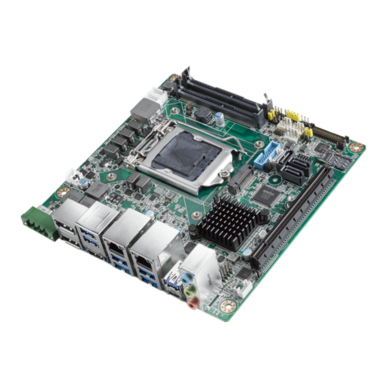
Introduction AIMB-276 is designed with the Intel® Q370 PCH for industrial applications that require both performance computing and enhanced power management capabilities. The motherboard supports Intel desktop Corei7/i5/i3/Pentium/Celeron processor up to 12 MB L3 cache and 2 DDR4 2666MHz SO-DIMM, up to 32 GB. A rich I/O connec- tivity of 2 serial ports, 10 USB, dual GbE LAN, 3 SATA, 2 NGFF (M.2_B Key &... -
Page 15: Graphics
Storage temperature: -40 ~ 85° C (-40 ~ 185° F) Humidity: 5 ~ 95% non-condensing Power supply voltage: 12~24V DC Input Board size: 170 mm x 170 mm (6.69" x 6.69") Board weight: 0.365 kg AIMB-276 User Manual... -
Page 16: Jumpers And Connectors
Jumpers and Connectors Connectors on the AIMB-276 motherboard link it to external devices such as hard disk drives and a keyboard. In addition, the board has a number of jumpers used to configure your system for your application. The tables below list the function of each of the board jumpers and connectors. Later sections in this chapter give instructions on setting jumpers. - Page 17 IC/Internal Buzzer / External Speaker header Watchdog timer output and OBS beep JWDT1+JOBS1 AT / ATX Mode selection PSON1 Case open selection pin header JCASEOP_SW1 COM1_RI# Pin selection pin header JSETCOM1_V1 LVDS VESA, JEIDA format selection pin header JLVDS_VCON1 AIMB-276 User Manual...
- Page 18 Jumper position for +12V CMOS clear (JCMOS1) Function Jumper Setting Keep CMOS Data (Default) Clear CMOS Data PWRBTN#/ RESET#/HDD LED/ Serial bus from HW monitor IC/Internal Buzzer / External Speaker header (JFP1) Function Jumper Setting Internal Buzzer (Default) AIMB-276 User Manual...
- Page 19 Jumper Setting Watchdog Timer Output (2-3) (Default) OBS BEEP(4-5) (Default) AT / ATX Mode selection (PSON1) Function Jumper Setting ATX Mode (Default) AT Mode Case open selection pin header (JCASEOP_SW1) Function Jumper Setting Normal Close Normal Open (Default) AIMB-276 User Manual...
- Page 20 COM1_RI# Pin RI# / 5V / 12V selection (JSETCOM1_V1) Function Jumper Setting Jumper position for RI# (Default) Jumper position for +5V Jumper position for +12V LVDS VESA, JEIDA format selection pin header (JLVDS_VCON1) Function Jumper Setting JEIDA mode (HI=+3.3V) VESA mode (Low=0V) (Default) AIMB-276 User Manual...
-
Page 21: Board Layout: Jumper And Connector Locations
41. SPI_CN1 8.LAN2 25. INV1 42. SATA_PWR1/2 9.USB6 26. COM1 43. PSON1 10.USB5 27. LPC1 44. ATX_5VSB1 11.AUSIO1 28. SIM1 12.AMP1 29. JLVDS_CON1 13.FPAUD1 30. LVDS_EDP1 14.JCOMS1 31. JLVDS1 15.PCIEX16_1 32. SYSFAN1/2 16.PCH1 33. JFP2 17.BAT1 34. JWDT1+JOBS1 AIMB-276 User Manual... - Page 22 [45] Figure 1.2 Jumper and Connector Location (Bottom Side) 45. M2E1 AIMB-276 User Manual...
-
Page 23: Aimb-276 Board Diagram
AIMB-276 Board Diagram Figure 1.3 AIMB-276 Board Diagram AIMB-276 User Manual... -
Page 24: Safety Precautions
1, 2, and 3. In this case you connect either pins 1 and 2, or 2 and 3. A pair of needle-nose pliers may be useful when set- ting jumpers. AIMB-276 User Manual... -
Page 25: Cmos Clear (Cmos1)
1.8.2 CMOS Clear (CMOS1) The AIMB-276 motherboard contains a jumper that can erase CMOS data and reset the system BIOS information. Normally this jumper should be set with pins 1-2 closed. If you want to reset the CMOS data, set CMOS1 to 2-3 closed for just a few seconds, and then move the jumper back to 1-2 closed. -
Page 26: Watchdog Timer Output And Obs Beep (Jwdt1+Jobs1)
(2 and 3)+(4 and 5) Watchdog Timer Disable (1-2) OBS BEEP(4-5) (Default) (1 and 2)+(4 and 5) 1.8.6 ATX/AT Mode Selection (PSON1) Table 1.7: ATX/AT Mode Selection (PSON1) Function Jumper Setting AT Mode 1-2 closed ATX Mode (Default) 2-3 closed AIMB-276 User Manual... -
Page 27: Lvds Panel Voltage Selection (Jlvds1)
5 and 6 System Memory AIMB-276 has two sockets for a 260 pins DDR4 SO-DIMM. This socket uses a 1.2 V unbuffered double data rate synchronous DRAM (DDR SDRAM). DRAM is available in capacities of 4GB, 8GB and 16GB. The sockets can be filled in any combination with SODIMMs of any size, giving a total memory size between 4GB, 8GB, 16GB, and up to max 32GB. -
Page 28: Memory Installation Procedures
1.11 Cache Memory The AIMB-276 supports a CPU with one of the following built-in full speed Last Level Cache: 8MB for Intel Core i7-6700 / i7-6700TE 6MB for Intel Core i5-6500 / i5-6500TE... -
Page 29: Chapter 2 Connecting Peripherals
Chapter Connecting Peripherals... -
Page 30: Introduction
USB Ports (LAN1_USB12/LAN2_USB34/USB56/ USB78/USB910) The AIMB-276 provides up to ten USB ports. Eight USB3.1 on the rear side and two pin header on the board. The USB interface complies with USB Specification Rev. 3.1 supporting transmission rates up to 10 Gbps. The USB interface can be disabled in the system BIOS setup. -
Page 31: Displayport1/2 (Dp12) / High-Definition Multimedia Interface Connector (Hdmi1)
1000 Mbps (On); Color: Green (1000 Mbps) DisplayPort1/2 (DP12) / High-Definition Multimedia Interface connector (HDMI1) The AIMB-276 includes two DP and one HDMI connector, which can support DP and HDMI outputs. Pin assignments for DP & HDMI are detailed in Appendix B. AIMB-276 User Manual... -
Page 32: Serial Ports (Com1~Com2)
Serial Ports (COM1~COM2) AIMB-276 supports two serial ports, COM1 supports RS-232 function, COM2 sup- ports RS-232/422/485 function by BIOS selection. These ports can connect to serial devices, such as a mouse or a printer, or to a communications network. The IRQ and address ranges for both ports are fixed. -
Page 33: Cpu Fan Connector (Cpu_Fan1)
CPU Fan Connector (CPU_FAN1) If a fan is used, this connector supports cooling fans of 500 mA (6 W) or less. AIMB-276 User Manual... -
Page 34: System Fan Connector (Sysfan1/2)
System FAN Connector (SYSFAN1/2) If a fan is used, this connector supports cooling fans of 500 mA (6 W) or less. AIMB-276 User Manual... -
Page 35: Power Switch/Hdd Led/Smbus/Speaker Pin Header (Jfp1) & Power
External speaker (JFP1/SPEAKER) JFP1/SPEAKER is a 4-pin connector for an external speaker. If there is no external speaker, the AIMB-276 provides an onboard buzzer as an alternative. To enable the buzzer, set pins 7 & 10 as closed. AIMB-276 User Manual... -
Page 36: Dc Input Phoenix Connector (Dcin1)
DC Input Phoenix Connector (DCIN1) AIMB-276 User Manual... -
Page 37: Sata Signal & Power Connector (Sata1~Sata3 / Sata_Pwr1~2)
SATA Signal & Power Connector (SATA1~SATA3 / SATA_PWR1~2) AIMB-276 features a high performance Serial ATA III interface (up to 600 MB/s) which eases hard drive cabling with thin, space-saving cables. AIMB-276 User Manual... -
Page 38: Hd Analog Audio Interface (Audio1, Fpaud1)
Connect this connector with the front panel audio I/O module cable. Note! For motherboards with the optional HD Audio feature, we recommend that you connect a high-definition front panel audio module to this con- nector to take advantage of the motherboard's high definition audio capability. AIMB-276 User Manual... -
Page 39: Pci-E X16 Slot (Pciex16_1)
2.11 PCI-E x16 Slot (PCIEX16_1) AIMB-276 provides 1 x PCI express x16 slot. AIMB-276 User Manual... -
Page 40: Low-Voltage Differential Signaling Interface/Embedded Display Port (Lvds_Edp1)
2.12 Low-voltage differential signaling interface/ Embedded display port (LVDS_EDP1) AIMB-276 User Manual... -
Page 41: Lvds Backlight Inverter Power Connector (Inv1)
2.13 LVDS Backlight Inverter Power Connector (INV1) Note! Signal Description Signal Signal Description Vadj=0.75 V (Recommended:4.7 k Ω>1/16 W ) ENBKL LCD backlight ON/OFF control signal AIMB-276 User Manual... -
Page 42: Ngff M.2 B-Key & E-Key Connector (M2B1 & M2E1)
2.14 NGFF M.2 B-Key & E-Key connector (M2B1 & M2E1) AIMB-276 User Manual... - Page 43 AIMB-276 User Manual...
-
Page 44: Audio Amplifier Output Connector (Amp1), Bom Optional
2.15 Audio Amplifier Output Connector (AMP1), BOM optional AIMB-276 User Manual... -
Page 45: General Purpose I/O Pin Header (Gpio1)
2.16 General Purpose I/O Pin Header (GPIO1) AIMB-276 User Manual... -
Page 46: Spi Bios Flash Socket (Spi1)
2.17 SPI BIOS Flash Socket (SPI1) AIMB-276 User Manual... -
Page 47: Spi Programming Pin Header (Spi_Cn1)
2.18 SPI Programming Pin Header (SPI_CN1) AIMB-276 User Manual... -
Page 48: Low Pin Count Header (Lpc1)
2.19 Low Pin Count Header (LPC1) AIMB-276 User Manual... -
Page 49: Case-Open Detect Connector (Jcase1)
2.20 Case-Open Detect Connector (JCASE1) AIMB-276 User Manual... -
Page 50: Cmos Battery Connector (Bat1)
2.21 CMOS battery connector (BAT1) AIMB-276 User Manual... -
Page 51: Cpu Socket (Cpu1)
2.22 CPU Socket (CPU1) AIMB-276 User Manual... -
Page 52: Ddr4 So-Dimm Socket (Dimma1, Dimmb1)
2.23 DDR4 SO-DIMM Socket (DIMMA1, DIMMB1) AIMB-276 User Manual... -
Page 53: Bios Operation
Chapter BIOS Operation... -
Page 54: Introduction
AIMB-276 setup screens. BIOS Setup The AIMB-276 Series system has AMI BIOS built in, with a CMOS SETUP utility that allows users to configure required settings or to activate certain system features.The CMOS SETUP saves the configuration in the CMOS RAM of the motherboard. When the power is turned off, the battery on the board supplies the necessary power to pre- serve the CMOS RAM.When the power is turned on, press the <Del>... -
Page 55: Main Menu
3.2.2 Advanced BIOS Features Select the Advanced tab from the AIMB-276 setup screen to enter the Advanced BIOS Setup screen. You can select any of the items in the left frame of the screen, such as CPU Configuration, to go to the sub menu for that item. You can display an Advanced BIOS Setup option by highlighting it using the <Arrow>... - Page 56 To enable/disable TPM (TPM 1.2/2.0) set up in BIOS. TPM (Trusted Platform Mod- ule) is a secure key generator and key cache management component, enables pro- tected storage of encryption keys and authentication credentials for enhanced security capabilities. AIMB-276 User Manual...
- Page 57 Select ACPI sleep state the system will enter when the SUSPEND button is pressed. Lock Legacy Resources [ Disabled ] Enables or Disables Lock of Legacy Resources. S3 Video Repost [ Disabled ] Enable or Disable S3 Video Repost. AIMB-276 User Manual...
- Page 58 3.2.2.3 PCH Configuration Firmware update Configuration – ME FW Image Re-Flash [ Disabled ] AIMB-276 User Manual...
- Page 59 3.2.2.4 AMT Configuration ASF support [ Enabled ] Enable/Disable Alert Specification Format USB Provisioning of AMT [Disabled] CIRA Configuration – Active Remote Assistance Process [ Disabled ] Trigger CIRA boot. AIMB-276 User Manual...
- Page 60 BIOS Timer [ 0] Set BIOS watchdog timer. Secure Erase Configuration OEM Flags Settings MEBx Resolution Settings 3.2.2.5 NCT6776 Super IO Configuration Super IO Chip [ NCT6776 ] Serial Port 1 Configuration AIMB-276 User Manual...
- Page 61 Serial Port [ Enabled ] – Device Settings: IO=3F8h; IRQ =4 – Change Settings [ Auto ] To select an optimal setting for serial port 1. Serial Port 2 Configuration AIMB-276 User Manual...
- Page 62 Serial Port [ Enabled ] – Device Settings: IO=2F8h; IRQ =3 – Change Setting [ Auto ] To select an optimal setting for serial port 2. Digital I/O Configuration Digital I/O Pin 1 - 8 [ Input ] AIMB-276 User Manual...
- Page 63 ACPI Shutdown Temperature [ Disabled ] Use this to set the ACPI shutdown temperature threshold. When the system- reaches the shutdown temperature, it will be automatically shut down by ACPI OS to protect the system from overheating damage. AIMB-276 User Manual...
- Page 64 CPU FAN Mode [ SMART FAN IV Mode ] The item shows you CPU temperature and fan speed (PWM) information. SYSFAN Mode [ SMART FAN IV Mode ] The item shows you system temperature and fan speed (PWM) information. AIMB-276 User Manual...
- Page 65 S5 RTC Wake Settings The item allow you enable or disable system wake up on alarm event. Wake system with Fixed Time [ Disabled ] Note! When enabled, system will wake up on the specified time. AIMB-276 User Manual...
- Page 66 3.2.2.8 Serial Port Console Redirection Console Redirection [ Enabled ] Enable or disable the console redirection feature 3.2.2.9 Network Stack Configuration [Disabled] AIMB-276 User Manual...
- Page 67 Re-install your OS as UEFI Mode Change all of settings above as " Legacy" * Boot option filter-> Legacy Only * Network -> Legacy * Storage -> Legacy * Video -> Legacy * Other PCI devices -> Legacy AIMB-276 User Manual...
- Page 68 USB Mass Storage Driver Support [ Enabled ] USB hardware delays and time-outs USB Device transfer & reset time-out and delay setting. Mass Storage Devices [ Auto ] Shows USB mass storage device information. AIMB-276 User Manual...
-
Page 69: Chipset Configuration Setting
Users can display a Chipset Setup option by highlighting it using the <Arrow> keys. All Chipset Setup options are described in this section. The Chipset Setup screens are shown below. The sub menus are described on the following pages. AIMB-276 User Manual... -
Page 70: System Agent (Sa) Configuration
3.3.1 System Agent (SA) Configuration VT-d [ Enabled ] Disable or enable VT-d function on MCH. 3.3.1.1 Graphics Configuration AIMB-276 User Manual... - Page 71 Select DVMT 5.0 Pre-Allocated (Fixed) Graphics Memory size used by the Internal Graphics Device. DVMT Total Gfx Mem [ 256M ] Select DVMT5.0 Total Graphic Memory size used by the Internal Graphics Device. 3.3.1.2 DMI Configuration DMI Max Link Speed [AUTO] AIMB-276 User Manual...
- Page 72 Root Port Preset Value Per lane for Gen3 Equalization. PEG Gen3 Endpoint Preset Value each Lane Endpoint Preset Value Per lane for Gen3 Equalization. PEG Gen3 Endpoint Hint Value each Lane Endpoint Hint Value Per lane for Gen3 Equalization. AIMB-276 User Manual...
- Page 73 Max TOLUD [ Dynamic ] Maximum Value of TOLUD. Dynamic assignment would adjust TOLUD auto- matically based on largest MMIO length of installed graphic controller. Fast Boot [Enabled] Enable or disable Fast Boot support. AIMB-276 User Manual...
-
Page 74: Pch-Io Configuration
Enable or disable the LAN 2 controller. PCIE Wake [ Disabled ] Enable or disable PCIE to wake the system from S5. State After G3 [ Power Off ] This item allows users to select off, on and last state. AIMB-276 User Manual... - Page 75 PCI Express Configuration PCI Express Clock Gating [ Enabled ] Enable or Disable PCI Express clock gating for each port. PCIe-USB Glitch W/A [ Disabled ] PCIe-USB Glitch W/A for bad USB device(s) connected behind PCIE/PEG Port. AIMB-276 User Manual...
- Page 76 Set the ASPM Level: Force L0s - Force all links to L0s State : AUTO - BIOS- auto configure : DISABLE - Disables ASPM – L1 Substates PCI Express L1 Substates settings [Disabled]. – PCIe Speed [ Auto ] Select M.2 E-Key port speed. AIMB-276 User Manual...
- Page 77 Set the ASPM Level: Force L0s - Force all links to L0s State : AUTO - BIOS- auto configure : DISABLE - Disables ASPM – L1 Substates PCI Express L1 Substates settings [Disabled]. – PCIe Speed [ Auto ] Select M.2 B-Key port speed. AIMB-276 User Manual...
- Page 78 Set the ASPM Level: Force L0s - Force all links to L0s State : AUTO - BIOS- auto configure : DISABLE - Disables ASPM – L1 Substates PCI Express L1 Substates settings [Disabled]. – PCIe Speed [ Auto ] Select M.2 B-Key port speed. AIMB-276 User Manual...
-
Page 79: Security Setting
3.3.2.2 SATA and RST Configuration Security Setting AIMB-276 User Manual... -
Page 80: Boot Setting
Quiet Boot [ Disabled ] If this option is set to disabled, the BIOS displays normal POST messages. If enabled, an OEM logo is shown instead of POST messages. Boot Option #1/#2 Choose boot priority from boot device AIMB-276 User Manual... -
Page 81: Save & Exit Configuration
Select Exit Saving Changes from the Exit menu and press <Enter>. The fol- lowing message appears: Save Configuration Changes and Exit Now? [Ok] or [Cancel] Select [Ok] or [Cancel] Discard Changes and Reset AIMB-276 User Manual... - Page 82 Defaults if the user's computer is experiencing system configuration problems. Select Restore Defaults from the Exit menu and press <Enter>. Save as User Default Save the all current settings as a user default. Restore User Default Restore all settings to user default values. AIMB-276 User Manual...
-
Page 83: Software Introduction & Service
Chapter Software Introduction & Service... -
Page 84: Introduction
Introduction The mission of Advantech Embedded Software Services is to "Enhance quality of life with Advantech platforms and Microsoft® Windows® embedded technology." We enable Windows® Embedded software products on Advantech platforms to more effectively support the embedded computing community. Customers are freed from the hassle of dealing with multiple vendors (hardware suppliers, system integrators, embedded OS distributors) for projects. - Page 85 System Throttling Refers to a series of methods for reducing power consump- tion in computers by lowering the clock frequency. This API allows the user to adjust the clock from 87.5% to 12.5%. AIMB-276 User Manual...
-
Page 86: Software Utility
The eSOS also provide for remote connection via Telnet server and FTP server so the administrator can attempt to rescue the system. Note: This function requires BIOS cus- tomization. AIMB-276 User Manual... -
Page 87: Chipset Software Installation Utility
Chapter Chipset Software Installation Utility... -
Page 88: Before You Begin
Before You Begin To facilitate the installation of the enhanced display drivers and utility software, read the instructions in this chapter carefully. The drivers for the AIMB-276 are located on Advantech support website: http://support.advantech.com/Support/. The driver on the support website will guide and link you to the utilities and drivers under a Win- dows system. -
Page 89: Windows 10 Driver Setup
Windows 10 Driver Setup When enter the website of Advantech, then search product AIMB-276. There is "Chipset" driver inside. AIMB-276 User Manual... - Page 90 AIMB-276 User Manual...
-
Page 91: Vga Setup
Chapter VGA Setup... -
Page 92: Introduction
Before installing this driver, make sure the CSI utility has been installed in your system. See Chapter 5 for information on installing the CSI utility. When enter the website of Advantech, then search product AIMB-276. There is "Graphic" driver inside. AIMB-276 User Manual... -
Page 93: Lan Configuration
Chapter LAN Configuration... -
Page 94: Introduction
Introduction The AIMB-276 has dual Gigabit Ethernet LANs via dedicated PCI Express x1 lanes (Intel I219LM (LAN1) and I211AT (LAN2)) that offer bandwidth of up to 500 MB/sec, eliminating the bottleneck of network data flow and incorporating Gigabit Ethernet at 1000 Mbps. -
Page 95: Windows 10 Driver Setup
Windows 10 Driver Setup When enter the website of Advantech, then search product AIMB-276. There is "LAN" driver inside. AIMB-276 User Manual... - Page 96 AIMB-276 User Manual...
-
Page 97: Appendix A I/O Pin Assignments
Appendix I/O Pin Assignments... -
Page 98: Direct Current Input Connector (Dcin1)
Direct Current input connector (DCIN1) Signal +VDCIN_ADP_IN +VDCIN_ADP_IN DisplayPort1/2 (DP12) Signal Signal DP1_0+ DP1_3- DP1_0- DP1_AUX_EN# DP1_1+ DP1_AUX+ DP1_1- DP1_AUX- DP1_HPD DP1_2- DP1_3+ +V3.3_DP Signal Signal DP2_0+ DP2_3- DP2_0- DP2_AUX_EN# DP2_1+ DP2_AUX+ DP2_1- DP2_2+ DP2_AUX- DP2_HPD AIMB-276 User Manual... -
Page 99: High-Definition Multimedia Interface Connector (Hdmi1)
Signal Signal HDMI1_z_D2+ HDMI1_z_CLK- HDMI1_z_D2- HDMI1_z_D1+ HDMI1_SCL HDMI1_z_D1- HDMI1_SDA HDMI1_z_D0+ +V5_HDMI HDMI1_z_D0- HDMI1_HPD HDMI1_z_CLK+ Universal Serial Bus Port 3.1 Gen1 #7/ #8 (USB78) Signal Signal +USB2V78 +USB2V78 USB_D7- USB_D8- USB_D7+ USB_D8+ USB3X7_z_RX- USB3X8_z_RX- USB3X7_z_RX+ USB3X8_z_RX+ USB3X7_z_TX- USB3X8_z_TX- AIMB-276 User Manual... -
Page 100: Universal Serial Bus Port 3.1 Gen2 #1/ #2 (Usb12)
Universal Serial Bus Port 3.1 Gen2 #1/ #2 (USB12) RJ45 #1(LAN1) Signal Signal +USBV1 +USBV1 USB_D1- USB_D2- USB_D1+ USB_D2+ USB31X1_z_RX- USB31X2_z_RX- USB31X1_z_RX+ USB31X2_z_RX+ USB31X1_z_TX- USB31X2_z_TX- USB31X1_z_TX+ USB31X2_z_TX+ Signal Signal MDI_LAN1_DP0 MDI_LAN1_DP2 MDI_LAN1_DN0 MDI_LAN1_DN2 MDI_LAN1_DP1 MDI_LAN1_DP3 MDI_LAN1_DN1 MDI_LAN1_DN3 AIMB-276 User Manual... -
Page 101: Universal Serial Bus Port 3.1 Gen2 #3/ #4 (Usb34)
USB31X3_z_TX+ USB31X4_z_TX+ Signal Signal LAN2_MDI0+ LAN2_MDI2+ LAN2_MDI0- LAN2_MDI2- LAN2_MDI1+ LAN2_MDI3+ LAN2_MDI1- LAN2_MDI3- Universal Serial Bus Port 3.1 Gen2 #6 (Type-C) (USB6) Signal Signal USB31X6_z_TX1+ USB31X6_z_TX2+ USB31X6_z_TX1- USB31X6_z_TX2- +USBV6 +USBV6 PI5USB31213_CC1 PI5USB31213_CC2 USB_D6+ USB_D6+ USB_D6- USB_D6- +USBV6 +USBV6 AIMB-276 User Manual... -
Page 102: Universal Serial Bus Port 3.1 Gen2 #5 (Usb5)
USB31X6_z_RX2- USB31X6_z_RX1- USB31X6_z_RX2+ USB31X6_z_RX1+ A.10 Universal Serial Bus Port 3.1 Gen2 #5 (USB5) Signal Signal +USBV5 USB31X5_z_RX+ USB_D5- USB_D5+ USB31X5_z_TX- USB31X5_z_TX+ USB31X5_z_RX- A.11 HD Audio Interface (Analog) (AUDIO1) Signal MIC IN LINE OUT LINE IN AIMB-276 User Manual... -
Page 103: Amplifier Connector (Amp1)
A.12 Amplifier connector (AMP1) Signal SPK_R+ SPK_R- SPK_L- SPK_L+ A.13 Front panel audio header (FPAUD1) Signal Signal A_z_MIC2-L A_z_MIC2-R AFP_PRESEN# A_z_LINE2-R A_MIC2-JD SENSE A_z_LINE2-L A_LINE2-JD A.14 CMOS Mode selection (JCMOS1) Signal RTC RESET# AIMB-276 User Manual... -
Page 104: Pci Express X16 Slot (Pciex16_1)
+12V SMB_CLK Reserved SMB_DATA Reserved Reserved +3.3V Reserved Reserved +3.3V +3.3VAUX +3.3V WAKE# PWRGD Reserved REFCLK+ TX0+ REFCLK- TX0- RX0+ Reserved RX0- DETECT# TX1+ CONFIG1 TX1- RX1+ RX1- TX2+ TX2- RX2+ RX2- TX3+ TX3- RX3+ Reserved RX3- AIMB-276 User Manual... - Page 105 Reserved TX4- RX4+ RX4- TX5+ TX5- RX5+ RX5- TX6+ TX6- RX6+ RX6- TX7+ TX7- RX7+ Reserved RX7- TX8+ Reserved TX8- RX8+ RX8- TX9+ TX9- RX9+ RX9- TX10+ TX10- RX10+ RX10- TX11+ TX11- RX11+ RX11- TX12+ TX12- RX12+ AIMB-276 User Manual...
-
Page 106: Cmos Battery Connector (Bat1)
RX12- TX13+ TX13- RX13+ RX13- TX14+ TX14- RX14+ RX14- TX15+ TX15- RX15+ Reserved RX15- Reserved A.16 CMOS battery connector (BAT1) Signal +VBAT A.17 Case Open connector (JCASEOP_SW1) Signal CASEOP#(Normal HWM_CASEOP# CASEOP (Normal AIMB-276 User Manual... -
Page 107: Case Open Connector (Jcase1)
Case Open A.19 NGFF M.2 B-Key connector for 2242/3042 module (M2B1) Signal Signal M.2_CONFIG_3 +V3.3_M.2_B M.2_ISH_SCL_R M.2_PCIE_RX11+ +V3.3_M.2_B M.2_ISH_SDA_R M.2_PCIE_RX11- M.2_POWER_OFF#_R USB2_D11+ M.2_W_DISABLE1#_R USB2_D11- M.2_PCIE_TX11- LED3 M.2_PCIE_TX11+ M.2_B_PLTRST# M.2_B_CKR_REQ#_R CLK100M_M.2_B- M.2_PCIE_WAKE# CLK100M_M.2_B+ M.2_SMB_CLK_MAIN M.2_SMB_DATA_MAIN M.2_CONFIG_0 M.2_PCIE_WAKE# M.2_SAR_DPR M.2_GNSS_DISABLE#_R AIMB-276 User Manual... -
Page 108: Universal Serial Bus Port 3.1 Gen1 #9/ #10 Box Header (Usb910)
UIM-CLK +V3.3_M.2_B UIM-DATA +V3.3_M.2_B M.2_PCIE_TX12- UIM-PWR +V3.3_M.2_B M.2_PCIE_TX12+ M.2_CONFIG_2 A.20 Universal Serial Bus Port 3.1 Gen1 #9/ #10 box header (USB910) Signal Signal +USB2V910 USB_D10+ USB3X9_z_RX- USB_D10- USB3X9_z_RX+ USB3X10_z_TX+ USB3X9_z_TX- USB3X10_z_TX- USB3X9_z_TX+ USB3X10_z_RX+ USB_D9- USB3X10_z_RX- USB_D9+ +USB2V910 AIMB-276 User Manual... -
Page 109: Com1 Ri# Selection Pin Header (Jsetcom1_V1)
A.21 COM1 RI# selection pin header (JSETCOM1_V1) Signal Signal RI# [1] Advantech define Advantech define +12V Advantech define A.22 Serial ATA interface connector #1~#3 (SATA1~SATA3) Signal AIMB-276 User Manual... -
Page 110: Com2 Pin Header ( S1.27Mm) (Com2)
A.23 COM2 pin header ( S1.27MM) (COM2) Signal Signal COM2_422_485_TX- COM2_CTS# COM2_DSR# COM2_422_RX- COM2_422_485_TX+ COM2_RI# COM2_RTS# COM2_422_RX+ A.24 EDP/LVDS Backlight inverter power connector (INV1) Signal +V12_INV1 INV1_ENBKL INV1_VBR +V5_INV1 AIMB-276 User Manual... -
Page 111: Com1 Pin Header ( S1.27Mm) (Com1)
A.25 COM1 pin header ( S1.27MM) (COM1) Signal Signal COM1_DCD# COM1_CTS# COM1_DSR# COM1_DTR# COM1_SIN COM1_RI_V# COM1_RTS# COM1_SOUT A.26 Low pin count interface connector (LPC1) Signal Signal LPC_PCH_AD1 CLK24M_PCH_eSPI_LPC1 LPC_PCH_AD0 PLTRST_eSPI_LPC# +V3.3 LPC_PCH_FRAME# LPC_PCH_AD3 LPC_PCH_AD2 AIMB-276 User Manual... -
Page 112: Subscriber Identity Module Connector (Sim1)
A.27 Subscriber Identity Module connector (SIM1) Signal UIM-PWR UIM-RESET UIM-CLK UIM-DATA A.28 LVDS VESA, JEIDA format selection pin header (JLVDS_VCON1) Signal Signal +V3.3 LVDS1_VCON AIMB-276 User Manual... -
Page 113: Low-Voltage Differential Signaling Interface/Embedded Displayport (Lvds_Edp1)
A.29 Low-voltage differential signaling interface/ Embedded displayport (LVDS_EDP1) Signal Signal DET# CLK1N(EDP_CPU_TXN3) CLK2N A0N(EDP_CPU_TXN2) CLK1P(EDP_CPU_TXP3) CLK2P A0P(EDP_CPU_TXP2) GND(EDP_CH7511_HPD) ENBKL VCON AIMB-276 User Manual... -
Page 114: Voltage Selection For Jlvds Connector (Jlvds1)
A.30 Voltage selection for JLVDS connector (JLVDS1) Signal Signal +12V VDD_LVDS1 +3.3V A.31 System Fan #1 connector /System Fan #2 connector (SYSFAN1/2) Signal(SYSFAN1) SYS1_FAN_OUT SYSFAN1_SPEED SYS1_FAN_PWMOUT_R Signal(SYSFAN2) SYS2_FAN_OUT SYS2_FAN_SPEED SYS2_FAN_PWMOUT_R AIMB-276 User Manual... -
Page 115: Power Led And Keyboard Lock Pin Header (Jfp2)
Power LED and keyboard lock pin header (JFP2) Signal SIO_SUSLED_R SIO_SUSLED A.33 Watchdog timer output and OBS beep (JWDT1+JOBS1) Signal Signal SIO_WG# FP_SYS_RESET# SIO_ERR_BEEP SIO_OBS_BEEP A.34 CPU FAN connector (CPUFAN1) Signal CPU FAN VCC CPU FAN SPEED CPU FAN PWM AIMB-276 User Manual... -
Page 116: 8-Bits General Purpose I/O Pin Header( S1.27Mm) (Gpio1)
GPIO7 +V5_DUAL A.36 PWRBTN#/ RESET#/HDD LED/ Serial bus from HW monitor IC/Internal Buzzer / External Speaker header (JFP1) Signal Signal HDD LED+ Power Button+ SPK_P2 HDD LED- Power Button- SPK_P3 SMB_DATA System Reset+ SPK_P4 SMB_CLK System Reset- AIMB-276 User Manual... -
Page 117: Spi Bios Flash Socket (Spi1)
A.37 SPI BIOS flash socket (SPI1) Signal Signal MOSI MISO SCLK WP# / IO2 HOLD# / IO3 +3.3V A.38 Serial ATA interface power connector (SATA_PWR1/2) Signal +12V AIMB-276 User Manual... -
Page 118: At/Atx Mode Selection (Pson1)
A.39 AT/ATX Mode selection (PSON1) Signal VCCAT +V3.3_DUAL VCCATX A.40 ATX supported 3-pin header on board (ATX_5VSB1) Signal +V5SB SPS_PS_ON# AIMB-276 User Manual... -
Page 119: Ngff M.2 E-Key Connector For 2230 Module (M2E1 )
Signal Signal +V3.3_M.2_E PCH_CLINK_DATA USB2_D12+ M.2_PCIE_RX7+ +V3.3_M.2_E PCH_CLINK_CLK USB2_D12- M.2_PCIE_RX7- M.2_BT_LED1 CNV_GNSS_BLANKING_R M.2_BT_PCMCLK CNV_MFUART2_TXD_R CNV_WR_z_D1- CLK100M_M.2_E+ M.2_BT_PCMSYNC CNV_MFUART2_RXD_R CNV_WR_z_D1+ CLK100M_M.2_E- M.2_BT_PCMIN PCH_SUSCLK_R M.2_BT_PCMOUT M.2_E_PLTRST# CNV_WR_z_D0- M.2_E_CKR_REQ#_R M.2_BT_LED2 M.2_BT_DISABLE#_R CNV_WR_z_D0+ WLAN_PCIE_WAKE# M.2_WIFI_OFF#_R UART_WAKE# CNV_WR_z_CLK- CNV_WT_z_D1- CNV_BRI_RSP_R CNV_WR_z_CLK+ CNV_WT_z_D1+ AIMB-276 User Manual... - Page 120 M.2_38P4M_REFCLK_R CNV_WT_z_D0- CNV_WT_z_D0+ CNV_RGI_DT_R WIGI_PCIE_WAKE# CNV_WT_z_CLK- CNV_RGI_RSP_R +V3.3_M.2_E M.2_PCIE_TX7+ CNV_WT_z_CLK+ CNV_BRI_DT_R +V3.3_M.2_E M.2_PCIE_TX7- PCH_CLINK_RST# AIMB-276 User Manual...
- Page 121 AIMB-276 User Manual...
- Page 122 No part of this publication may be reproduced in any form or by any means, electronic, photocopying, recording or otherwise, without prior written permis- sion of the publisher. All brand and product names are trademarks or registered trademarks of their respective companies. © Advantech Co., Ltd. 2019...
Need help?
Do you have a question about the AIMB-276 and is the answer not in the manual?
Questions and answers