Sign In
Upload
Manuals
Brands
Advantech Manuals
Motherboard
AIMB-218ZS0A1E
Advantech AIMB-218ZS0A1E Manuals
Manuals and User Guides for Advantech AIMB-218ZS0A1E. We have
1
Advantech AIMB-218ZS0A1E manual available for free PDF download: User Manual
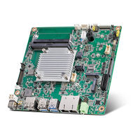
Advantech AIMB-218ZS0A1E User Manual (108 pages)
Intel Pentium J6425 & Celeron J6413 & Celeron N6211 & Atom x6413E Mini-ITX HDMI/DP/LVDS (or eDP), 6 COM, and Dual LAN, 8 USB, 1 M.2 B key and 1 M.2 E key, PCIe x1
Brand:
Advantech
| Category:
Motherboard
| Size: 4.68 MB
Table of Contents
Table of Contents
7
Chapter 1 General Information
11
Introduction
12
Features
12
Specifications
12
System
12
Memory
12
Input/Output
13
Graphics
13
Ethernet LAN
13
Industrial Features
13
Mechanical and Environmental Specifications
13
Jumpers and Connectors
14
Board Layout: Jumper and Connector Locations
16
AIMB-218 Board Diagram
17
Safety Precautions
18
Jumper Options
18
Setting Jumpers
18
CMOS Mode Selection (JCMOS1)
19
COM2 RS-232/422/485 Mode Selector (JSETCOM2)
19
Edp/Lvds Panel Voltage Selection (JLVDS1)
20
PSON1: ATX and at Mode Selector
20
JWDT1 + JOBS1: Watchdog Timer Output and OBS Beep
21
Beep
21
Case Open Pin Header Selection (JCASEOP_SW1)
21
Power Switch/Hdd Led/Smbus/Speaker Pin Header (JFP1)
22
LVDS JEIDA/VESA Selection (JLVDS_VCON1)
22
COM1 5V/12V/RI# Selection (JSETCOM1_V1)
23
Chapter 2 Connecting Peripherals
25
Introduction
26
DC Input DC-Jack Connector (DCIN1) & 4-Pin ATX 12V Power Supply Connector (ATX12V1)
26
HDMI & Displayport Connector (DP1+HDMI1)
26
USB Connector (USB12/USB34/USB56/USB78)
27
LAN Ports
27
Front HD Analog Audio Interface (FPAUD1)
28
HD Analog Audio Interface Line-Out (AUDIO1)
28
HD Digital Audio Interface (SPDIF1)
29
Audio Amplifier Output Connector (AMP1) BOM Optional
29
PCI Express X1 Slot (PCIEX1_1)
30
NGFF M.2 E-Key Connector for 2230 Module (M2E1)
30
NGFF M.2 B-Key Connector for 2242/2280/3042 Module (M2B1)
31
SATA Signal Connector (SATA1) & SATA Power Connector (SATA_PWR1)
31
Serial Ports (COM1 ~ COM6)
32
COM 2 Port (COM12)
32
SIM Card Connector (SIM1)
32
SPI Programming Pin Header (SPI_CN1)
33
SPI BIOS Flash Socket (SPI1)
33
ESPI Pin Header (ESPI1)
34
8-Bits General Purpose I/O Pin Header (GPIO1)
34
Low-Voltage Differential Signaling Interface & Embedded Displayport (LVDS_EDP1)
35
LVDS Backlight Inverter Power Connector (INV1)
35
SYSTEM FAN Power Connector (SYSFAN1)
36
DDR4 SO-DIMM Socket (DIMMA1/DIMMB1)
36
ATX Power Supply (5VSB) Connector (ATX_5VSB1)
37
Front Panel Connectors (JFP1)
37
ATX Soft Power Switch (JFP1/PWR_SW)
37
Reset (JFP1/RESET)
38
Hdd Led (Jfp1/Hddled)
38
External Speaker (JFP1/SPEAKER)
38
Chapter 3 BIOS Operation
39
Introduction
40
BIOS Setup
40
Main Menu
41
Advanced BIOS Features
42
Chipset Configuration Setting
60
System Agent (SA) Configuration
61
PCH-IO Configuration
65
Security Setting
72
Boot Setting
73
Save & Exit Configuration
74
Chapter 4 Software and Service Introduction
77
Introduction
78
Value-Added Software Services
78
Software API
78
Software Utility
80
Chapter 5 Chipset Software Install Utility
81
Before Installation
82
Introduction
82
Chapter 6 Graphics Setup
83
Introduction
84
Windows 10
84
Chapter 7 LAN Configuration
85
Introduction
86
Features
86
Installation
86
Windows 10 Driver Setup (Realtek 8111G)
86
Appendix A Pin Assignments
87
DC Input Phoenix Connector (DCIN1)
88
Displayport High (DP1+HDMI1)
88
Definition Multimedia Interface (DP1+HDMI1)
88
USB 3.0+2.0 Stack Connector (USB34)
89
USB 3.0 Stack Connector (USB34)
89
RJ45 1 Port (LAN1)
90
RJ45 2 Port (LAN12)
91
Front HD Analog Audio Interface (FPAUD1)
91
HD Analog Audio Interface Line-Out (AUDIO1)
92
HD Digital Audio Interface (SPDIF1)
92
Audio Amplifier Output Connector (AMP1)
92
PCI Express X1 Slot (PCIEX1_1)
93
NGFF M.2 E-Key Connector for 2230 Module (M2E1)
94
SATA Signal Connector (SATA1)
95
NGFF M.2 B-Key Connector for 2242/2280/3042 Module (M2B1)
96
USB 2.0 Pin Header (USB56)
97
COM 4 Port (COM3456)
98
SIM Card Connector (SIM1)
99
SPI Programming Pin Header (SPI_CN1)
99
SPI BIOS Flash Socket (SPI1)
100
USB 2.0 Pin Header (USB78)
100
ESPI Pin Header (ESPI1)
100
8-Bit General Purpose I/O Pin Header (GPIO1)
101
Case-Open Detect Connector (JCASE1)
101
COM 2 Port (COM12)
101
Power LED Pin Header (JFP2)
102
LVDS Backlight Inverter Power Connector (INV1)
102
SATA Power Connector (SATA_PWR1)
102
SYSTEM FAN Power Connector (SYSFAN1)
103
Mps's I2C/SMBUS Programming for +VCCIN Controller (JSMB1)
103
Low-Voltage Differential Signaling Interface (LVDS_EDP1)
104
Embedded Displayport (LVDS_EDP1)
105
ATX Power Supply (5VSB) Connector (ATX_5VSB1)
105
ATX 12V Power Supply Connector (ATX12V1)
106
Advertisement
Advertisement
Related Products
Advantech AIMB-218 Series
Advantech AIMB218L-S0A1E
Advantech AIMB-218DS0A1E
Advantech AIMB-218JS0A1E
Advantech AIMB-210
Advantech AIMB-214
Advantech AIMB-212
Advantech AIMB-213
Advantech AIMB-215
Advantech AIMB-215 B1
Advantech Categories
Motherboard
Computer Hardware
Desktop
Touch Panel
Network Router
More Advantech Manuals
Login
Sign In
OR
Sign in with Facebook
Sign in with Google
Upload manual
Upload from disk
Upload from URL