
Related Manuals for Advantech AIMB-203


Summary of Contents for Advantech AIMB-203
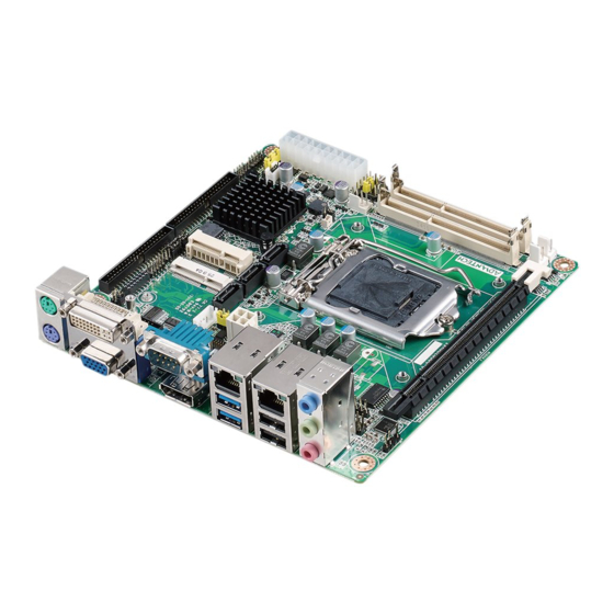
- Page 1 User Manual AIMB-203 Intel® Core™ i7/i5/i3/Pentium/ Celeron LGA1150 Mini-ITX with CRT/LVDS/DP++/DVI-D, 9 COM, 8 USB, Dual LAN, PCIe x16...
- Page 2 The documentation and the software included with this product are copyrighted 2014 by Advantech Co., Ltd. All rights are reserved. Advantech Co., Ltd. reserves the right to make improvements in the products described in this manual at any time without notice.
- Page 3 Whether your new Advantech equipment is destined for the labo- ratory or the factory floor, you can be assured that your product will provide the reliability and ease of operation for which the name Advantech has come to be known.
-
Page 4: Declaration Of Conformity
Intel® Haswell I5-4670K 3.4GHz Intel® Haswell I5-4570 3.2GHz Intel® Haswell I5-4570S 2.9GHz Intel® Haswell I5-4570TE 2.7GHz Intel® Haswell I3-4330 3.5GHz Intel® Haswell Pentium G3420 3.2GHz Intel® Xeon® Processor E3-1268L(V3) 2.3GHz Intel® Haswell Celeron G1820 2.7GHz Intel® Haswell Celeron G1820TE 2.2GHz AIMB-203 User Manual... - Page 5 PASS 1333 DDR3 R (256x8) ELPIDA DDR3 SODIMM 78.B2GC9.421 Apacer J2108BCSE- PASS 1333 DDR3 DJ-F ELPIDA DDR3 SODIMM 78.B2GC9.421 Apacer J2108ECSE- PASS 1333 DDR3 DJ-F 256x8 ELPIDA DDR3 SODIMM 78.C2GCM.42 Apacer J4208BASE- PASS 1333 DDR3 DJ-F 512x8 AIMB-203 User Manual...
- Page 6 IRM72 D9PFJ MICRON DDR3 SODIMM TS1GSK64V6 Transcend IZD27 D9PBC PASS 1600 DDR3 79T5 512x8 SEC 231 DDR3 SODIMM TS1GSK64W6 Transcend HYK0 PASS 1600 DDR3 K4B4G0846B SEC 140 DDR3 SODIMM AW24M64F8B HYK0 PASS 1600 DDR3 LK0S K4B4G0846B 512x8 AIMB-203 User Manual...
-
Page 7: Ordering Information
Because of Advantech’s high quality-control standards and rigorous testing, most of our customers never need to use our repair service. If an Advantech product is defec- tive, it will be repaired or replaced at no charge during the warranty period. For out- of-warranty repairs, you will be billed according to the cost of replacement materials, service time and freight. - Page 8 It should be free of marks and scratches and in perfect working order upon receipt. As you unpack the AIMB-203, check it for signs of ship- ping damage. (For example, damaged box, scratches, dents, etc.) If it is damaged or it fails to meet the specifications, notify our service department or your local sales representative immediately.
-
Page 9: Table Of Contents
Table 1.2: Jumper List ..............5 Board layout: Jumper and Connector Locations ........6 Figure 1.1 Jumper and Connector Location ........ 6 AIMB-203 Board Diagram ................. 7 Figure 1.2 AIMB-203 Board Diagram .......... 7 Safety Precautions ..................7 Jumper Settings ..................8 1.8.1 How to Set Jumpers.............. - Page 10 3.2.6 Save & Exit ................. 70 Chapter Software Introduction & Service ..71 Introduction ..................... 72 Value-Added Software Services ............. 72 4.2.1 Software API................72 Chapter Chipset Software Installation Utility Before You Begin..................76 Introduction ..................... 76 AIMB-203 User Manual...
- Page 11 CMOS Mode Selection (JCMOS1)............107 A.39 Power LED and Keyboard Lock Pin Header (JFP2) ......107 A.40 Power Switch/HDD LED/SMBus/Speaker Pin Header (JFP1) ....108 A.41 CPU FAN Connector (CPUFAN1)............108 A.42 System Fan1 Connector (SYSFAN1)............ 108 AIMB-203 User Manual...
- Page 12 A.43 System Fan2 Connector (SYSFAN2) ........... 109 A.44 SIM Card Holder (SIM2) ............... 109 AIMB-203 User Manual...
-
Page 13: Chapter 1 General Information
Chapter General Information... -
Page 14: Introduction
Introduction AIMB-203 is designed with the Intel® H81 for industrial applications that require both performance computing and enhanced power management capabilities. The mother- board supports Intel desktop Core i7-4770S 3.1GHz / Core i7-4770TE 2.3GHz / i5- 4570S 2.9GHz / i5-4570TE 2.7GHz / i3-4330 3.5GHz / i3-4330TE 2.4GHz / Pentium G3420 3.2GHz / Pentium G3320TE 2.3GHz / Celeron G1820 2.7GHz / Celeron... -
Page 15: Graphics
2.21A, +3.3V @ 1.03A, +12V @ 5.1A, 5VSB @ 0.4A Measure the maximum current value which system under maximum load (CPU: Top speed, RAM & Graphic: Full loading) Board size: 170 mm x 170 mm (6.69" x 6.69") Board weight: 0.365 kg AIMB-203 User Manual... -
Page 16: Jumpers And Connectors
Jumpers and Connectors Connectors on the AIMB-203 motherboard link it to devices such as hard disk drives and a keyboard. In addition, the board has a number of jumpers used to configure your system for your application. The tables below list the function of each of the board jumpers and connectors. Later sections in this chapter give instructions on setting jumpers. -
Page 17: Table 1.2: Jumper List
JSETCOM2_V1 COM2_RI# Pin RI#/5V/12V selection JSETCOM5 COM5 RS232,RS422,RS485 selection pin header JCMOS1 CMOS Mode selection JWDT1+JOBS1 Watchdog timer output and OBS beep JFP1 Power switch/HDD LED/SMBus/Speaker pin header PSON1 AT/ATX Mode selection JLVDS1 LVDS panel voltage selection AIMB-203 User Manual... -
Page 18: Board Layout: Jumper And Connector Locations
Board layout: Jumper and Connector Locations Figure 1.1 Jumper and Connector Location AIMB-203 User Manual... -
Page 19: Aimb-203 Board Diagram
4 RS-232 COM 4 x RS-232, 1 x RS-232/422/485, PS/2, WDT, LPT, 8 bit GPIO Figure 1.2 AIMB-203 Board Diagram Safety Precautions Warning! Always completely disconnect the power cord from chassis whenever you work with the hardware. Do not make connections while the power is on. -
Page 20: Jumper Settings
1.8.2 CMOS Clear (JCMOS1) The AIMB-203 motherboard contains a jumper that can erase CMOS data and reset the system BIOS information. Normally this jumper should be set with pins 1-2 closed. If you want to reset the CMOS data, set CMOS1 to 2-3 closed for just a few seconds, and then move the jumper back to 1-2 closed. -
Page 21: Com1_Ri# Pin Ri#/5V/12V Selection (Jsetcom1_V1)
Set COM1_RI# as RI# (Default) Set COM1_RI# as 5V Set COM1_RI# as 12V 1.8.5 COM2_RI# Pin RI#/5V/12V selection (JSETCOM2_V1) Table 1.6: COM2_RI# Pin RI#/5V/12V selection (JSETCOM2_V1) Function Setting Set COM2_RI# as RI# (Default) Set COM2_RI# as 5V Set COM2_RI# as 12V AIMB-203 User Manual... -
Page 22: Com5 Rs232,Rs422,Rs485 Selection Pin Header (Jsetcom5)
1.8.6 COM5 RS232,RS422,RS485 selection pin header (JSETCOM5) Table 1.7: COM5 RS232,RS422,RS485 selection pin header (JSETCOM5) Function Setting Set COM5 as RS-232 (Default) Set COM5 as RS-422 Set COM5 as RS-485 AIMB-203 User Manual... -
Page 23: Atx/At Mode Selection (Pson1)
Set LVDS Panel as +12V 1.8.9 Watchdog timer output and OBS beep (JWDT1+JOBS1) Table 1.10: Watchdog timer output and OBS beep (JWDT1+JOBS1) Function Setting Watchdog Timer Output(2-3) (Default) OBS BEEP(4-5) (Default) Watchdog Timer Disable(1-2) OBS BEEP(4-5) (Default) AIMB-203 User Manual... -
Page 24: Power Switch/Hdd Led/Smbus/Speaker Pin Header (Jfp1)
System Reset- System Memory AIMB-203 has two sockets for a 204-pin DDR3 SODIMM. This socket uses a 1.5 V unbuffered double data rate synchronous DRAM (DDR SDRAM). DRAM is available in capacities of 1 GB, 2 GB, 4 GB and 8 GB. The sockets can be filled in any combi- nation with SODIMMs of any size, giving a total memory size between 1 GB, 2 GB, 4 GB, 8 GB and 16 GB. -
Page 25: Cache Memory
1.11 Cache Memory The AIMB-203 supports a CPU with one of the following built-in full speed Last Level Cache: 8MB for Intel Core i7-4770S 8MB for Intel Core i7-4770TE 6MB for Intel Core i5-4570S 4MB for Intel Core i5-4570TE 3MB for Intel Core i3-4330... - Page 26 AIMB-203 User Manual...
-
Page 27: Chapter 2 Connecting Peripherals
Chapter Connecting Peripherals... -
Page 28: Introduction
USB Ports (LAN1_USB12/LAN2_USB34/USB56/ USB78) AIMB-203 provides up to eight USB ports. Two USB3.0 and two USB2.0 on the rear side and four pin header on the board. The USB interface complies with USB Specifi- cation Rev. 2.0 and Rev. 3.0 supporting transmission rates up to 625 Mbps and is fuse protected. -
Page 29: Dvi-D(Up) And Vga(Down) Connector (Vga1+Dvi1)
DVI-D(Up) and VGA(Down) connector (VGA1+DVI1) AIMB-203 includes VGA and DVI-D interfaces that can drive conventional VGA and DVI-D displays. VGA is a standard 15-pin D-SUB connector commonly used for VGA. Pin assignments for VGA and DVI-D connectors are detailed in Appendix A. -
Page 30: Serial Ports (Com1~Com9)
COM1 COM2 ~ COM5 box header (COM2345) COM6 ~ COM9 box header (COM6789) AIMB-203 supports nine serial ports. COM1~4 and COM6~9 supports RS-232 func- tion, COM5 supports RS-232/422/485 function by BIOS selection. COM1 and COM2 supports 5V/12V by jumper selection. -
Page 31: Ps/2 Keyboard And Mouse Connector (Kbms1)
Two 6-pin mini-DIN connectors (KBMS1) on the motherboard provide connection to a PS/2 keyboard and a PS/2 mouse, respectively. CPU Fan Connector (CPU_FAN1) If a fan is used, this connector supports cooling fans of 500 mA (6 W) or less. AIMB-203 User Manual... -
Page 32: System Fan Connector (Sysfan1/2)
System FAN Connector (SYSFAN1/2) If a fan is used, this connector supports cooling fans of 500 mA (6 W) or less. AIMB-203 User Manual... -
Page 33: Power Switch/Hdd Led/Smbus/Speaker Pin Header (Jfp1) & Power Led And Keyboard Lock Pin Header (Jfp2)
External speaker (JFP1/SPEAKER) JFP1/SPEAKER is a 4-pin connector for an external speaker. If there is no external speaker, the AIMB-203 provides an onboard buzzer as an alternative. To enable the buzzer, set pins 7 & 10 as closed. AIMB-203 User Manual... -
Page 34: Power Led And Keyboard Lock Connector
Connect pins 1 & 2 to (on back plane) pins 2-3 closed pins 1-2 closed panel switch via cable jumper setting System On System Suspend Fast flashes Fast flashes Fast flashes System Off Slow flashes Display Port (DP1) AIMB-203 User Manual... -
Page 35: Print Port Interface Box Header (Lpt1)
2.11 SATA Signal Connector (SATA1 ~ SATA3) SATA3 SATA2 SATA1 AIMB-203 features a high performance Serial ATA III & II interface (up to 600 MB/s & 300 MB/s) which eases hard drive cabling with thin, space-saving cables. AIMB-203 User Manual... -
Page 36: Hd Analog Audio Interface (Audio1, Fpaud1)
Front panel audio pin header (FPAUD1) Note! For motherboards with the optional HD Audio feature, we recommend that you connect a high-definition front panel audio module to this con- nector to take advantage of the motherboard’s high definition audio capability. AIMB-203 User Manual... -
Page 37: Pci-E X16 Slot (Pciex16_1)
2.13 PCI-E x16 Slot (PCIEX16_1) AIMB-203 provides 1 x PCI express x16 slot. 2.14 LVDS Panel Connector (LVDS1) AIMB-203 User Manual... -
Page 38: Lvds Backlight Inverter Power Connector (Inv1)
2.15 LVDS Backlight Inverter Power Connector (INV1) Note! Signal Description Signal Signal Description Vadj=0.75 V (Recommended: 4.7 KΩ, >1/16 W) ENBKL LCD backlight ON/OFF control signal AIMB-203 User Manual... -
Page 39: Minipcie And Msata Connector (Minipcie1)
2.16 MINIPCIE and mSATA Connector (MINIPCIE1) 2.17 MINIPCIE Connector (MINIPCIE2) & SIM Card Socket (SIM1) MINIPCIE connector (MINIPCIE2) AIMB-203 User Manual... -
Page 40: Hd Audio Interface Pin Header (Spdif1)
SIM Card holder (SIM2) 2.18 HD audio interface pin header (SPDIF1) AIMB-203 User Manual... -
Page 41: Audio Amplifier Output Connector (Jamp1)
2.19 Audio Amplifier Output Connector (JAMP1) 2.20 General Purpose I/O Pin Header (GPIO1) 2.21 SPI BIOS Flash Socket (SPI1) The SPI flash card pin header may be used to flash BIOS if the AIMB-203 cannot power on. AIMB-203 User Manual... -
Page 42: Low Pin Count Header (Lpc1)
2.22 Low Pin Count Header (LPC1) AIMB-203 User Manual... -
Page 43: Case-Open Detect Connector (Jcase1)
2.23 Case-Open Detect Connector (JCASE1) Signal CASEOP 2.24 ATX 12V Power Supply Connector (ATX12V1) & ATX Power Supply Connector (ATXPWR1) ATX 12V power supply connector (ATX12V1) ATX Power supply connector (ATXPWR1) AIMB-203 User Manual... -
Page 44: Cmos Battery Wafer Box (Bat1)
2.25 CMOS battery Wafer Box (BAT1) Signal BAT VCC 2.26 LGA 1150 CPU socket (CPU1) AIMB-203 User Manual... -
Page 45: Ddr3 So-Dimm Socket (Dimma1, Dimmb1)
2.27 DDR3 SO-DIMM Socket (DIMMA1, DIMMB1) AIMB-203 User Manual... - Page 46 AIMB-203 User Manual...
-
Page 47: Bios Operation
Chapter BIOS Operation... -
Page 48: Introduction
AIMB-203 setup screens. BIOS Setup The AIMB-203 Series system has AMI BIOS built in, with a CMOS SETUP utility that allows users to configure required settings or to activate certain system features. The CMOS SETUP saves the configuration in the CMOS RAM of the motherboard. -
Page 49: Main Menu
Date using the <Arrow> keys. Enter new values through the keyboard. Press the <Tab> key or the <Arrow> keys to move between fields. The date must be entered in MM/DD/YY format. The time must be entered in HH:MM:SS format. AIMB-203 User Manual... -
Page 50: Advanced Bios Features
3.2.2 Advanced BIOS Features Select the Advanced tab from the AIMB-203 setup screen to enter the Advanced BIOS Setup screen. You can select any of the items in the left frame of the screen, such as CPU Configuration, to go to the sub menu for that item. You can display an Advanced BIOS Setup option by highlighting it using the <Arrow>... - Page 51 PCI Latency Timer Value to be programed into PCI Latency Timer Register. VGA Palette Snoop Enable or Disable VGA palette registers snooping. PERR# Generation Enable or Disable PERR# Generation. SERR#Generation Enable or Disable SERR# Generation. AIMB-203 User Manual...
- Page 52 Defines number of micro-seconds software that will wait before polling "Link Training" bit in link status register. Values range from 10 to 1000 uS. Unpopulated Links In order to save power, software will disable unpopulated PCI Express links, if this option set to 'Disable Link'. AIMB-203 User Manual...
- Page 53 This item allows users to enable or disable hibernation ACPI Sleep state This item allows users to set the ACPI sleep state Lock Legacy Resources This item allows users to lock legacy devices’ resources. S3 Video Repost Enable or disable video repost AIMB-203 User Manual...
- Page 54 3.2.2.3 Trusted Computing Security Device Support Enable or disable BIOS support for security device. 3.2.2.4 S5 RTC wake Settings Wake system with fixed time Enable or disable system wake on alarm event AIMB-203 User Manual...
- Page 55 3.2.2.5 CPU Configuration 3.2.2.6 SATA Configuration SATA Controller(s) This item allows users to enable or disable the SATA device. AIMB-203 User Manual...
- Page 56 SATA Mode Selection This item allows users to select mode of SATA controller(s). 3.2.2.7 INTEL Rapid Start Technology Intel® Rapid start technology This item allows users to enable or disable Intel rapid start technology. AIMB-203 User Manual...
- Page 57 PCH-FW page shows Intel ME FW information. MDES BIOS Status Code Enable or disable MDES BIOS Status Code. Me FW Image Re-Flash This item allows users to enable or disable Me FW image re-flash function. AIMB-203 User Manual...
- Page 58 Intel® Anti-theft Technology This item allows users to enable or disable Intel AT in BIOS for testing only. Enter Intel® AT Suspend Mode This item allows users to enable or disable enter Intel AT suspend mode func- tion. AIMB-203 User Manual...
- Page 59 Maximum time the device will take before it properly reports itself to the host controller. Mass storage device Mass storage device emulation type. 'AUTO' enumerates devices according to their media format. Optical drives are emulated as 'CDROM'. AIMB-203 User Manual...
- Page 60 3.2.2.11 Super IO Configuration AIMB-203 User Manual...
- Page 61 AIMB-203 User Manual...
- Page 62 Serial Port 6/7/8/9 This item will allow users to enable or disable serial port 6/7/8/9. Change Settings This item allows users to change the serial port 6/7/8/9 setting. AIMB-203 User Manual...
- Page 63 AIMB-203 User Manual...
- Page 64 AIMB-203 User Manual...
- Page 65 Serial Port 1/2/3/4/5 This item will allow users to enable or disable serial port 1/2/3/4/5. Change Settings This item allows users to change the serial port 1/2/3/4/5 setting. AIMB-203 User Manual...
- Page 66 This item allows users to change the parallel port setting. Device Mode This item allows users to change the device mode. Digital I/O GPI 0/1/2/3/4/5/6/7 This item will allow users to set up Digital I/O 0~7 to "input" or "output". AIMB-203 User Manual...
- Page 67 3.2.2.12 Smart Fan Mode Configuration CPU Fan Mode To enable or disable CPU smart fan. System Fan Mode To enable or disable System Smart Fan. AIMB-203 User Manual...
- Page 68 3.2.2.13 PC Health Status This Page Shows AIMB-203 PC Health Status. CPU Warning Temperature Use this to set the CPU warning temperature threshold. When the system CPU reaches the warning temperature, the buzzer will beep. ACPI Shutdown Temperature This screen allows users to set the CPU temperature at which the system will automatically shut down to prevent the CPU from overheating damage.
- Page 69 3.2.2.14 Serial Port Console Redirection Console Redirection This item allows users to enable or disable console redirection. AIMB-203 User Manual...
-
Page 70: Chipset
3.2.3 Chipset This page provides information of the chipset on AIMB-203. PCH-IO Configuration PCI Express Configuration Details of PCI Express items. AIMB-203 User Manual... - Page 71 This item allows users to enable or disable ASPM. DMI Link Extended Synch Control This item allows users to enable or disable DMI Link Extended Synch. PCIe-USB Glitch W/A This item allows users to enable or disable PCIe-USB Glitch W/A. AIMB-203 User Manual...
- Page 72 This item allows users to enable or disable the SENFE function. SECE This item allows users to enable or disable the SECE function. PME SCI This item allows users to enable or disable the PME SCI function. AIMB-203 User Manual...
- Page 73 Smart auto setting remembers the last setting, but auto mode does not. Using smart auto setting, USB devices may not be recognized when system rebooting with more than one USB device connected. BTCG Enables or disables the BTCG function. AIMB-203 User Manual...
- Page 74 3.2.3.3 PCH Azalia Configuration Azalia Control detection of the Azalia device. Disable = Azalia will be unconditionally disabled Enable=Azalia will be unconditionally enabled Auto=Azalia will be enabled if present, disabled otherwise AIMB-203 User Manual...
- Page 75 3.2.3.4 System Agent (SA) Configuration Graphic Configuration Graphics Turbo IMON Current Graphics turbo IMON current values supported (14-31). Primary Display "Auto or IGFX or PEG” optimal to Primary Display. AIMB-203 User Manual...
- Page 76 Select the video device which will be activated during POST. Secondary boot display selection will appear based on customer's selection. LVDS Panel Type LVDS Panel Type selection. Backlight Signal Control Switch Backlight Signal Control for PWM or LINEAR. AIMB-203 User Manual...
- Page 77 This item allows users to enable or disable DMI Vcp. DMI Vcm Control This item allows users to enable or disable DMI Vcm. DMI Link ASPM Control This item allows users to select power management control. AIMB-203 User Manual...
- Page 78 Disabled: PCIe ASPM will be programmed before OpROM PEG0 De-emphasis Control Configure the De-emphasis control on PEG0. PEG0 ASPM Control ASPM support for the PEG Device. This has no effect if PEG is not the currently active device. AIMB-203 User Manual...
- Page 79 This item allows users to select the maximum TOLUD. Enh Interleave Support This item allows users to enable or disable EnH Interleave function. RI Support This item allows users to enable or disable RI support function. AIMB-203 User Manual...
-
Page 80: Boot
Select the Power-on state for Numlock. Quiet Boot If this option is set to Disabled, the BIOS display normal POST messages. If Enabled, an OEM Logo is shown instead of POST messages. Boot Option Priorities Set the system boot order. AIMB-203 User Manual... -
Page 81: Security
3.2.5 Security Select Security Setup from the AIMB-203 Setup main BIOS setup menu. All Security Setup options, such as password protection and virus protection are described in this section. To access the sub menu for the following items, select the item and press<Enter>: Change Administrator / User Password. -
Page 82: Save & Exit
This item allows you to restore the user defaults to all the options. Boot Override Boot device selection can override your boot priority. Launch EFI Shell from filesystem device Attempts to Launch EFI Shell application (Shellx64.efi) from one of the available filesystem devices. AIMB-203 User Manual... -
Page 83: Software Introduction & Service
Chapter Software Introduction & Service... -
Page 84: Introduction
Introduction The mission of Advantech Embedded Software Services is to "Enhance quality of life with Advantech platforms and Microsoft® Windows® embedded technology." We enable Windows® Embedded software products on Advantech platforms to more effectively support the embedded computing community. Customers are freed from the hassle of dealing with multiple vendors (hardware suppliers, system integrators, embedded OS distributors) for projects. - Page 85 System Throttling Refers to a series of methods for reducing power consump- tion in computers by lowering the clock frequency. This API allows the user to adjust the clock from 87.5% to 12.5%. AIMB-203 User Manual...
- Page 86 AIMB-203 User Manual...
-
Page 87: Chipset Software Installation Utility
Chapter Chipset Software Installation Utility... -
Page 88: Before You Begin
To facilitate the installation of the enhanced display drivers and utility software, read the instructions in this chapter carefully. The drivers for the AIMB-203 are located on the software installation CD. The driver in the folder of the driver CD will guide and link you to the utilities and drivers under a Windows system. -
Page 89: Windows 7/8 Driver Setup
Windows 7/8 Driver Setup Insert the driver CD into your system's CD-ROM drive. You can see the driver folder items. Navigate to the "Intel Chip" folder and click "infinst_autol.exe" to complete the installation of the driver. AIMB-203 User Manual... - Page 90 AIMB-203 User Manual...
-
Page 91: Chapter 6 Vga Setup
Chapter VGA Setup... -
Page 92: Introduction
Insert the driver CD into your system's CD-ROM drive. You can see the driver folders items. Navigate to the "Intel Graphics" folder and click "setup.exe" to complete the installation of the drivers for Windows 7 and Windows 8. AIMB-203 User Manual... -
Page 93: Chapter 7 Lan Configuration
Chapter LAN Configuration... -
Page 94: Introduction
Introduction The AIMB-203 has dual Gigabit Ethernet LANs via dedicated PCI Express x1 lanes (Realtek 8111E (LAN1) and Realtek 8111E(LAN2)) that offer bandwidth of up to 500 MB/sec, eliminating the bottleneck of network data flow and incorporating Gigabit Ethernet at 1000 Mbps. -
Page 95: Windows® 7/8 Driver Setup (Realtek 8111E)
Windows® 7/8 Driver Setup (Realtek 8111E) Insert the driver CD into your system's CD-ROM drive. Select the "Realtek GBE Con- troller" folder then navigate to the directory for your OS. AIMB-203 User Manual... - Page 96 AIMB-203 User Manual...
-
Page 97: Appendix A I/O Pin Assignments
Appendix I/O Pin Assignments... -
Page 98: Ps/2 Keyboard And Ps/2 Mouse Connector (Kbms1)
PS/2 Keyboard and PS/2 Mouse Connector (KBMS1) Signal Keyboard DATA Keyboard CLK Mouse DATA Mouse CLK DVI-D(Up) and VGA(Down) Connector (VGA1+DVI1) AIMB-203 User Manual... -
Page 99: Displayport Connector (Dp1)
DDC data TMDS DATA1- TMDS DATA1+ TMDS DATA 1/3 Shield Hot Plug Detect TMDS DATA0- TMDS DATA0+ DisplayPort connector (DP1) Signal Signal ML_LANE0+ ML_LANE0- ML_LANE1+ ML_LANE1- ML_LANE2+ ML_LANE2- ML_LANE3+ ML_LANE3- Config 1 AUX_CH+ AUX_CH- Hot Plug Detect +3.3V AIMB-203 User Manual... -
Page 100: Com1 Connector (Com1)
COM1 Connector (COM1) Signal Signal DCD# DSR# RST# CTS# DTR# RJ45+USB3.0 Stack Connector (LAN1_USB12) Signal Signal MDI_0+ MDI_0- MDI_1+ MDI_1- MDI_2+ MDI_2- MDI_3+ MDI_3- RX0- RX0+ TX0- TX0+ RX1- RX1+ TX1- TX1+ AIMB-203 User Manual... -
Page 101: Rj45+Usb2.0 Stack Connector (Lan2_Usb34)
RJ45+USB2.0 Stack Connector (LAN2_USB34) Signal Signal MDI_0+ MDI_0- MDI_1+ MDI_1- MDI_2+ MDI_2- MDI_3+ MDI_3- RX0- RX0+ TX0- TX0+ RX1- RX1+ TX1- TX1+ HD Analog Audio Interface (AUDIO1) Signal MIC IN LINE OUT LINE IN AIMB-203 User Manual... -
Page 102: Case Open Selection Pin Header (Jcaseop_Sw1)
(JCASEOP_SW1) Signal CASEOP# HWM_CASEOP# CASEOP Note: Setting Case Open w/ Normal Close or Open Switch. (2-3) is default. Case Open Pin Header (JCASE1) Signal CASEOP A.10 COM1 RI# Selection Pin Header (JSETCOM1_V1) Signal RI#_VCON RI#_VCON +12V RI#_VCON AIMB-203 User Manual... -
Page 103: Front Panel Audio Pin Header (Fpaud1)
A.11 Front Panel Audio Pin Header (FPAUD1) Signal MIC IN-L MIC IN-R FPAUD_DETECT# LINE OUT-R SENSE R1 SENSE LINE OUT-L SENSE R2 A.12 HD Audio Interface Pin Header (SPDIF1) Signal SPDIF OUT AIMB-203 User Manual... -
Page 104: Print Port Interface Box Header (Lpt1)
A.13 Print Port Interface Box Header (LPT1) Signal Signal STB# AFD# ERR# INIT# SLIN# ACK# BUSY SLCT A.14 LVDS VESA, JEIDA Format Selection Pin Header (JLVDS_VCON1) Signal +3.3V OPTION AIMB-203 User Manual... -
Page 105: Audio Amplifier Output Pin Header (Jamp1)
A.15 Audio Amplifier Output Pin Header (JAMP1) Signal AMP_OUT-L AMP_OUT-R A.16 COM2 RI# Selection Pin Header (JSETCOM2_V1) Signal RI#_VCON RI#_VCON +12V RI#_VCON AIMB-203 User Manual... -
Page 106: Lvds Backlight Inverter Power Connector (Inv1)
A.17 LVDS Backlight Inverter Power Connector (INV1) Signal +12V BKL_EN BKL_CTRL A.18 LVDS Panel Voltage Selection (JLVDS1) Signal +12V LVDS_VDD +3.3V AIMB-203 User Manual... -
Page 107: Lvds Panel Connector (Lvds1)
A.19 LVDS Panel Connector (LVDS1) Signal Signal LVDS DETECT# OD0- ED0- OD0+ ED0+ OD1- ED1- OD1+ ED1+ OD2- ED2- OD2+ ED2+ OCK- ECK- OCK+ ECK+ DDC CLK DDC DAT OD3- ED3- OD3+ ED3+ LVDS ENBKL LVDS VCON AIMB-203 User Manual... -
Page 108: Atx 12V Power Supply Connector (Atx12V1)
A.20 ATX 12V Power Supply Connector (ATX12V1) Signal +12V +12V A.21 Low Pin Count Interface Header (LPC1) Signal Signal LPC CLK (33MHz) RESET# FRAME# +3.3V SMBus CLK SERIRQ SMBus DAT +5VSB AIMB-203 User Manual... -
Page 109: 8-Bit General Purpose I/O Pin Header (Gpio1)
CTS# [3] DTR# [3] RI [3] DCD# [4] DSR# [4] RXD [4] RST# [4] TXD [4] CTS# [4] DTR# [4] RI [4] DCD# [5] DSR# [5] RXD [5] RST# [5] TXD [5] CTS# [5] DTR# [5] RI [5] AIMB-203 User Manual... -
Page 110: Com5 Rs232,Rs422,Rs485 Selection Pin Header (Jsetcom5)
SOUT [5] DCD# [5] COM_SOUT [5] TX_485- RX_485+ SIN [5] DTR [5] COM_SIN [5] DTR# [5] TX_485+ RX_485- A.25 MINIPCIE, mSATA Connector (MINIPCIE1) MINIPCIE: Signal Signal WAKE# +3.3Vaux Reserved Reserved +1.5V CLKREQ# Reserved Reserved REFCLK- Reserved REFCLK+ Reserved AIMB-203 User Manual... - Page 111 +3.3Vaux +3.3Vaux Reserved V1.2_DETECT# LED_WLAN# Reserved Reserved Reserved +1.5V Reserved MSATA_DETECT# +3.3Vaux mSATA: Signal Signal Reserved +3.3V Reserved Reserved +1.5V Reserved Reserved Reserved Reserved Reserved Reserved Reserved Reserved Reserved Reserved Reserved DETECT# Reserved +3.3V +1.5V SMB_CLK SMB_DATA AIMB-203 User Manual...
-
Page 112: Minipcie Connector (Minipcie2)
Reserved Reserved Reserved Reserved Reserved +1.5V Reserved MSATA_DETECT# +3.3V A.26 MINIPCIE Connector (MINIPCIE2) Signal Signal WAKE# +3.3Vaux Reserved Reserved +1.5V CLKREQ# UIM_PWR UIM_DATA REFCLK- UIM_CLK REFCLK+ UIM_RESET UIM_VPP Reserved Reserved Reserved DETECT# PERST# PCIE_RX- +3.3Vaux PCIE_RX+ +1.5V AIMB-203 User Manual... -
Page 113: Serial Ata Interface Connector (Sata1~Sata3)
USB_D+ +3.3Vaux +3.3Vaux Reserved V1.2_DETECT# LED_WLAN# Reserved Reserved Reserved +1.5V Reserved Reserved +3.3Vaux A.27 Serial ATA Interface Connector (SATA1~SATA3) Signal A.28 PCI-Express x16 Slot (PCIEX16_1) Signal Signal +12V PRSNT1# +12V +12V +12V +12V SMB_CLK Reserved SMB_DATA Reserved AIMB-203 User Manual... - Page 114 RX1+ RX1- TX2+ TX2- RX2+ RX2- TX3+ TX3- RX3+ Reserved RX3- Reserved CONFIG2 TX4+ Reserved TX4- RX4+ RX4- TX5+ TX5- RX5+ RX5- TX6+ TX6- RX6+ RX6- TX7+ TX7- RX7+ Reserved RX7- TX8+ Reserved TX8- RX8+ RX8- TX9+ AIMB-203 User Manual...
-
Page 115: Spi Bios Flash Socket (Spi1)
RX11+ RX11- TX12+ TX12- RX12+ RX12- TX13+ TX13- RX13+ RX13- TX14+ TX14- RX14+ RX14- TX15+ TX15- RX15+ Reserved RX15- Reserved A.29 SPI BIOS Flash Socket (SPI1) Signal Signal MOSI MISO WP# / IO2 HOLD# / IO3 +3.3V AIMB-203 User Manual... -
Page 116: Com6 ~ Com9 Box Header (Com6789)
DCD# [8] DSR# [8] RXD [8] RST# [8] TXD [8] CTS# [8] DTR# [8] RI [8] DCD# [9] DSR# [9] RXD [9] RST# [9] TXD [9] CTS# [9] DTR# [9] RI [9] A.31 LGA 1150 CPU Socket (CPU1) AIMB-203 User Manual... -
Page 117: Dual Port Usb2.0 Pin Header (Usb78)
A.32 Dual Port USB2.0 Pin Header (USB78) Signal Signal A.33 Dual Port USB2.0 Pin Header (USB56) Signal Signal A.34 Watchdog Timer Output and OBS Beep (JWDT1+JOBS1) Signal RESET# SIO BEEP FRP BEEP AIMB-203 User Manual... -
Page 118: At/Atx Mode Selection (Pson1)
A.35 AT/ATX Mode Selection (PSON1) Signal VCCAT +3.3V VCCATX A.36 ATX Power Supply Connector (ATXPWR1) Signal Signal +3.3V +3.3V +3.3V -12V PSON# POWER_OK +5VSB +12V AIMB-203 User Manual... -
Page 119: Cmos Battery Wafer Box (Bat1)
A.37 CMOS Battery Wafer Box (BAT1) Signal BAT VCC A.38 CMOS Mode Selection (JCMOS1) Signal RTC RESET# A.39 Power LED and Keyboard Lock Pin Header (JFP2) Signal LED Power Keyboard LOCK# AIMB-203 User Manual... -
Page 120: Power Switch/Hdd Led/Smbus/Speaker Pin Header (Jfp1)
Signal Signal HDD LED+ Power Button+ HDD LED- Power Button- SPK_P3 SMB_DATA System Reset+ SPK_P4 SMB_CLK System Reset- A.41 CPU FAN Connector (CPUFAN1) Signal +12V DETECT PWM IN A.42 System Fan1 Connector (SYSFAN1) Signal FAN POWER DETECT AIMB-203 User Manual... - Page 121 A.43 System Fan2 Connector (SYSFAN2) Signal FAN POWER DETECT A.44 SIM Card Holder (SIM2) Signal UIM_PWR UIM_RESET UIM_CLK Reserved UIM_VPP UIM_DATA Reserved AIMB-203 User Manual...
- Page 122 No part of this publication may be reproduced in any form or by any means, electronic, photocopying, recording or otherwise, without prior written permis- sion of the publisher. All brand and product names are trademarks or registered trademarks of their respective companies. © Advantech Co., Ltd. 2014...
Need help?
Do you have a question about the AIMB-203 and is the answer not in the manual?
Questions and answers