Table of Contents
Advertisement
Quick Links
VERTICAL LADDER
INSTALLATION INSTRUCTIONS
IMPORTANT NOTES: Read First
(A) Use liquid thread lock (such as Loctite
curing) helps to eliminate the common problem of "thread seizure" in stainless steel hardware by serving as a
lubricant during assembly.
(B) Do not pour concrete until the equipment is completely assembled, leveled and plumbed. Concrete must be
allowed to cure completely before using the equipment (at least 72 hours).
(C) Refer to Installation Manual for 1309 Half Wall installation instructions.
(D) An appropriate energy absorbing safety surface is required under and around all playground equipment.
Loose fill protective surfacing is shown only as an example for the purpose of this assembly instruction. Other
surfacing material may vary in thickness and/or compression depths. See free publication - The Handbook for
Public Playground Safety, Publication #325 at www.cpsc.gov for the surfacing appropriate for the fall height of
the equipment or consult your surfacing supply representative.
See Footing Detail
®
) with all threaded hardware. Important: Liquid thread lock (prior to
Figure 1.1
Manufactured by Krauss Craft, Inc.
www.playcraftsystems.com
See Installation Manual
Section 1309 Half Wall
For Customer Service Call
800.333.8519 (U.S.A.) or
541.955.9199 (International)
1210
Page 1 of 3
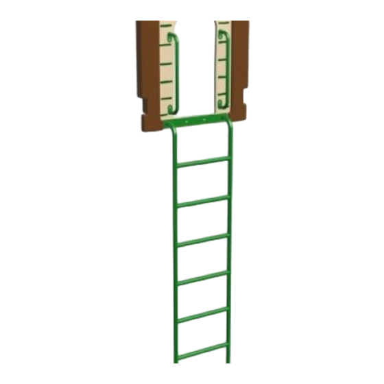
FIGURE 1
Vertical Ladder
NOTE: R5 5' Vertical Ladder shown.
Other configurations will vary slightly,
but does not affect assembly.
Rev E
4/4/2013
Advertisement
Table of Contents

Related Manuals for Playcraft 1210

Summary of Contents for Playcraft 1210
- Page 1 VERTICAL LADDER 1210 INSTALLATION INSTRUCTIONS Page 1 of 3 IMPORTANT NOTES: Read First ® (A) Use liquid thread lock (such as Loctite ) with all threaded hardware. Important: Liquid thread lock (prior to curing) helps to eliminate the common problem of "thread seizure" in stainless steel hardware by serving as a lubricant during assembly.
- Page 2 VERTICAL LADDER 1210 INSTALLATION INSTRUCTIONS Page 2 of 3 Step 1 Footing Detail Refer to Footing Layout and mark footing hole locations. Dig (2) Ø 12" footing holes. Refer to Footing Detail for depth and details. IMPORTANT: For areas with soft soil conditions, larger footings may be required.
- Page 3 VERTICAL LADDER 1210 INSTALLATION INSTRUCTIONS Page 3 of 3 Step 2 Attach Half Walls to Deck. Place Vertical Ladder into footing holes and attach to deck as shown in Figure 1.1. (See Notes A & C) DECK Step 3 Fully tighten all fasteners according to the "TIGHTENING TORQUE FOR HARDWARE"...
Need help?
Do you have a question about the 1210 and is the answer not in the manual?
Questions and answers