Advertisement
Quick Links
ERP机型:
PL3568FNQ-GL-SMT00011A-V1
描述:安装指引:PL3568FNQ/PGD688FN,SMT000,REV.D(IMPGD68820200728),196x196mm,
128g双粉纸, 双面印4C+2专色,过哑油,装订本14页28面(其中有一张折叠页),
RoHS2.0,REACH,Prop65,POPs,PAHs
C
C
M
M
2915C
2915C
7540C
2915C
Designed:曹显贵
Y
Y
K
K
Date:2020-07-28
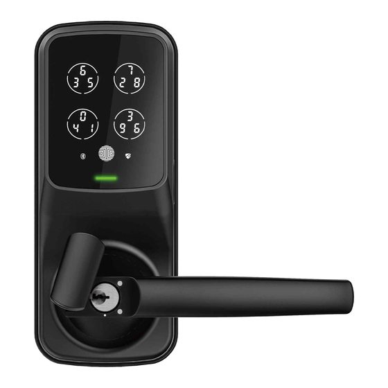
LUX COMPACT
INSTALLATION
MORTISE EDITION
REV:0.5
ERP P/N:
MANUAL
Advertisement

Related Manuals for Lockly LUX COMPACT PGD688FSN


Summary of Contents for Lockly LUX COMPACT PGD688FSN
- Page 1 REV:0.5 ERP机型: ERP P/N: PL3568FNQ-GL-SMT00011A-V1 描述:安装指引:PL3568FNQ/PGD688FN,SMT000,REV.D(IMPGD68820200728),196x196mm, 128g双粉纸, 双面印4C+2专色,过哑油,装订本14页28面(其中有一张折叠页), RoHS2.0,REACH,Prop65,POPs,PAHs 2915C 2915C 2915C 7540C Designed:曹显贵 Date:2020-07-28 LUX COMPACT INSTALLATION MANUAL MORTISE EDITION...
- Page 3 This lock can be installed for both right swing and left swing doors. The lock ships ready for a right swing door installation. INSTALLATION OVERVIEW & PARTS LIST If you wish to change the orientation of the lock for a Left Swing door, go to Step 4 for instructions. Battery Cover PM5 x 25MM Screw, Door thickness 1-19/50"~1-69/100"(35~43mm) BM4 ×...
- Page 5 GETTING STARTED - YOU WILL NEED All the parts you need to install the Lockly ® Lux Compact is included in your package. However, we do need a few tools. Required Tools Optional Flathead Screwdriver Phillips Screwdriver Screwdriver with drill bits...
- Page 6 STEP 1: ADJUSTING LOCKSET TO YOUR DOOR ORIENTATION There are 4 common door-opening directions, the lockset ships default for is for RIGHT IN-SWING Doors. You may skip this step if you are sure your door is a Right In-Swing Door. Otherwise, see the illustrations below to confirm your door opening direction and change your latch throw orientation if needed.
- Page 7 RIGHT OUT-SWING DOOR Make sure the latch throw is correctly oriented as shown to fit your right out-swing door. RIGHT IN-SWING DOOR Make sure the latch throw is correctly oriented as shown to fit your right in-swing door.
- Page 8 HOW TO ADJUST THE LATCH THROW The Factory setting or the throw is for right in-swing door. You do not need to change direction if you have a right in-swing door. Here is here is how to change the latch throw direction. 1、Move the metal barrier upwards.
-
Page 9: Step 2: Preparing The Door
STEP 2: PREPARING THE DOOR Use provided drilling templates to prepare door for installation. You would need professional door drilling tools. Exterior Panel for Part B 1/2" 12mm 4-7/50" 105mm Interior Panel for Part N 2-1/8" 54mm 2-3/8"(60mm) - Page 10 3. INSTALLING THE LOCKSET (PART F) 3.1 When installing the lockset, ensure the latch is at the top position and deadbolt is at the bottom. 3.2 Use provide screws (G) to secure the lockset position.
- Page 11 STEP 4: CHANGING HANDLE ORIENTATION FOR RIGHT OR LEFT SWING DOORS The lock ships default for Right Swing Doors. You may skip STEP 4 if your door is a Right Swing Door. To change your door handle orientation for a left swing door,please continue reading.
- Page 12 Use the provided Clamping tool (R) to push in the two metal pins at the base of the lock handle, located at the 3 o’clock and 9 o’clock positions, and remove the handle once the pins are compressed. Rotate the handle 180 degrees to the other side of the lock.
- Page 13 Confirm that your installation was complete by checking if the pins are flush against the handle, and has popped out. Adjust the handle accordingly to make sure the pins are fully decompressed and sits flush gainst the surface. Check that yor handle works smoothly by giving it a turn up and down.
- Page 14 Remove the screw position on point "R" Use a flathead screwdriver to press the middle marker and move to point "L". Insert the removed screw from point "R" screw tightly to point "L".
- Page 15 Changing the Interior Handle Orientation 4.10 Remove the screw by turning counter clockwise. Then rotate the handle 180° in the direction of the arrow until the screw hole aligns with marker as shown. 4.11 Securely screw clockwise as shown to complete your handle orienta- tion change.
- Page 16 STEP 5: INSTALLING PART C Install Spindle (C) with the holes side into the base of the lock Carefully bend the end of the locking and align the holes locate in pin (D) with a needle nose pliers. the 3 o’clock and 9 o’clock position.
- Page 17 STEP 6: INSTALLATING THE LOCK (EXTERIOR) Install the exterior lock as shown to the left by aligning the lock straight and passing the cable and attached rods through the lockset. Exterior Pass the Spindle (C) through Align the lock straight and press hard the center of the lockset, and (if you use the 3M tape in step 5.4) to the round rods through the sides...
- Page 18 STEP 7: INSTALLING THE LOCK (INTERIOR) Insert Positioning Rods (V) into the the holes to the left and right of the Spindle (C). The holes are located at the 3 Interior o’clock and 9 o’clock positions. Interior Mounting Plate (LK) will go against the interior side of your door.
- Page 19 Pull the cable from the exterior lock through the rectangular hole underneath the positioning rods and spindle. Remove the position rods (V) and replace them with screws (O) Tighten clockwise until the mounting plate is secure. *Secure top with M1 or M2 * If you have drilled a hole on the top in Step 1, please secure the hole with screw M1 or M2 depending...
- Page 20 Plug the cable that is coming through the door into the lock interior. Make sure you match the direction of the plug correctly and matching the red side of the plug with the red side on the lock. Secure the connection by ensuring the snap is inserted tightly.
- Page 21 Once the Interior lock is flush against the mounting plate, secure the lock to the plate by screwing clockwise by using supplied screws (P). Insert 4 AA batteries into the lock by matching the postive (+) and negative (-) orientation markings on the batteries to the battery chamber.
- Page 22 STEP 8: INSTALLING THE DOOR STRIKE Install the strike box as shown below. Open the door frame, install box, then the strike plate and fix it with screws. After the installation is completed, check if the lock is working smoothly. From the INDOOR, while the door is open, lift the handle to check if the lock opened and closed smoothly and whether the deadbolt and latch are fully extended to the strike.
- Page 23 STEP 9: DOWNLOAD THE LOCKLY ® Congratulations! You have completed the Lockly ® physical lock installation. To complete your setup, download the Lockly ® app from the iOS or Google Play app Store and follow on-screen instructions. Scan or visit Lockly.com/app...
- Page 24 PGH200 SECURE LINK You can add live status monitoring and voice control capabilities to your Lockly Smart Lock with ® Amazon Alexa or Google Assistant via installing the Secure Link Wi-Fi Hub and Door Sensors (Sold Separately) Know it’s Closed.
- Page 25 FCC Warning: This device complies with Part 15 of the FCC Rules. Operation is subject to the following two conditions: (1) This device may not cause harmful interference, and (2) this device must accept any interference received, including interference that may cause undesired operation. NOTE 1: This equipment has been tested and found to comply with the limits for a Class B digital device, pursuant to part 15 of the FCC Rules.
- Page 26 L’émetteur/récepteur exempt de licence contenu dans le présent appareil est conforme aux CNR d’Innovation, Sciences et Développement économique Canada applicables aux appareils radio exempts de licence. L’exploitation est autorisée aux deux conditions suivantes: 1. L’appareil ne doit pas produire de brouillage; 2.
- Page 27 LUX COMPACT We’re here to help! help@lockly.com https://lockly.com/help IMPGD68820200728...
- Page 28 LUX COMPACT For the latest version of this installation guide, please visit the following link: http://lockly.com/help...
Need help?
Do you have a question about the LUX COMPACT PGD688FSN and is the answer not in the manual?
Questions and answers
After thedoir is opened to leave, the thing keeps chirping and clicking and won't let me set the deadbolt. How do I turn that off?