
Subscribe to Our Youtube Channel
Related Manuals for ProLights DIGIDRIVERIP


Summary of Contents for ProLights DIGIDRIVERIP
- Page 1 DIGIDRIVERIP DIGISTRIPIP50 DIGISTRIPIP100 MASTER DRIVER PIXEL-MAP LED BAR USER MANUAL MANUALE UTENTE EN - IT...
- Page 2 All rights reserved by Music & Lights S.r.l. No part of this instruction manual may be reproduced in any form or by any means for any commercial use. In order to improve the quality of products, Music&Lights S.r.l. reserves the right to modify the characteristics stated in this instruction manual at any time and without prior notice.
-
Page 3: Table Of Contents
DIGIDRIVERIP - DIGISTRIPIP50 - DIGISTRIPIP100 TABLE OF CONTENTS Safety General instructions Warnings and installation precautions 1 Description and Technical specifications 1. 1 DIGIDRIVERIP 1. 2 DIGISTRIPIP50 1. 3 DIGISTRIPIP100 1. 4 Operating elements and connections 2 Installation 2. 1 Mounting 2. -
Page 4: General Instructions
DIGIDRIVERIP - DIGISTRIPIP50 - DIGISTRIPIP100 WARNING! Before carrying out any operations with the unit, carefully read this instruction manual and keep it with cure for future reference. It contains important information about the installation, usage and maintenance of the unit. -
Page 5: Digidriverip
20 DIGISTRIPIP100s and 40 DIGISTRIPIP50s - each offering the control of up to 3.600 pixels in a one rack unit, offering 20 DMX universes and 546 W of power in and out. DIGIDRIVERIP cannot control DIGISTRIP, DIGITUBE and DIGITILE. DIGIDRIVERIP is compatible with Art-Net, Kling-Net and sACN protocols and runs signal and power over a 4 pole XLR cable that allow wiring of units in a chain. -
Page 6: Digistripip50
The external con- trol unit DIGIDRIVERIP is compatible with Art-Net and Kling-Net protocol and runs both signal and power over a 4 pole cable that provides greater stability and connection in a daisy chain (up to 40 DIGISTRIPIP50). -
Page 7: Digistripip100
The external control unit DIGIDRIVERIP is compatible with Art-Net and Kling-Net protocol and runs both signal and power over a 4 pole cable that provides greater stability and connection in a daisy chain (up to 20 DIGISTRIPIP100) LIGHT SOURCE •... -
Page 8: Operating Elements And Connections
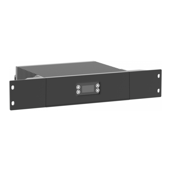
DIGIDRIVERIP - DIGISTRIPIP50 - DIGISTRIPIP100 1.4 OPERATING ELEMENTS AND CONNECTIONS Fig.4 1. MOUNTING HOLES for fixing the rack. 5. POWER OUT (PowerCON OUT): power output 2. CONTROL PANEL with display and 4 buttons for connection of multiple units in series. -
Page 9: Installation
- 2 - INSTALLATION 2.1 MOUNTING The management and power unit DIGIDRIVERIP should be placed on a non-flammable flat surface in any orientation or fixed by four screws in a 19” rack. There are four mounting holes on the housing as shown in figure 7. -
Page 10: Functions And Settings
3.1 BASIC SETUP The DIGIDRIVERIP has an OLED display and 4 buttons for access to the functions of the control panel (fig.6). DOWN... -
Page 11: Menu Structure
DIGIDRIVERIP - DIGISTRIPIP50 - DIGISTRIPIP100 3.3 MENU STRUCTURE MAIN LEVEL Remark ð AUTO ADDRESS No - Yes ð VIEM LINKED Port A 1.DIGISTRIPIP100 FIXTURES 2.DIGISTRIPIP100 3.DIGISTRIPIP050 … Port B 1.DIGISTRIPIP100 2.DIGISTRIPIP100 3.DIGISTRIPIP050 … ð LED OUTPUT Default: Off Green Blue... - Page 12 DIGIDRIVERIP - DIGISTRIPIP50 - DIGISTRIPIP100 ð PORT B Personality 7-CH-Drive Default : PixelTOPixel 8-CH-Fixture 13-CH-Fixture 2-Section 5-Section 10-Section 25-Section 50-Section PixelTOPixel ð 0-127 Default: 0 ð Subnet 0-15 Default: 0 ð Universe 0-15 Default: 0 ð sACN Universe 1-247 Default: 1 ð...
-
Page 13: Dmx Control
DIGIDRIVERIP - DIGISTRIPIP50 - DIGISTRIPIP100 3.4 DMX CONTROL Control Personalities 7 CHANNELS MODE FUNCTION Value 7 Ch MASTER DIMMER 0~100% 000 - 255 0~100% 000 - 255 GREEN 0~100% 000 - 255 BLUE 0~100% 000 - 255 AUTO PROGRAM No Function... - Page 14 DIGIDRIVERIP - DIGISTRIPIP50 - DIGISTRIPIP100 8 CHANNELS 8 CHANNELS MODE MODE FUNCTION FUNCTION Value Value 8 Ch 8 Ch DIMMER SPEED MODE MASTER DIMMER Dimmer speed mode off 000 - 101 0~100% 000 - 255 Dimmer speed mode1 (fast speed)
- Page 15 DIGIDRIVERIP - DIGISTRIPIP50 - DIGISTRIPIP100 13 CHANNELS 13 CHANNELS MODE MODE FUNCTION FUNCTION Value Value 13 Ch 13 Ch AUTO PROGRAM FOREGROUND DIMMER No Function 000 - 010 0~100% 000 - 255 Auto 1 011 - 020 FOREGROUND STROBE Auto 2...
- Page 16 DIGIDRIVERIP - DIGISTRIPIP50 - DIGISTRIPIP100 6 CHANNELS 15 CHANNELS 2-SECTION 5-SECTION FUNCTION FUNCTION Value Value 6 Ch 15 Ch RED 1 RED 1 0~100% 000 - 255 0~100% 000 - 255 GREEN 1 GREEN 1 0~100% 000 - 255 0~100%...
- Page 17 DIGIDRIVERIP - DIGISTRIPIP50 - DIGISTRIPIP100 30 CHANNELS 75 CHANNELS 10-SECTION 25-SECTION FUNCTION FUNCTION Value Value 30 Ch 75 Ch RED 1 RED 1 0~100% 000 - 255 0~100% 000 - 255 GREEN 1 GREEN 1 0~100% 000 - 255 0~100%...
- Page 18 DIGIDRIVERIP - DIGISTRIPIP50 - DIGISTRIPIP100 150 CHANNELS 300 CHANNELS 50-SECTION PixelTOPixel FUNCTION FUNCTION Value Value 150 Ch 300 Ch RED 1 RED 1 0~100% 000 - 255 0~100% 000 - 255 GREEN 1 GREEN 1 0~100% 000 - 255 0~100%...
-
Page 19: Connection Diagram
DIGIDRIVERIP - DIGISTRIPIP50 - DIGISTRIPIP100 - 4 - CONNECTION DIAGRAM 100cm Green Blue Black Male connector Female connector 1-Red 2-Green 4-Black 3-Blue... -
Page 20: Maintenance
DIGIDRIVERIP - DIGISTRIPIP50 - DIGISTRIPIP100 - 5 - MAINTENANCE 5.1 MAINTENANCE AND CLEANING THE UNIT • Make sure the area below the installation place is free from unwanted persons during setup. • All screws used for installing the device and any of its parts should be tightly fastened and should not be corroded. - Page 22 Music & Lights S.r.l. si riserva ogni diritto di elaborazione in qualsiasi forma delle presenti istruzioni per l’uso. La riproduzione - anche parziale - per propri scopi commerciali è vietata. Al fine di migliorare la qualità dei prodotti, la Music&Lights S.r.l. si riserva la facoltà di modificare, in qualunque momento e senza preavviso, le specifiche menzionate nel presente manuale di istruzioni.
- Page 23 DIGIDRIVERIP - DIGISTRIPIP50 - DIGISTRIPIP100 INDICE Sicurezza Avvertenze generali Attenzioni e precauzioni per l’installazione 1 Introduzione 1. 1 DIGIDRIVERIP 1. 2 DIGISTRIPIP100 1. 3 DIGISTRIPIP50 1. 4 Elementi di comando e collegamenti 2 Installazione 2. 1 Montaggio 2. 2 Distanza massima di cablaggio 3 Funzioni e impostazioni 3.
-
Page 24: Avvertenze Generali
DIGIDRIVERIP - DIGISTRIPIP50 - DIGISTRIPIP100 ATTENZIONE! Prima di effettuare qualsiasi operazione con l’unità, leggere con attenzione questo manuale e conservarlo accuratamente per riferimenti futuri. Contiene informazioni importanti riguardo l’installazione, l’uso e la manutenzione dell’unità. SICUREZZA Avvertenze generali • I prodotti a cui questo manuale si riferisce sono conformi alle Direttive della Comunità Europea e per- tanto recano la sigla . -
Page 25: Introduzione
- 1 - INTRODUZIONE 1.1 DIGIDRIVERIP DIGIDRIVERIP è un alimentatore e processore del DIGISTRIPIP. Ha 2 uscite e può controllare fino a 20 DI- GISTRIPIP100 o 40 DIGISTRIPIP50, ognuno con la possibilità di controllare fino a 3.600 pixels in una unità... - Page 26 L’unità di controllo esterna DIGIDRIVERIP è compatibile con i protocolli Art-Net e Kling-Net e trasmette sia segnale che alimentazione attraverso un cavo a 4 poli che offre una maggiore stabilità e connessione in catena (fino a 40 DIGISTRIPIP50).
-
Page 27: Digistripip100
L’unità di controllo esterna DIGIDRIVERIP è compatibile con i protocolli Art-Net e Kling-Net e trasmette sia segnale che alimentazione attraverso un cavo a 4 poli che offre una maggiore stabilità e connessione in catena (fino a 20 DIGISTRIPIP100). -
Page 28: Elementi Di Comando E Collegamenti
DIGIDRIVERIP - DIGISTRIPIP50 - DIGISTRIPIP100 1.4 ELEMENTI DI COMANDO E COLLEGAMENTI Fig.4 1. FORI DI FISSAGGIO per il montaggio rack. per l'alimentazione all'unità successiva. 2. PANNELLO DI CONTROLLO con display e 4 6. DMX OUT (XLR a 4 poli): 1= massa,2 = DMX -, pulsanti per accesso e gestione delle diverse 3 = DMX +, 4 N/C. -
Page 29: Installazione
- 2 - INSTALLAZIONE 2.1 MONTAGGIO L‘ unità di gestione e alimentazione DIGIDRIVERIP deve essere collocata in modo stabile su una superficie piana non infiammabile, oppure può essere montata in un rack da 19” per mezzo delle viti che devono essere inserite negli appositi fori presenti sul corpo del dispositivo, come mostrato in figura 7. -
Page 30: Funzioni E Impostazioni
Per spegnere il DIGIDRIVERIP, staccare la spina dalla presa di rete. Per maggiore comodità è consigliabile collegare l’unità con una presa comandata da un interruttore. 3.2 IMPOSTAZIONE BASE Il DIGIDRIVERIP dispone di un display OLED e 4 pulsanti per accesso alle funzioni del pannello di controllo (fig.6). DOWN... -
Page 31: Struttura Menu
DIGIDRIVERIP - DIGISTRIPIP50 - DIGISTRIPIP100 3.3 STRUTTURA MENU MAIN LEVEL Remark ð AUTO ADDRESS No - Yes ð VIEM LINKED Port A 1.DIGISTRIPIP100 FIXTURES 2.DIGISTRIPIP100 3.DIGISTRIPIP050 … Port B 1.DIGISTRIPIP100 2.DIGISTRIPIP100 3.DIGISTRIPIP050 … ð LED OUTPUT Default: Off Green Blue... - Page 32 DIGIDRIVERIP - DIGISTRIPIP50 - DIGISTRIPIP100 ð PORT B Personality 7-CH-Drive Default : PixelTOPixel 8-CH-Fixture 13-CH-Fixture 2-Section 5-Section 10-Section 25-Section 50-Section PixelTOPixel ð 0-127 Default: 0 ð Subnet 0-15 Default: 0 ð Universe 0-15 Default: 0 ð sACN Universe 1-247 Default: 1 ð...
- Page 33 DIGIDRIVERIP - DIGISTRIPIP50 - DIGISTRIPIP100 3.4 CANALI DMX Control Personalities 7 CHANNELS MODE FUNCTION Value 7 Ch MASTER DIMMER 0~100% 000 - 255 0~100% 000 - 255 GREEN 0~100% 000 - 255 BLUE 0~100% 000 - 255 AUTO PROGRAM No Function...
- Page 34 DIGIDRIVERIP - DIGISTRIPIP50 - DIGISTRIPIP100 8 CHANNELS 8 CHANNELS MODE MODE FUNCTION FUNCTION Value Value 8 Ch 8 Ch DIMMER SPEED MODE MASTER DIMMER Dimmer speed mode off 000 - 101 0~100% 000 - 255 Dimmer speed mode1 (fast speed)
- Page 35 DIGIDRIVERIP - DIGISTRIPIP50 - DIGISTRIPIP100 13 CHANNELS 13 CHANNELS MODE MODE FUNCTION FUNCTION Value Value 13 Ch 13 Ch AUTO PROGRAM FOREGROUND DIMMER No Function 000 - 010 0~100% 000 - 255 Auto 1 011 - 020 FOREGROUND STROBE Auto 2...
- Page 36 DIGIDRIVERIP - DIGISTRIPIP50 - DIGISTRIPIP100 6 CHANNELS 15 CHANNELS 2-SECTION 5-SECTION FUNCTION FUNCTION Value Value 6 Ch 15 Ch RED 1 RED 1 0~100% 000 - 255 0~100% 000 - 255 GREEN 1 GREEN 1 0~100% 000 - 255 0~100%...
- Page 37 DIGIDRIVERIP - DIGISTRIPIP50 - DIGISTRIPIP100 30 CHANNELS 75 CHANNELS 10-SECTION 25-SECTION FUNCTION FUNCTION Value Value 30 Ch 75 Ch RED 1 RED 1 0~100% 000 - 255 0~100% 000 - 255 GREEN 1 GREEN 1 0~100% 000 - 255 0~100%...
- Page 38 DIGIDRIVERIP - DIGISTRIPIP50 - DIGISTRIPIP100 150 CHANNELS 300 CHANNELS 50-SECTION PixelTOPixel FUNCTION FUNCTION Value Value 150 Ch 300 Ch RED 1 RED 1 0~100% 000 - 255 0~100% 000 - 255 GREEN 1 GREEN 1 0~100% 000 - 255 0~100%...
- Page 39 DIGIDRIVERIP - DIGISTRIPIP50 - DIGISTRIPIP100 - 4 - SCHEMA DI COLLEGAMENTO 100cm Green Blue Black Male connector Female connector 1-Red 2-Green 3-Blue 4-Black...
- Page 40 DIGIDRIVERIP - DIGISTRIPIP50 - DIGISTRIPIP100 5 - MANUTENZIONE 5.1 MANUTENZIONE E PULIZIA DEL SISTEMA • Durante gli interventi, assicurarsi che l’area sotto il luogo di installazione sia libera da personale non qualificato. • Tutte le viti utilizzate per l’installazione dell’unità e le sue parti devono essere assicurate saldamente e non devono essere corrose.
- Page 44 MUSIC & LIGHTS S.r.l. - Phone +39 0771 72190 - www.musiclights.it...
Need help?
Do you have a question about the DIGIDRIVERIP and is the answer not in the manual?
Questions and answers