
Related Manuals for Spirit CVC800


Summary of Contents for Spirit CVC800
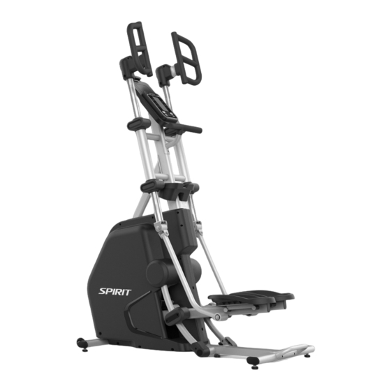
- Page 1 Owner’s Manual Model No. 16807098000 CVC800 - Assembly - Operation - Adjustments - Parts - Warranty CAUTION: Read and understand this manual before operating unit Retain For Future Reference...
-
Page 2: Table Of Contents
TABLE OF CONTENTS Product Registration ................. 2 Safety Precautions ................... 4 Important Safety Instructions ..............5 Important Electrical Instructions ..............8 Important Operation Instructions .............. 8 Assembly Pack Checklist ............... 10 Assembly Instructions ................12 Operation of Your Vertical Climber ............17 Using a Heart Rate Transmitter .............. -
Page 3: Product Registration
CONGRATULATIONS ON YOUR NEW VERTICAL CLIMBER AND WELCOME TO THE SPIRIT FAMILY! Thank you for your purchase of this quality vertical climber from Dyaco Canada Inc. Your new vertical climber was manufactured by one of the leading fitness manufacturers in the world and is backed by one of the most comprehensive warranties available. - Page 4 BEFORE YOU BEGIN Thank you for choosing the SPIRIT CVC800 Vertical Climber. We take great pride in producing this quality product and hope it will provide many hours of quality exercise to make you feel better, look better, and enjoy life to its fullest. It's a proven fact that a regular exercise program can improve your physical and mental health.
-
Page 5: Safety Precautions
SAFETY PRECAUTIONS IMPORTANT SAFETY INFORMATION THIS UNIT IS INTENDED FOR HOUSEHOLD USE ONLY READ ALL INSTRUCTIONS BEFORE USING THIS VERTICAL CLIMBER CAUTION: Before starting any exercise program, it is recommended that you consult your physician. Thank you for purchasing our product. Even though we go to great efforts to ensure the quality of each product we produce, occasional errors and/or omissions do occur. -
Page 6: Important Safety Instructions
IMPORTANT SAFETY INSTRUCTIONS WARNING - Read all instructions before using this equipment. DANGER - To reduce the risk of electric shock, disconnect your vertical climber from the electrical outlet prior to cleaning and/or service work. WARNING - To reduce the risk of burns, fire, electric shock, or injury to persons, install the vertical climber on a flat level surface with access to a 120-volt, 15-amp grounded outlet with only the vertical climber plugged into the circuit. - Page 7 Always unplug this equipment from the electrical outlet immediately after using and before cleaning. This equipment should never be left unattended when plugged in. Unplug from outlet when not in use, and before putting on or taking off parts. ...
- Page 8 First step: Please hold the stationary handlebar ( A1 position). Second step: Stand on the pedal ( B position). If you want to stop using the CVC800 climber, please follow the correct steps to get off: First step: Please stop workout from your climber.
-
Page 9: Important Electrical Instructions
IMPORTANT ELECTRICAL INSTRUCTIONS WARNING! NEVER remove any cover without first disconnecting AC power. If voltage varies by ten percent (10%) or more, the performance of your Vertical Climber may be affected. Such conditions are not covered under your warranty. If you suspect the voltage is low, contact your local power company or a licensed electrician for proper testing. - Page 10 GETTING ON / OFF YOUR CLIMBER IMPORTANT The climber comes with two Dual Action Handles and a Stationary Handlebar. Always hold the Stationary Handlebar (A1) when getting on and off the climber. First-time users should familiarize themselves with using the climber by using the Stationary Handlebar first and then progressing to the Dual Action Handles.
-
Page 11: Assembly Pack Checklist
ASSEMBLY PACK CHECKLIST HARDWARE STEP 1 126. Ø10 × 2T_ #125 Ø3/8" × 23 × 2.0T_ #119. Ø3/8" ×19 × 1.5T_ Split Washer(10pcs) Curved Washer (4pcs) Flat Washer (8pcs) #90. 3/8" × 3/4"_ #96. 3/8" × 3/4"_Socket Hex Head Bolt (2pcs) Head Cap Bolt (8pcs) #93. - Page 12 HARDWARE STEP 4 #100. M5× 10mm_ #102. 3.5 × 12mm_ Tapping Screw (18pcs) Sheet Metal Screw (6pcs) ASSEMBLY TOOLS #137. Phillips Head Screw Driver #138. M8_ L Allen Wrench #135. 13/14mm Wrench #136. 12/14mm Wrench #139. Short Phillips Head Screw Driver Customer Service 1-888-707-1880 Dyaco Canada Inc.
-
Page 13: Assembly Instructions
ASSEMBLY INSTRUCTIONS PRE-ASSEMBLY Carefully remove all parts from the carton and inspect for any damage or missing parts. If damaged parts are found or parts are missing, contact your dealer immediately. Locate the hardware package. The hardware is separated into four steps. Remove the tools first. - Page 14 REAR STABILIZER/CONSOLE MAST ASSEMBLY HARDWARE STEP 1 #93. 3/8" × 3-3/4"_ Hex Head Bolt (2 pcs) #90. 3/8" × 3/4"_ Hex Head Bolt (2 pcs) #96. 3/8" × 3/4"_Socket Head Cap Bolt (8 pcs) #119. Ø3/8" × 19 × 1.5T_Flat Washer (8 pcs) #125 Ø3/8"...
- Page 15 SIDE TUBE ASSEMBLY HARDWARE STEP 2 #88. 5/16"×15mm_ Hex Head Bolt (2pcs) #121. Ø5/16" × Ø23 × 1.5T_Flat Washer (2 pcs) #90. 3/8" × 3/4"_ Hex Head Bolt (2 pcs) #125. 3/8"×23×2.0T_ Curved Washer (2pcs) 1. Take off the axle & screw from the Right Driving Assembly (No.19), install the lower hole of Right Driving Assembly to the axle of Connecting Arm (R)(#8) to connect together, then firmly fasten one Hex Head Bolt (No.88) through one Flat Washer...
- Page 16 HANDGRIP ASSEMBLY HARDWARE STEP 3 #91. 3/8" × 2-1/4"_Hex Head Bolt (2 pcs) #92. 3/8" × UNC16 × 2-1/2"_Hex Head Bolt (4 pcs) #111. 3/8" × 7T_Nylon Nut (4 pcs) #119. Ø3/8" × Ø19 × 1.5T_Flat Washer (8 p #125. 3/8"×23×2.0T_ Curved Washer (2pcs) Install the Seat Handle Bar (No.15L) onto the upper Handgrip Stabilizer Assembly (No.11), firmly fasten one...
- Page 17 CONSOLE / COVERS ASSEMBLY HARDWARE STEP 4 #100. M5 × 10mm_ Tapping Screw (18 pcs) #102. 3.5 × 12mm_ Sheet Metal Screw (6 pcs) 1. Plug the Computer Cable (No.41) into Console Assembly (No.40). Install the Console Assembly on top of the mast of the Console Mast (No.2) (stuff rest cables into the mast tube), then firmly fasten 4 Tapping Screws (No.100) using the Screw Driver (No.137).
-
Page 18: Operation Of Your Vertical Climber
OPERATION OF YOUR VERTICAL CLIMBER Tablet Holder LCD Data Display Window Program Buttons Start, Stop, Level Controls POWER UP When the display is powered up, all characters on the console will light up. The LCD Data Display Window will show the software version, and the total time the climber has been used since it was new. - Page 19 Bluetooth® transceiver that will allow it to interact with selected phones or tablet computers via the Spirit+ App. Just download the free Spirit+ App from the Apple Store or Google Play, and then follow the instructions in the App to sync with your exercise machine.
- Page 20 PRESET PROGRAMS The Climber has five different programs that have been designed for a variety of workouts. These five programs have factory preset work level profiles for achieving different goals. HILL The Hill program simulates going up and down a hill. The resistance in the pedals will steadily increase and then decrease during the program.
- Page 21 STRENGTH The Strength program is designed to increase muscular strength in your lower body. This program will steadily increase in resistance to a high level and forces you to sustain it. This is designed to strengthen and tone your legs and glutes. HIIT The HIIT program takes you through high levels of intensity, followed by periods of low intensity.
- Page 22 HEART RATE PROGRAMS The old motto, "no pain, no gain", is a myth that has been overpowered by the benefits of exercising comfortably. A great deal of this success has been promoted by the use of heart rate monitors. With the proper use of a heart rate monitor, many people find that their choice of exercise intensity is either too high or too low and exercise is much more enjoyable by maintaining their heart rate in the desired benefit range.
- Page 23 RATE OF PERCEIVED EXERTION Heart rate is important but listening to your body also has a lot of advantages. There are more variables involved in how hard you should work out than just heart rate. Your stress level, physical health, emotional health, temperature, humidity, the time of day, the last time you ate and what you ate all contribute to the intensity at which you should workout.
-
Page 24: Using A Heart Rate Transmitter
USING HEART RATE TRANSMITTER (Optional) How to wear your wireless chest strap transmitter: 1. Attach the transmitter to the elastic strap using the locking parts. 2. Adjust the strap as tightly as possible as long as the strap is not too tight to remain comfortable. -
Page 25: Exploded View Diagram
EXPLODED VIEW DIAGRAM Customer Service 1-888-707-1880 Dyaco Canada Inc. 2021 Email: customerservice@dyaco.ca... -
Page 26: Parts List
PARTS LIST KEY NO. PART NO. DESCRIPTION Q'TY Main Frame CC010113-S13 Strap Hold Down CC040083-S13 Crank Arm CC060160-Q2 Crank Axle RC140032-01 Linked Assembly (L) RCC060161-S13 Linked Assembly (R) RCC060162-S13 Connecting Arm (L) RCC060184-S13 Connecting Arm (R) RCC060185-S13 Left Swing Assembly RCC060165-S13 Right Swing Assembly RCC060166-S13... - Page 27 KEY NO. PART NO. DESCRIPTION Q'TY Slide Wheel , Urethane RP050051-D5-02 Ø35 × 10m/m_Rubber Foot P060256-A1 50-1 Adjustment Foot P270036 Bushing P060440 Track Wheel P050065-A1 Sleeve P060633B-A1 Drive Pulley PP060090-A1-B 25.4 × 2.0T_Round Cap P040136-A1 Ø32 × 1.8T_Round Cap P040052-A1 Oval End Cap(30×60×2.5T) P040219-A1 Oval End Cap(Ø40×Ø80)
- Page 28 Q'TY KEY NO. PART NO. DESCRIPTION 3.5 × 12m/m_Sheet Metal Screw J396804-Y3 3.5 × 16m/m_Sheet Metal Screw J396805-Y3 5 × 19m/m_Tapping Screw J367114-Y3 5 × 16m/m_Tapping Screw J377105-Y3 Ø17_C Ring J310002-Z4 1/4" × 8T_Nylon Nut J139461-Z1 5/16" × 7T_Nylon Nut J139062-Y3 M8 ×...
- Page 29 ENGINEERING MODE The console has built-in maintenance/diagnostic software. The software will allow you to change the console settings from English to Metric and turn off the beeping of the speaker when a key is pressed, for example. To enter the Maintenance Menu (may be called Engineering Mode, depending on the version), press and hold down the Start, Stop and Enter keys;...
-
Page 30: Training Guidelines
TRAINING GUIDELINES EXERCISE Exercise is one of the most important factors in the overall health of an individual. Listed among its benefits are: Increased capacity for physical work (strength endurance) Increased cardiovascular (heart and arteries/veins) and respiratory efficiency Decreased risk of coronary heart disease ... - Page 31 Progression As your become fitter, a higher intensity of exercise is required to create an overload and therefore provide continued improvement Overload This is where you exercise at a level above that which can be carried out comfortably. The intensity, duration and frequency of exercise should be above the training threshold and should be gradually increased as the body adapts to the increasing demands.
- Page 32 The following table is a guide to those who are “starting fitness.” Target heart Rate 10 Second Count Beats per Minute 132 126 120 Pulse Count The pulse count (on your wrist or carotid artery in the neck, taken with two index fingers) is done for ten seconds, taken a few seconds after you stop exercising.
- Page 33 Muscle Soreness For the first week or so, this may be the only indication you have that you are on an exercise program. This, of course, does depend on your overall fitness level. A confirmation that you are on the correct program is a very slight soreness in most major muscle groups. This is quite normal and will disappear in a matter of days.
-
Page 34: Stretching
STRETCHING Stretching should be included in both your warm-up and cool-down and should be performed after 3-5 minutes of low-intensity aerobic activity or callisthenic type exercise. Movements should be performed slowly and smoothly, with no bouncing or jerking. Move into the stretch until slight tension; no pain is felt in the muscle and hold for 20-30 seconds. - Page 35 INNER THIGH STRETCH TOE TOUCHES Sit with the soles of your feet together Slowly bend forward from your waist, with your knees pointing outward. Pull letting your back and shoulders relax your feet as close to your groin as as you stretch toward your toes. Reach possible.
-
Page 36: Manufacturer's Limited Warranty
MANUFACTURER'S LIMITED WARRANTY Dyaco Canada Inc. warrants all its Spirit vertical climber for a period of time listed below, from the date of retail sale, as determined by a sales receipt. Dyaco Canada Inc.'s responsibilities include providing new or remanufactured parts, at Dyaco Canada Inc.'s option, and technical support to our independent dealers and servicing organizations. - Page 37 Please visit us online for information about our other brands and products manufactured and distributed by Dyaco Canada Inc. spiritfitness.ca solefitness.ca xterrafitness.ca dyaco.ca/products/everlast.html dyaco.ca/UFC/UFC-home.html spiritfitness.ca/johnnyg.html trainorsports.ca For more information, please contact Dyaco Canada Inc. T: 1-888-707-1880 ⏐ 5955 Don Murie St., Niagara Falls, Ontario L2G 0A9 ⏐ sales@dyaco.ca Customer Service 1-888-707-1880 Dyaco Canada Inc.
Need help?
Do you have a question about the CVC800 and is the answer not in the manual?
Questions and answers