
Related Manuals for Spirit CB900


Summary of Contents for Spirit CB900
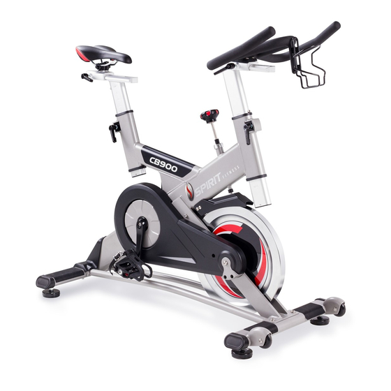
- Page 1 GROUP EXERCISE BIKE OWNER’S MANUAL PLEASE CAREFULLY READ THIS ENTIRE MANUAL BEFORE OPERATING YOUR GROUP BIKE!
-
Page 2: Table Of Contents
TABLE OF CONTENTS Important Safety Instructions……………………………………………………….…………3 Guidelines for Safe Operation…………………………………………………….…………..4 Hardware Assembly Pack……………………………………………………………………..5 Adjusting the Bike for a Proper Fit………………………………………………….………...9 How to Use Our Dual Function Pedal……………………….……………………….………10 Basic Operation / Maintenance Guidelines……………………………………….……..…..11 Parts list………………………………………………………………………………………….12 Exploded View Drawing..………………………………………………………………………15 CB700_1410D... -
Page 3: Important Safety Instructions
IMPORTANT SAFETY INSTRUCTIONS WARNING --READ ALL INSTRUCTIONS BEFORE USING THIS EXERCISE EQUIPENT Use this equipment only for its intended use as described in this manual. Do not attempt to ride this bike at high pedal speeds until you have ridden the bike for some time and are comfortable riding at slower pedal speeds. -
Page 4: Guidelines For Safe Operation
GUIDELINES FOR SAFE OPERATION WARNING! AS THE OWNER OF THIS EXERCISE EQUIPMENT, YOU SHOULD INSIST THAT ALL USERS FOLLOW THE SAME GUIDELINES: YOU SHOULD MAKE THIS MANUAL AVAILABLE TO ALL USERS. Obtain a complete physical examination from your medical doctor and enlist a health/fitness professional’s aid in developing an exercise program suitable for your current health status. -
Page 5: Hardware Assembly Pack
ASSEMBLY INSTRUCTIONS Pre-Assembly 1. Cut the straps, then pull the staples in the outer cardboard away from the layer beneath; lift the box over the unit and unpack. 2. Locate the hardware package. The hardware is separated into three steps. Remove the tools first. Remove the hardware for each step as needed to avoid confusion. - Page 6 Rear Stabilizer Assembly First, screw in two Leveling Glides (24) onto the Rear Stabilizer (3) and place the Rear Stabilizer (3) under the frame attaching plates at the rear end of the mainframe. Align the screw holes and insert two 3/8" × 2-1/4"_Button Head Socket Bolts (51) with 3/8" × 19 × 1.5T_Flat Washers (74) through the holes and tighten with 3/8"...
-
Page 7: Front Stabilizer Assembly
Front Stabilizer Assembly Screw in two Leveling Glides (24) onto the Front Stabilizer (2) and Place the Front Stabilizer (2) under the frame attaching plates at the front end of the mainframe. Align the screw holes and insert two 3/8" × 2-1/4"_Button Head Socket Bolts (51) with 3/8" × 19 × 1.5T Flat Washers (74) through the holes and tighten with 3/8"... - Page 8 Handlebar, Saddle and Pedals Assembly Place the Handle Bar (6) on the top end of the Handlebar Post and secure with M8 × 15L Button Head Socket Bolts (53), Ø8 × 1.5T (5/16'' × 1.5T) Split Washers (76) and 5/16" × 16 × 1.5T Flat Washers (73) by using Combination M5 Allen Wrench &...
-
Page 9: Adjusting The Bike For A Proper Fit
ADJUSTING THE BIKE FOR A PROPER FIT Take some time to learn how to properly adjust the bike to your body; it will make your workouts more pleasant and a safer experience too. Riding the bike when it is incorrectly adjusted can result in discomfort and increase your risk of injury. -
Page 10: How To Use Our Dual Function Pedal
HOW TO USE OUR DUAL FUNCTION PEDAL Attaching Cleats to Your Shoes If you have questions it is recommended that you consult a bicycle dealer for assistance, and also refer to your shoe manufacturer’s instructions. When fixing the cleat the lateral center line should be under the center of the ball of the foot. Adjust forward and backward via the slots in the shoe sole. -
Page 11: Basic Operation / Maintenance Guidelines
BASIC OPERATION Now that you have established a proper riding position, take a few minutes to ride the bike and determine that your position is comfortable. Start pedaling at a slow pace with your toes and knees pointed directly forward. Hold the handlebar lightly and in a position that allows your shoulders and upper body to relax. -
Page 12: Parts List
PARTS LIST Description Mainframe Assembly Front Stabilizer Rear Stabilizer Handlebar Mast Tube Seat Mast Tube Handle Bar Seat Mount Slide Handle Bar Mount Slide Felt Pad Mounting Arm Felt Pad Brake Push Rod Bushing Brake Push Rod Assembly Cap Brake Return Spring Resistance Knob Idler Bearing Axle Idler Axle Bolt &... - Page 13 Description Tube Slide Bushing Tube Slide Insert Flywheel Fender Belt Guard Cover Oval End Cap with SPIRIT logo V-Block, Right(6061-T6) V-Block, Left(6061-T6) Water Bottle Cage 6004_Bearing Flywheel Bearing, Needle 5/16" × 42m/m_Button Head Socket Bolt 3/8" × 2-1/4"_Button Head Socket Bolt M8 ×...
- Page 14 Description Ø2 × 12m/m_Fixing Pin M6 × 1.0-20L_Slotted Set Screw Sleeve, Brake Push Rod Return Spring, Felt Pad 6m/m_L Allen Wrench 14.15m/m_Wrench Combination M5 Allen Wrench & Phillips Head Screw Driver M5 × 15m/m_Phillips Head Screw Ø14 × 20 × 2.0T_Flat Washer 160 ×...
-
Page 15: Exploded View Drawing
Exploded View Drawing...
Need help?
Do you have a question about the CB900 and is the answer not in the manual?
Questions and answers