Table of Contents
Advertisement
Quick Links
Advertisement
Table of Contents
Troubleshooting

Related Manuals for LABORIE Solar Blue


Summary of Contents for LABORIE Solar Blue
- Page 2 Solar Blue Service & Installation Manual MMS – Medical Measurement Systems B.V. Colosseum 25 7521 PV Enschede Netherlands Phone: +31 – 53 480 37 00 Fax: +31 – 53 480 37 01 Internet: www.laborie.com...
- Page 3 Medical Measurement Systems B.V. Colosseum 25 7521 PV Enschede Netherlands www.laborie.com LABORIE Document Code: 0075-MAN-094-EN-V16.00 Solar Blue Service & Installation Manual Date of Release: June 25, 2020 MMS is a registered trademark of Medical Measurement Systems B.V., Enschede, the Netherlands...
-
Page 4: Table Of Contents
Pressure Transducer Holder ............28 Computer & LABORIE Software ............29 Introduction ..................29 Install the LABORIE Software ............29 Install the Solar Blue USB key (if applicable) ........ 30 Register Bluetooth Devices............31 Hardware Test ................33 3.5.1 Introduction ..............33 3.5.2... - Page 5 Troubleshooting ................68 4.5.1 Registering Bluetooth Solar Blue is not possible ..... 68 4.5.2 Solar Blue module not displayed in HW test program ..69 4.5.3 O pump icon is not displayed during investigation ..69 4.5.4 O pump is rattling ............69 4.5.5...
- Page 6 Remote Control ..................75 Introduction ..................75 Install the Battery ................76 Hardware Test ................78 Troubleshooting ................79 Maintenance .................. 79 Virtual Remote Control ..............79 Bluetooth Flowmeter (Mk III) ..............81 Introduction ..................81 Installation ..................82 6.2.1 Install the Bluetooth flowmeter .........
- Page 7 Connect EMG ..............120 Block Diagram ................121 Diagnostic Program ..............121 Troubleshooting ................124 Technical Specifications ..............125 Solar Blue module ................ 125 Solar Pole ..................128 Safety Module ................130 Flowmeter (Mk III) ................ 130 Bluetooth Puller (Mk III) ............... 132 Remote Control (RC-1200) ............
- Page 8 Appendix D Electro Magnetic Compatibility ......... 165 Appendix E Solar Blue Safety Barriers ..........173 Appendix F Software Messages ............175 Warranty for Solar Blue System ..............185 Index ......................189 © 2008 – 2020 by MMS B.V.
- Page 9 © 2008 – 2020 by MMS B.V.
-
Page 10: Introduction
Solar Blue, table top (LABORIE systems catalogue code U3-1) Solar Blue, Laptop integrated (LABORIE systems catalogue code U3-3) The Solar Blue measurement system is a prescription device to be used only by physicians or individuals who have been trained and authorized by a physician or by a medical institution, under the supervision of a physician. -
Page 11: Intended Use
Safety Information The Solar Blue Service & Installation Manual is intended for all users who install, test and maintain the Solar Blue hardware and software. Before working with the Solar Blue measurement system and its manuals, please take notice of the safety information as described in Appendix A. -
Page 12: Accessories For The Solar Blue
LABORIE representative. Repairs All repairs, which are not performed by LABORIE are for the responsibility of the hospital. LABORIE will not give any guarantee or take any responsibility for any part which has been opened, adjusted or replaced by hospital personnel. -
Page 13: Warranty
LABORIE representative to send you a new box. Solar Blue module Please make sure that when the Solar Blue module needs to be shipped: It is sufficiently protected during transport, preferably in the original Solar Blue sandwich-foil box. -
Page 14: Laborie Software Program
LABORIE Software Program The LABORIE software program is provided on USB or DVD and should be installed on the computer to make the complete system function. For an overview of the software messages which require an action to resolve, see Appendix F. -
Page 15: 1.10 About The Manuals
Figure 1.3 LABORIE software program 1.10 About the Manuals The Solar Blue Service & Installation Manual is intended for all technical users who install, test and maintain the Solar Blue hardware and software. This manual provides you with detailed information about: ... -
Page 16: 1.11 Manual Conventions
Details about investigations and the software program can be found in the Solar Blue User’s Manual (Document Code: 0075-MAN-093-EN). The assembly instructions on the Solar pole with integrated laptop can also be found in a separate document (document code: 0075-MAN-099). - Page 17 Click, choose and press In this manual, we distinguish the use of the software (clicking buttons and choosing a menu item) and the use of the keys on your keyboard. When you have to click a button you will see the button on the left and the screen that appears on the right (e.g.
- Page 18 The note sign appears when it is important to read the information. Feedback on the manual LABORIE welcomes your opinion and ideas to improve our manuals. Please send your questions and remarks to our Training & Education department: education@laborie.com © 2008 – 2020 by MMS B.V.
- Page 19 © 2008 – 2020 by MMS B.V. Chapter 1...
-
Page 20: Solar Blue Measurement System Setup
The Solar Blue measurement system has been designed to carry out routine urodynamic investigations quickly, easily and conveniently. With the wireless set up, the Solar Blue module can be mounted on the Solar pole (Ø38mm) (wireless pole setup) or put on a table (wireless table-top setup). -
Page 21: Solar Blue Measurement System Devices
Solar Blue Measurement System Devices A Solar Blue measurement system consists of a Solar Blue module and some additional and/or optional devices. In the table below you will find an illustration and description of these devices. Solar Blue The Solar Blue module... - Page 22 Mk III investigations. The flowmeter has a wireless connection with the Solar Blue measurement system. Optionally, the flowmeter can be connected to the Solar Blue module via the digital MMS-bus cable. Bluetooth The puller withdraws the catheter puller Mk III with a constant speed during UPP investigations.
-
Page 23: Solar Blue Table Top
Figure 2.1 Wireless table-top setup In this setup, the Solar Blue module and the other devices can be put on a table. A clamp on the Solar Blue module is not necessary. Please note that the Solar Blue module will be top-heavy. -
Page 24: Solar Blue On Investigation Chair
Figure 2.2 Solar Blue mounted on an investigation chair In this setup, the Solar Blue module and the other devices can be clamped to the rails and infusion pole as supplied with the investigation chair. The installation procedure is as follows: ... -
Page 25: Solar Blue On Pole
Solar Blue on Pole The Solar Blue module can be mounted on the Solar pole (Ø38mm). For this situation, the computer (laptop) and printer can be put on a table. The Solar Blue module communicates per wireless Bluetooth connection with the computer. -
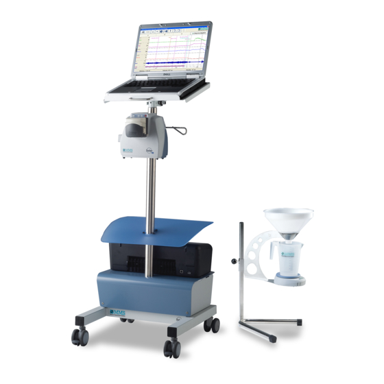
Page 26: Solar Blue On Pole With Integrated Laptop
Solar Blue on Pole with Integrated Laptop The Solar Blue module and a laptop can be mounted on the Solar pole (Ø38mm). LABORIE advises to use a safety module with this setup. Figure 2.4 Solar Blue mounted on pole with integrated laptop The installation procedure is as follows: ... -
Page 27: Safety Module
Safety Module When the complete Solar Blue measurement system is built onto the pole, including the laptop and printer, a safety module may be required. This may also be the case for other set-ups. The module is available for 115V/60Hz and 230V/50Hz @ 300VA. - Page 28 LABORIE if you require these plugs. Power supply cord requirements LABORIE can provide a power supply cord with a European CEE 7/7 or a US / Japan NEMA 5-15 (hospital grade) mains plug. Other types must be purchased locally by an official LABORIE-representative and the cord must comply to all required local standards.
-
Page 29: Pressure Transducer Holder
Different sizes of clamps are available to mount the transducer holder to the Solar pole (Ø38mm) or to the pressure transducer pole (see the Solar Blue Assembly instructions laptop integrated set-up 0075- MAN-099). If necessary, you can change the clamp. -
Page 30: Computer & Laborie Software
Computer & LABORIE Software Introduction The information in this chapter will help you to install the LABORIE software program on the measurement computer. The Solar Blue measurement system is supplied with a Bluetooth wireless interface for communication with the computer. To use the wire-less connection LABORIE has added the Bluetooth dongle for the computer. -
Page 31: Install The Solar Blue Usb Key (If Applicable)
Install the software (see § 3.2). Restart the computer. Connect the Solar Blue USB key to one of the USB ports on the computer or the USB-HUB. Windows will detect new hardware and installation is ready. -
Page 32: Register Bluetooth Devices
You have 15 minutes to register the Bluetooth devices; if needed you can place the batteries again if time has passed. For the Solar Blue module, push the ‘Wake-up’ button on the Solar Blue module shortly. Figure 3.2 ‘Wake-up’ button ... - Page 33 Figure 3.3 Register Bluetooth devices Click the Add button. The window “Add Bluetooth devices” is displayed and the program starts searching for Bluetooth devices. It may take approximately 30 seconds to display the serial number(s) of the applicable module(s) and the Bluetooth sign in this window.
-
Page 34: Hardware Test
Hardware Test 3.5.1 Introduction The Solar Blue hardware test program can be used to perform preventive maintenance on the Solar Blue module and all connected modules (wireless or by USB cables). Information about the connected computer (laptop) can also be found. -
Page 35: Hardware Test (Bluetooth)
Figure 3.6 Solar Blue Hardware test program Bluetooth Click on the module button you want to test (i.e. the Solar Blue module). Further instructions can be found in the following paragraphs: To test the Solar Blue module: see § 4.4. -
Page 36: Hardware Test Solar (Usb)
In the database program, choose Utilities > Hardware test Solar (USB) to test the modules, connected with USB cables. To test the Solar Blue module, make sure that the Solar Blue module is connected to the computer via a USB cable. -
Page 37: Get Usb Information
USB connection to the computer and the power status are graphically displayed. Click the module button you want to test (i.e. the Solar Blue module). Further instructions can be found in the following paragraphs: To test the Solar Blue module: see § 4.4. -
Page 38: Get System Information
Bluetooth. More system information can be found in the Hardware test program (USB). This information can be useful to yourself or your LABORIE representative when you have problems with your system. System information Bluetooth devices In the Hardware test Bluetooth, choose Report > Generate report or click the Bluetooth diagnostic report button to generate the Bluetooth diagnostic report. - Page 39 Figure 3.10 System information Click the button Print system info to select the pages to be printed. Click the Save system info as button to save all system information as RTF file on your hard disk or USB memory stick. The system information consists of the following pages.
-
Page 40: Download Software
3.5.6 Download software The Solar Blue module and most of the other devices are provided with a feature to replace the internal software (firmware), without changing the hardware. This offers the possibility to upgrade the system easily. You can download new software after installing a software upgrade, or when LABORIE provides you with special files. - Page 41 ‘Description’ gives information about the selected file. Select the file to be downloaded and click the Download button. Download software via menu In the hardware test Solar (USB) Choose Software > Download software to display the following window. Figure 3.11 Download software Via this window you can download the software in all connected modules at the same time.
-
Page 42: Troubleshooting
970348<>SN key #@*}))’ is displayed. Check if the software serial number, indicated on the diskette label is the same as your system serial number. If not, contact your LABORIE representative for new software. Check if the USB key is connected to one of the USB inputs on the computer. -
Page 43: Solar Blue Module Does Not Work
Blue module and check if the status indicator on the front lights up shortly. Check if the USB cable is connected between Solar Blue module and computer (in case you use a wired connection). Use another USB connection on the computer. -
Page 44: Wrong Patient Selected
3.6.7 Wrong patient selected The wrong patient was selected when we did the investigation. How can we save the investigation data with the right patient? Cut and paste the investigation data. o Click with the right mouse key in the window ‘Investigations’ on the investigation you want to move. -
Page 45: Maintenance
In this paragraph, you will find cleaning and maintenance instructions for the computer/laptop and peripherals of the Solar Blue measurement system. Cleaning On a monthly base, LABORIE recommends to clean the following parts with a slightly moisturized cloth: outside of the computer, monitor, printer, keyboard and mouse. - Page 46 Perform a functional test on all investigations, available in the measurement program. Check if the investigations starts, if the graphs and results are printed and if the investigation data is saved. Back-up patient data It is important to make a back-up of your patient data regularly, to prevent losing data because of a computer crash.
- Page 47 © 2008 – 2020 by MMS B.V. Chapter 3...
-
Page 48: Solar Blue Module
The Solar Blue module is powered by its power supply. The pump unit is integrated in the Solar Blue module. The pump can be used to fill the bladder with saline during urodynamic investigations. A pump tube is connected to a bag of saline and positioned in the pump. -
Page 49: Installation
Installation 4.2.1 Install the Solar Blue module In this paragraph, you will all the information to install the Solar Blue module and to connect catheters, pump tubes and EMG cables. To install the Solar Blue module, proceed as follows: Install the pump head (see § 4.2.2). -
Page 50: Install The Pump Head
4.2.2 Install the pump head To prevent damaging during transport, the Solar Blue module will be delivered with the pump head separated. Attach the pump head to the Solar Blue module as follows: Remove any protection label on the shaft entry of the pump head. Please note that the entry is greased. -
Page 51: Connect The Power Adapter
Release the pump head. 4.2.3 Connect the power adapter The medical grade power adapter can be used to power the Solar Blue module. During an investigation. Solar Blue adapter receptacle This receptacle is used to connect the dedicated medical grade power supply for the Solar Blue module\. -
Page 52: Usb Interface
Doing so may cause fire leading to serious accidents. The Status LED will be green. The Battery LED is unlit. The DC receptacle on the Solar Blue module should be kept clean for optimal performance. 4.2.4 USB interface The USB interface is used to connect the Solar Blue module to the computer via a USB cable. -
Page 53: Control Panel
Figure 4.7 Connect the Solar Blue module directly to the computer 4.2.5 Control panel The control panel is used to indicate the status of the Solar Blue module. The control panel contains: the status LED [1], the battery LED [2], the Bluetooth LED [3] and the infrared receiver [4]. -
Page 54: Mms-Bus Receptacles
Puller (wired). The MMS-bus receptacles can only be used when the Solar Blue module is connected to the computer via a USB cable and when the Solar Blue module is powered by the power supply. Figure 4.9 MMS-bus receptacles 4.2.7... - Page 55 XX, DT-NN or Sensonor/Memscap) you need a transducer holder mounted on a pole (see also § 2.8). With DT-XX or DT-NN pressure transducers you need interface cables to connect the transducers to the Solar Blue module. Figure 4.11 Transducer holder pole for water transducers ©...
-
Page 56: Emg Connection
4.2.8 EMG connection The Solar Blue module is equipped with one EMG input (DIN-5). Figure 4.12 EMG input EMG cables and electrodes The following types of EMG cables/leads and electrodes are recommended to use with the Solar Blue module: EMGC-D5-SUR (= guarded EMG cable with DIN-5 connector and integrated DIN 42 802 and 3 electrodes with press studs, 180 cm). -
Page 57: Install The Pump Tube
The pump has four rollers and the rotation direction is predetermined counter- clockwise. The rotation and flow direction is indicated by the arrow label on top of the pump. Figure 4.16 Pump of the Solar Blue Figure 4.17 Flow direction module ©... - Page 58 Use only sterile filling liquids and sterile pump tubes from LABORIE (code: OBS 275/C or 275/D) for the pump module. Proper operation of the Solar Blue is not guaranteed when using other brands and/or types of pump tubes. It is important to place the pump tube correctly and to replace the pump tube after each investigation to maintain a yield accuracy within a 10% window.
-
Page 59: Block Diagram
Block Diagram The figure below shows the block diagram of the Solar Blue module. Figure 4.18 Block diagram Solar Blue module © 2008 – 2020 by MMS B.V. Chapter 4... -
Page 60: Hardware Test
Hardware Test 4.4.1 Introduction The Solar Blue module can be tested in the hardware test program Bluetooth. Choose Utilities > Hardware test Bluetooth to start the hardware test program. Click on the Solar Blue module button to show the following window. -
Page 61: Pump Test
4.4.2 Pump Test Choose the TAB Pump to test the pump of the Solar Blue module. Figure 4.20 Pump test The procedure is as follows: Hang a bag (or bottle) of saline on the hook. Install a pump tube in the pump. - Page 62 Solar Blue module. Pump calibration LABORIE advises NOT to calibrate the pump when the pump is performing well within acceptable ranges. When the pump performance deviates we recommend to find the cause of the problem first, for example the filling lumen of the catheter is blocked, the spike is not pushed all the way into the bag or a non-specified pump tube is used.
-
Page 63: Pressure Test
Connect the flowmeter via a wired connection to an MMS-bus receptacle (when the hardware test Solar (USB) is used). Make sure the power adapter is connected to the Solar Blue module in this case. Place the catheter in the water container which is positioned on the flowsensor. - Page 64 The easiest way to do this is using a water-column of at least 100 cm. The procedure is as follows: Connect the catheter(s) to the connectors of the Solar Blue module. Click the Zero all button to zero all channels at atmospheric pressure simultaneously.
- Page 65 O ± deviation of catheter ± 2 cmH O ± deviation of catheter You can also test all transducers connected to the Solar Blue module, a selection of these transducers, or the complete catheter with all transducers based on a catheter definition.
-
Page 66: Emg Test
4.4.4 EMG test Choose the TAB Pressures / EMG to test the EMG of the Solar Blue module. Figure 4.22 Test the EMG signal The procedure is as follows: Stick EMG electrodes on your arm as shown in figure. -
Page 67: Remote Control Test
4.4.5 Remote control test Choose the TAB Test remote control unit to test the remote control. Figure 4.24 Test the remote control For more information, see § 5.3. © 2008 – 2020 by MMS B.V. Chapter 4... -
Page 68: Hardware Status
Click the Packet info button to display module information about the received and missed packets, and the selected and effective sample rate. Click on the Reset to factory defaults button to reset the following Solar Blue data to factory defaults: ... -
Page 69: Troubleshooting
Troubleshooting 4.5.1 Registering Bluetooth Solar Blue is not possible The menu item ‘Register Bluetooth devices’ is not available. Contact your LABORIE representative. © 2008 – 2020 by MMS B.V. Chapter 4... -
Page 70: Solar Blue Module Not Displayed In Hw Test Program
4.5.2 Solar Blue module not displayed in HW test program The Solar Blue module is not displayed in the hardware test program (§ 4.4). In case you use the hardware test program Bluetooth: Register the Solar Blue module in the hardware test program Bluetooth (§... -
Page 71: Pressure Channel Is Not Displayed
Most probably the pressure channel was not properly zeroed. Connect another Lemo 4 connector of a solid-state catheter. Check if something is wrong with the catheter or the Solar Blue interface. Connect the air charged catheter to another pressure transducer. Check if something is wrong with the transducer/catheter or the Solar Blue interface. -
Page 72: Question Marks On Pressure Channel
Check if one of the cables, plugs or connectors is damaged. A damaged cable or connector can be repaired. Try another set of EMG electrodes. Place the Solar Blue module at another position. Other equipment may cause noise on your EMG signal. Contact your LABORIE representative. -
Page 73: Cleaning And Maintenance
The urine container and the funnel should be rinsed with water and cleaned with detergent. Remove water from the flowsensor and the flow stand with a soft, dry cloth. Remove water from the Solar Blue module, Solar pole and its devices with a soft, dry cloth. NOTE For cleaning and sterilization of the catheters or accessories (e.g. - Page 74 Check all devices (modules) on availability. You can use the graphic representation in the hardware test (see § 4.4). Test the infrared receiver and the remote control with the hardware test (see § 4.4 and § 5.3). Pump. The moving parts of the rotor should be checked from time to time for freedom of movement.
- Page 75 © 2008 – 2020 by MMS B.V. Chapter 4...
-
Page 76: Remote Control
The RC-1200 remote control can be used to perform investigations with the Solar Blue measurement system. The RC-1200 transmits infrared signals (invisible), so no cable is required. The Solar Blue module is standard equipped with an infrared receiver (see chapter 4 for more detailed information). -
Page 77: Install The Battery
The remote control is powered by one button cell battery CR2025. Replace the battery at least every 6 months to avoid leakage. The operational distance between remote control and Solar Blue measurement system will decrease if battery power is low. - Page 78 Figure 5.4 Position thumb nail (1) and finger nail (2) Insert the new battery in the compartment as shown in the pictures below (the battery fits in only one way). Figure 5.5 Insert battery in compartment Insert the battery compartment in the remote control as shown in the pictures above.
-
Page 79: Hardware Test
There are two ways to start the remote-control unit test: Choose Utilities > Hardware test Bluetooth to start the hardware test program. Click on the Solar Blue module button and choose the TAB Remote control unit to perform the test. -
Page 80: Troubleshooting
If it functions correctly, the key probably has no function in the investigation being performed. Check if the green status LED at the front of the Solar Blue module is on. If this is not on, consult trouble shooting of the Solar Blue module. - Page 81 © 2008 – 2020 by MMS B.V. Chapter 5...
-
Page 82: Bluetooth Flowmeter (Mk Iii)
The flowmeter is powered by four batteries (type AA Alkaline 1.5 Volt or NiMH 1,2 Volt) or by an optional wall-cube power adapter. It is always possible to connect the Bluetooth flowmeter to the Solar Blue module by using a digital MMS-bus cable. Three conditions must be met: ... -
Page 83: Installation
The Bluetooth flowmeter is supplied with flowsensor, stand, funnel and urine container as displayed below. The Bluetooth flowmeter only works when the LABORIE software with Bluetooth functionality has been installed on your computer (see § 3.2). In the figure below, the flowmeter and its parts are illustrated. - Page 84 the Solar Blue module needs to communicate with the computer via USB, the Solar Blue module must be powered by the external power supply, and the flowsensor must be connected to one of the digital MMS-bus ports of the Solar Blue module (note: it is not possible to connect the power adapter to the flowsensor as it is powered by the Solar Blue external power supply).
- Page 85 Connect the Solar Blue module directly to a USB connection on the computer, not via a USB-HUB. Figure 6.3 Connect the Solar Blue module directly to the computer Pick-up the flow stand The best way to pick-up the flow stand is to take the flow stand arm on which the funnel is placed.
-
Page 86: Status Led
The Bluetooth flowsensor contains one LED for Bluetooth and Status indication. In the table below you will find a description. Indication Orange On IPL error. Contact your LABORIE representative. Green On Digital cable is connected. Green blinking Bluetooth communication flowsensor powered by (short periods off) power adapter. -
Page 87: Protocol Settings
Select the investigation in which the flowmeter is being used, e.g. uroflow or pressure-flow study. Figure 6.5 Edit protocol Click the Connections button. Default the Solar Blue measurement system will use all connected or registered flowmeter(s) with the ‘automatic selection’ setting. You can also select one specific flowmeter. When the flowmeter is not used for a specific measurement (i.e. -
Page 88: Test The Bluetooth Flowmeter
The procedure is as follows: Double-click on the LABORIE Database button. Click on the New investigation button. Select one investigation in which the Bluetooth flowmeter is enabled. The pre-test of the investigation is started and the computer establishes a wireless connection with the Bluetooth flowmeter. -
Page 89: Block Diagram
The MMS-bus interface is used for the wired data and power connection with Solar Blue module. The MMS-bus interface socket can also be used for an external power adapter (Bluetooth module only). Standard for the Bluetooth flowmeter, the housing provides a small drawer for four AA type batteries. With this amount of batteries, the flowmeter will last one month under normal conditions. -
Page 90: Hardware Test
When nothing is placed on the flowsensor, the readout of the field “Weight absolute” on the screen should be less than 500 grams. If this is not the case, contact your LABORIE representative. © 2008 – 2020 by MMS B.V. - Page 91 the Solar Blue module is connected to the computer via a USB cable, the flowsensor is connected to the Solar Blue module with a digital cable to one of the digital MMS-bus ports of the Solar Blue module, and ...
-
Page 92: Troubleshooting
Troubleshooting 6.5.1 Registering Bluetooth Flowmeter is not available The menu item ‘Register Bluetooth devices’ is not available. Contact your LABORIE representative. © 2008 – 2020 by MMS B.V. -
Page 93: Flowmeter Not Displayed In Hw Test Program
Register the flowmeter in the hardware test program Bluetooth (§ 3.5.2). In case you use the hardware test program (USB): Check if the power adapter is connected to the Solar Blue module. Check if the MMS-bus cable is connected between Solar Blue module and the flowmeter. -
Page 94: Generated Values Are Too Low
500, when no weight is on the sensor, the offset is too high. Contact your LABORIE representative. If the offset value is smaller than 500, the hexagonal bold in the load-cell is turned too far to the outside. Contact your LABORIE representative. 6.5.5 Values are not within limits ... -
Page 95: Cleaning And Maintenance
Maintenance LABORIE advises to perform preventive maintenance at least once a year. Test the Bluetooth flowmeter Mk III with the hardware test program (see § 6.4). When malfunctions are found during the test procedures, refer to § 6.5 Trouble shooting to fix the module. -
Page 96: Bluetooth Puller (Mk Iii)
Bluetooth Puller (Mk III) Introduction The Bluetooth Puller Mk III can be used to make pressure profiles of the urethra. For this purpose, a pressure measuring catheter is inserted into the orifice and retracted with a predetermined speed and/or over a predetermined distance by the puller. -
Page 97: Installation
7.2.1 Install the Bluetooth puller The Bluetooth puller can be assembled on the Solar Blue pole Mk III wheelbase, the separate puller wheelbase or the Solar Maquet chair. In the figure below, the puller and its parts are illustrated. The puller is standard supplied with a carrying arm (not illustrated). - Page 98 A silicone disk is compressed around the slider to prevent the main part of any liquid pollution from entering the slider opening in the puller enclosure. The slider opening in the enclosure is a tight-fitting confinement around the slider to provide good alignment and a guiding conduit.
-
Page 99: Control Panel
Various sliders and guiders To prevent contamination and to shorten the time between patients, LABORIE advises to use various sets of catheter sliders and guiders. These parts can be replaced quickly and easily. Cleaning instructions can be found in § 7.6. - Page 100 Orange on IPL mode and/or downloading firmware. Red on The puller has detected an internal failure. Contact your LABORIE representative. Battery Green on The rechargeable batteries are fully charged. Green blinking The power adapter is connected to the puller (and charging the batteries).
-
Page 101: Install The Batteries
7.2.3 Install the batteries The Bluetooth puller is supplied with four NiMH AA rechargeable batteries (≥ 2300 mAh) batteries. These batteries must be installed in the battery compartment and charged with the power adapter. The procedure is as follows: Remove the two screws of the battery compartment (see figure 7.2/[3]) with a 3 mm Allen key. -
Page 102: Connect The Power Adapter
Replacement of the batteries LABORIE advises to replace the four rechargeable batteries with new ones at least once every two years, or when the performance is getting low. Always replace all batteries at the same time, with rechargeable NiMH AA batteries of the same brand, type and capacity (≥... -
Page 103: Protocol Settings
7.2.5 Protocol settings The software program contains one investigation protocol in which you can enable the Bluetooth puller for each investigation type separately. Also, puller related settings as puller speed can be set. The procedure is as follows: In the measurement program, click with the right mouse button on one of the protocols and choose Edit protocol. -
Page 104: Test The Bluetooth Puller
The procedure is as follows: Double-click on the LABORIE Database button. Click on the New investigation button. Select one investigation in which the Bluetooth puller is enabled. The pre- test of the investigation is started and the computer establishes a wireless connection with the Bluetooth puller. - Page 105 Figure 7.6 Puller buttons In the top of the screen, the puller buttons are displayed as an indication that the puller module is functioning. The Status and Battery LED’s are on and the Bluetooth LED is blinking. Consult trouble shooting if the puller is not found (see § 7.5). ...
-
Page 106: Block Diagram
Block Diagram The figure below shows the block diagram of the Bluetooth puller Mk III. Figure 7.7 Block diagram Bluetooth puller The principle of the Bluetooth catheter with slider (toothed bar) requires a stepper motor. This ensures free movement of the slider when no current to the motor is applied. - Page 107 The 12V power supply is required for supplying the power for the motor driver’s power bridge. The battery voltage (3,6 … 6V) is converted by a step- up converter to 12V. It is controlled by the micro controller and only switched on when the motor current is required.
-
Page 108: Hardware Test
Hardware Test The Bluetooth puller can be tested in the hardware test program Bluetooth. Choose Utilities > Hardware test Bluetooth to start the hardware test program. Switch on the Bluetooth functionality: press the Unlock slider button on the control panel of the puller until the blue light lights up shortly. In the hardware test program, click on the Bluetooth puller module button to display the following window. - Page 109 Over a distance of 100 mm, the measured puller distance may deviate 2 mm (+ maximum clearance of the puller block). When the deviation is more, the puller must be sent to LABORIE for repair. Puller speed The puller speed can be set in the window. During the test the speed can be changed by selecting another speed.
-
Page 110: Trouble Shooting
You must solve the problem and to repeat the investigation. The LABORIE software cannot recognize this situation nor compensate it during the analysis. © 2008 – 2020 by MMS B.V. -
Page 111: The Slider Makes A Rattling/Ticking Sound
The slider is blocked (cannot move freely). Clean and reposition the slider. You can also clean and check the functioning of the pinion. The slider is damaged, try another slider. Contact your LABORIE representative. 7.5.5 The slider makes a rattling/ticking sound The slider makes a rattling/ticking sound. -
Page 112: Battery Led Is Blinking
Contact your LABORIE representative. 7.5.8 Battery LED is blinking The Battery LED is blinking orange or red, but the power adapter is not connected. Connect the power adapter (charge the batteries). Replace the batteries. Contact your LABORIE representative. -
Page 113: The Puller Battery Is Depleted
7.5.12 The puller battery is depleted The puller has stopped and the message ‘Puller has stopped. Puller battery is depleted’ is displayed during the pre-test or the investigation. The batteries are depleted. Connect the power adapter and charge the batteries. -
Page 114: No Bluetooth Connection And The Bluetooth Led Is Off
Removing this part gives access to the plastic pinion that drives the slider. This pinion is limited in torque and poses no threat to fingers or other body parts. LABORIE recommends to clean the following parts: On a daily base, low level dis-infect the slider and the guider in an instrument (medical) dishwasher with a maximum temperature of 80 °C... - Page 115 LABORIE representative. Some mechanical parts need to be replaced after intensive use, for example the plastic pinion and the slider and its parts. Contact your LABORIE representative for more information. The catheter clamp on the slider contains a small piece of silicon rubber which is necessary to clamp and slide the catheter.
-
Page 116: Luna Wireless Module
Safety Information In this paragraph, you will find safety information for the Luna as part of the Solar Blue measurement system. For safety information about the Luna standalone system see the Luna User’s & Service Manual (document code: 0075-MAN-032). - Page 117 interference that may cause undesired operation. This device contains WML- C40, with FCC-ID POOWML-C40. WARNING The patient connections of the Luna system are body floating. When the system is connected to a computer, make sure that the requirements of the IEC 60601-1 are met: (1) the computer must conform to IEC 60950, UL 950 or IEC 60601, and (2) the enclosure leakage current of the computer (and USB connector) must be limited in...
-
Page 118: Installation
Installation 8.3.1 Install the Luna wireless module The Luna is supplied with a Bluetooth wireless interface for communication with the computer. Only one BT dongle is needed to use the Bluetooth devices (Luna module, Bluetooth flowmeter and/or Bluetooth puller). For installation of the software with Bluetooth, see chapter 3. After installation of the software you must register the Luna as described in §... -
Page 119: Install The Battery
8.3.2 Install the battery The Luna needs one battery type AA alkaline (1.5 Volt). Figure 8.3 Battery compartment Remove the cover [1] of the Luna battery compartment [2] and insert the battery as displayed in the figure above. During stationary measurement, the software displays a message to change battery when necessary. -
Page 120: Set The Investigation Protocol
8.3.3 Set the investigation protocol In the protocol settings of the stationary measurement program you will find the channel configuration by clicking on the Connections button. The channel names will pre-fixed by the Luna module. The default settings are: Pves (1) = Luna P1 Pabd (2) = Luna P2... -
Page 121: Connect Emg
8.3.5 Connect EMG The Lemo 3 plug must be connected to the EMG input on the Luna. It is possible to measure EMG using surface electrodes. EMG cable and electrodes The recommended EMG cable to use with the Luna is the UD 597 A6 (= guarded EMG cable for 3 surface electrodes with press studs, 60 cm). -
Page 122: Block Diagram
Block Diagram The figure below shows the block diagram of the Luna wireless Module. Flowsensor LEMO-5 RS485 (no USB) connector interface 2500V supp. insulation Conductance LEMO-3 (max 2 ch.) connector Pressure To PC interface LEMO-4/6 conn. (max 2 ch.) connector Pressure LEMO-4/6 (max 2 ch.) - Page 123 Figure 8.6 Test Luna Test pressure channels and solid state catheters The easiest way to test the Luna and the catheters (solid state or air charged) is by using a water-column of at least 100 cm. The procedure is as follows: ...
- Page 124 The measured volume may deviate as follows (when the measured values are not within the allowed limits, you can clean the catheter or calibrate the transducers). Applied pressure (cmH Allowed limits (cmH ± 2 cmH O ± deviation of catheter ±...
-
Page 125: Troubleshooting
The Register Bluetooth and Select Luna dialog does not appear Enable the Bluetooth devices in the system settings of the measurement program. If this option is not available in the system settings, contact your LABORIE representative. The Bluetooth connection is not working ... -
Page 126: Technical Specifications
Technical Specifications Solar Blue module Solar Blue module: Pump, Pressure interface, EMG interface Software Uroflowmetry. Cystometry. Pressure-flow study. Urethral Pressure Profile UPP (optional). Gynecology study / Combination study (optional). EMG (optional). Anorectal manometry (optional) ... - Page 127 General Applied part class: BF. Degree of ingress protection: IPX1. Dimensions: 195 x 195 x 155 mm (l x w x h), no clamp. Weight: o approximately 2,5 kg Mounting possibilities: o Rail 25x10 o Pole 20 - 40 mm o Table top ...
- Page 128 Pressure Interface Number of channels: 4. Input for solid state (microtip), air-charged transducers (catheters), Memscap and Argon (formerly B-D) DT-XX transducers (water catheters). Measured channels: P , and P Calculated channels: P and P clos Pressure range: -650 ... + 1200 cmH ...
-
Page 129: Solar Pole
IR receiver Receiving distance: at least 4m. Receiving angle: 30 degrees in respect to focus center line. Solar Blue power supply Type: PS-SBL, 25W, medical grade. Isolation class: Class II. Output voltage: 15 Vdc (SELV). - Page 130 Length: 85 cm (34”). Diameter: 38 mm (1,5”). Material: Stainless Steel. Weight: approximately 3 kg. Hook integrated in Solar Blue clamp. Laptop shelf pivot on top of pole Base box Material: Steel, powder coated.
-
Page 131: Safety Module
Safety Module Power rating: 300VA Nominal voltage: 115V/60Hz or 230V/50Hz On / Off switch Isolation class: Class I AC outlets: 4 x C13 sockets AC input: C14 socket Safety earth point: 1x M6 thread stud ... - Page 132 Flow stand Material: stainless steel (AISI304). Adjustable: 37 cm – 83 cm. Dimensions: 545 (710) x 365 x 360 mm (h x w x d). Weight: 2.5 kg. Funnel Material: HDPE (high density polyethylene). Diameter: 262 mm. Urine container ...
-
Page 133: Bluetooth Puller (Mk Iii)
Power supply (optional) Type: F3BT-PS, 12W, medical grade. Isolation class: Class II. Output voltage: 5 Vdc (SELV). Mains voltage: 100 – 240Vac, 50/60Hz. DC cable length: 1,8m. Bluetooth Puller (Mk III) General Applied part: type B. ... -
Page 134: Remote Control (Rc-1200)
Power supply (charger) Type: PS-BT-PULLER, 12W, medical grade. Isolation class: Class II. Output voltage: 7,5 Vdc (SELV). Mains voltage: 100 – 240Vac, 50/60Hz. DC cable length: 1,8m. Wireless connection Technology: Bluetooth. Range: 50 m (free air, good conditions). ... -
Page 135: Luna Wireless Module
Luna Wireless Module Applied part: type BF. Degree of ingress protection: IP2X. General Pressure channels (2 to 3), EMG, Conductance (optional). Sampling rate: user selectable at 1, 2, 4 or 8 samples per second (Hz) Battery type: one AA alkaline (1.5 Volt) or NiMH battery. ... -
Page 136: Computer Requirements
Cable length EMG: < 3 meter. Signal representation Mean rectified. Computer Requirements The computer connected to the Solar Blue measurement system must comply with the IEC 60950 and/or UL 1950. The minimum computer requirements for the Windows software for the Solar Blue system are: ... - Page 137 Hard disk: 500 GB. DVD-RW. Soundcard/speakers. 4 to 7 USB ports (Solar Blue module, USB protection key, keyboard, mouse, printer). Possible USB additions: Bluetooth dongle, memory stick. 17 inch color monitor. 2 button mouse.
- Page 138 APPENDICI, WARRANTY AND INDEX © 2008 – 2020 by MMS B.V.
- Page 139 © 2008 – 2020 by MMS B.V.
-
Page 140: Appendix A Safety Information
Blue measurement system can be found in the Solar Blue User’s Manual (Document Code: 0075-MAN-093-EN). The Solar Blue measurement system is a prescription device to be used only by physicians or individuals who have been trained and authorized by a physician or by a medical institution, under the supervision of a physician. - Page 141 The instructions and warnings in this manual should be followed by the operator to ensure safe operation and to maintain the Solar Blue measurement system in a safe condition. Therefore, the use of the Solar Blue measurement system should be restricted to qualified personnel only.
- Page 142 Before taking the system into operation, the system must be allowed to acclimatize to the specified operating conditions for at least 4 hours. All repairs, which are not performed by LABORIE are for the responsibility of the hospital. LABORIE will not give any guarantee or take any responsibility for any part which has been opened, adjusted or replaced by hospital personnel.
- Page 143 WARNING Connect only LABORIE devices to the Solar Blue measurement system (except computer and catheters). WARNING Safety can be violated if the Solar Blue measurement system or one of its modules shows visible damage. WARNING Do not attempt to open any modules.
- Page 144 CAUTION If one or two devices are connected to the Solar Blue MMS-bus connections, two conditions must be met: the Solar Blue module is connected to the computer with the USB cable (the Solar Blue module communicates via USB with the computer), ...
- Page 145 WARNING To ensure stability and safety, do not mount/attach other devices to the Solar pole then laptop, Solar Blue module, pressure transducer frame and holder, bag of saline (for infusion via pump), bag of saline and pressure-cuff (for perfusion of Pura).
- Page 146 IEC 60950, EN 60950 or UL 60950. WARNING The printer may not be connected (wired) to a computer without a safety module when the Solar Blue module is connected to the PC via USB. Preferably use a wireless printer.
- Page 147 WARNING Only connect items that have been specified as part of the system or that have been specified as being compatible with the Solar Blue system into the Safety Module. By plugging in unapproved items the level of safety may be...
- Page 148 Solar Blue Module The Solar Blue module complies with Part 15 of the FCC Rules. Operation is subject to the following two conditions: (1) this device may not cause harmful interference, and (2) this device must accept any interference received, including interference that may cause undesired operation.
- Page 149 Leave the system completely in rest. Disturbance will cause a wrong calibration! CAUTION Make sure that the infrared receiver on the Solar Blue module (red circle on the user interface) is always visible. CAUTION Make sure to support the Solar Blue module when adjusting its position on the pole, because the Solar Blue module can weigh more than three kilos.
- Page 150 Luna Wireless Module The Luna complies with part 15 of the FCC Rules. Operation is subject to the following two conditions: (1) this device may not cause harmful interference, and (2) this device must accept any interference received, including interference that may cause undesired operation. This device contains WML- C40, with POOWML-C40.
- Page 151 CAUTION Do not drop or throw the flowsensor. Do not apply excessive force on the flowsensor (maximum 3.5 kg) or let things drop on the flowsensor. This can permanently damage the flowsensor. CAUTION Avoid touching or kicking the flowsensor during an investigation.
- Page 152 WARNING When adjusting the spring-balanced arm be aware not to pinch fingers or other objects. WARNING Connect the power adapter whenever the Bluetooth puller is not used to prevent batteries to become depleted. Deep discharging the batteries will damage the batteries internally and shorten the lifespan.
- Page 153 (e.g. EMG needle electrodes), see the manufacturer’s instructions. Investigations WARNING Investigation procedures as described in the Solar Blue manuals do not pretend to be complete. How an investigation is performed and how the results are interpreted, the actual diagnosing, remains under all circumstances the responsibility of the clinician/physician performing the investigation.
- Page 154 Do not use excessive amounts of water for cleaning the Solar Blue measurement system to prevent damaging the electronics. CAUTION Never allow water to get inside the Solar Blue modules or any other part to prevent damage to the system. © 2008 – 2020 by MMS B.V. Safety Information...
- Page 155 Be sure to perform a safety test in accordance to IEC 60601-1 after modules/devices have been replaced or opened. WARNING Before repair make sure that the Solar Blue measurement system is switched off and disconnected from the mains. CAUTION Before repair always take antistatic precautions.
- Page 156 Safety Regulations Module Protection Class Applied Ingress (depending on setup) part protection rate Solar Blue Class II IPX1 Luna wireless IP2X module Bluetooth flowmeter Class II if powered by IPX1 (Mk III) power adapter Safety module Class I IP20 Bluetooth (wireless)
- Page 157 © 2008 – 2020 by MMS B.V. Appendix A...
-
Page 158: Appendix B Explanation Of Symbols
Appendix B Explanation of Symbols This appendix gives explanation of the symbols on the Solar Blue system Follow instructions for use. Blue symbol Consult operating instructions. Caution: Federal law restricts this device to sale by or on the order of a physician Triangle with black or red border: Caution, consult instructions for use. - Page 159 Type BF applied part conform IEC 60601-1. Protected against solid foreign objects of 12,5 mm Ø and IP20 greater and not protected against liquids. The pouch provides protection against ingress of dripping water IPX2 with harmful effects when tilted 15°. Protected against dripping water.
- Page 160 CE (93/42/ EEC) approved. Nationally Recognized Testing Laboratories Never put fingers or any other body parts in the pump while it is running. Symbol with red border Double insulated conform IEC 60601-1. Atmospheric pressure range 700 hPa to 1060 hPa. Operating Conditions: Temperature range +15°C to + 35°C.
- Page 161 This device uses a RF transceiver for data transfer purposes. This product is subject to WEEE directive 2012/19/EU. Contact your local authority for information about disposal and recycling. The weight of the Solar Blue module is 3,5 kg. © 2008 – 2020 by MMS B.V. Appendix B...
- Page 162 Energy source. Do not push or pull. Symbol with red border Manufacturer. May be combined with manufacturing date. Mass (including safe working load) in kilograms. Catalogue number. Serial number. Quantity symbol: Numeral in symbol (in place of #) indicates the quantity of units in package. ©...
- Page 163 Explanation of PE-number PEYY-FXXXXNNNN Peripheral Equipment 2 digit manufacturing year number Product group number XXXX 3 or 4 digit unique module abbreviation NNNN 4 digit incrementing unique number Explanation of SN-number SN YYXXNNNN Serial Number 2 digit manufacturing year number 1 or 2 digit product identification number NNNN 4 digit incrementing unique number...
-
Page 164: Appendix C Explanation Of Terms
Dedicated MMS-bus cable. MMS-Bus Dedicated software and hardware protocol for communication between investigation modules. Pressure Simulator Device to test the Solar Blue module with Lemo 4 connectors. RC-1200 Remote control. Solar Blue Module Main module with integrated pump, 4x pressure connectors, 1x EMG connector, 1x infrared receiver, 1x USB connector and 2x MMS-Bus. - Page 165 © 2008 – 2020 by MMS B.V. Appendix C...
-
Page 166: Appendix D Electro Magnetic Compatibility
The equipment should be visually inspected regularly for damaged cables and connectors. Damaged cables should be replaced. If the Solar Blue system is used in a location near (e.g. less than 1,5 km from) AM, FM or TV broadcast antennas, it may be necessary to take preventive actions for reducing the EM interfering level (for instance by shielding the investigation room). - Page 167 Guidance and manufacturer’s declaration – electromagnetic emissions The Solar Blue measurement system is intended for use in the electromagnetic environment specified below. The customer or the user of the Solar Blue measurement system should assure that it is used in such an environment.
- Page 168 WARNING When the Solar Blue is used adjacent to or stacked with other equipment its normal operation should be verified. Guidance and manufacturer’s declaration – electromagnetic immunity The Solar Blue measurement system is intended for use in the electromagnetic environment specified below. The customer or the user of the Solar Blue measurement system should assure that it is used in such an environment.
- Page 169 0 % U 70 % U (100 % dip in U ) (30 % dip in U ) for 5 sec for 25 cycles 0 % U (100 % dip in U ) for 5 sec Power 30 A/m 30 A/m...
- Page 170 Guidance and manufacturer’s declaration – electromagnetic immunity The Solar Blue measurement system is intended for use in the electromagnetic environment specified below. The customer or the user of the Solar Blue measurement system should assure that it is used in such an environment.
- Page 171 If the measured field strength in the location in which the Solar Blue is used exceeds the applicable RF compliance level above, the Solar Blue should be observed to verify normal operation. If abnormal performance is observed, additional measures may be necessary, such as reorienting or relocating the Solar Blue.
- Page 172 WARNING: Portable RF communications equipment (including peripherals such as antenna cables and external antennas) should be used no closer than 30 cm (12 inches) to any part of the Solar Blue system, including cables specified by the manufacturer. Otherwise, degradation of the performance of this equipment could result.
- Page 173 © 2008 – 2020 by MMS B.V. Appendix D...
-
Page 174: Appendix E Solar Blue Safety Barriers
Appendix E Solar Blue Safety Barriers © 2008 – 2020 by MMS B.V. - Page 175 © 2008 – 2020 by MMS B.V. Appendix E...
-
Page 176: Appendix F Software Messages
Software messages measurement and analysis Message Cause Posible actions to resolve An error occurred related to the video digitizer! Error with video digitizer Contact your LABORIE Video will be disabled. representative Blood pressure meter not active. Retry to Module not active Retry connecting connect? Bluetooth flowmeter connection lost. - Page 177 The Solar Blue is powered via the power adapter. The Solar Blue is connected to the computer via USB. Digital Puller not connected! To use the manual...
- Page 178 The Solar Blue is powered via the power adapter. The Solar Blue is connected to the computer via USB. DT-XX transducer not connected to CO2 module...
- Page 179 Message Cause Posible actions to resolve representative Luna EMG not present Luna channel expected but not Contact your LABORIE present representative Luna P1 not present Luna channel expected but not Contact your LABORIE present representative Luna P2 not present Luna channel expected but not...
- Page 180 This firmware is not available on your representative computer. Please contact your dealer. The Solar Blue is connected to the computer via Solar Blue is connected via USB Contact your LABORIE USB but not all MMS bus ports were recognized...
- Page 181 System is not powered Connect the power power connection The WPU [Name] has lost the connection Communication problems Contact your LABORIE representative There are more channels available in the Protocol file comes from a later Install correct software protocol file ([Filename]) then supported by this...
- Page 182 Creating a backup also failed. All changes Failed to create a backup Contact your LABORIE made have gone lost. Contact your representative administrator. Creating safety backup failed! Safety backup could not be...
- Page 183 Message Cause Posible actions to resolve File not found. Restore of patient aborted FCU file is incomplete Contact your LABORIE representative General database error, back-up failed! Database could not be Try again later or openend contact your LABORIE representative HIS interface module not initialized...
- Page 184 Message Cause Posible actions to resolve available representative Storage failure. Error in FCU file FCU file is corrupted Contact your LABORIE representative System number is empty. Archive of patient Patient system number is Contact your LABORIE aborted representative empty System number is incorrect. Archive of...
- Page 185 Solar Blue is connected via bluetooth, USB Communication problems Contact your LABORIE communication is disabled representative Solar Blue is not found. Please check the Communication problems Contact your LABORIE USB and power connection representative Solar Blue is not powered. Please check the...
-
Page 186: Warranty For Solar Blue System
Solar Blue, are responsible for keeping current with developments in the literature on uro- dynamics or gastro-enterology. Please direct any questions or problems concerning uro-dynamics or gastro- enterology and the use of the instrument, or interpretation of data acquired from the Solar Blue to the responsible physician(s). - Page 187 Registration Card to MMS. 8. MISCELLANEOUS. This Licence shall be governed and construed in accordance with the laws of the Netherlands and shall benefit MMS, its successors and assigns. © 2008 – 2020 by MMS B.V. Warranty for Solar Blue System...
- Page 188 BETWEEN THE PARTIES AND SUPERSEDE ALL PROPOSAL OR PRIOR AGREEMENTS, ORAL OR WRITTEN, AND ANY OTHER COMMUNICATIONS BETWEEN PARTIES RELATING TO THE SUBJECT MATTER OF THE LICENCE OR THE LIMITED WARRANTY. © 2008 – 2020 by MMS B.V. Warranty for Solar Blue System...
- Page 189 © 2008 – 2020 by MMS B.V. Warranty for Solar Blue System...
-
Page 190: Index
Bluetooth puller ........................ 95, 100, 101 Flowmeter Mk III ........................81, 82 Luna wireless module ......................118, 134 remote control ........................... 76 status Solar Blue module........................67 Block diagram Bluetooth puller ..........................105 Flowmeter Mk III ..........................88 Solar Blue module ..........................58 Bluetooth dongle ........................... - Page 191 Cleaning Bluetooth Flowmeter Mk III ......................94 Bluetooth puller ..........................113 catheter .............................. 72 computer ............................44 Solar Blue measurement system ....................... 12 Solar Blue module ..........................72 Combination Interface Module block diagram ..........................121 Computer download software ..........................39 hardware test .............................
- Page 192 Database program ..........................13 Diagnostice program ..................... See hardware test Dimensions Solar Blue ........................126 Download software..........................39 connection (Solar Blue module) ....................... 55 EMG cable CIM ..............................55 color coding ............................ 120 Luna wireless module ........................120 EMG connector Luna wireless module ........................
- Page 193 ............................44 pressure connectors ........................... 63 pump (Solar Blue module) ........................ 61 remote control ........................... 79 Solar Blue measurement system ................... 11, 33, 44 Solar Blue module ..........................72 Manual ..............................14 Manual conventions ..........................15 Manual Feedback ..........................17 Measurement program ...........................
- Page 194 introduction ............................29 trouble shooting ..........................41 Operating system ........................... 10 Patient archive patient data ........................... 45 back-up patient data .......................... 45 Pressure connections ..........................53 Pressure transducer air-charged ..........................22, 47, 53 DT-NN .............................. 54 DT-XX ............................28, 54 Sensonor/Memscap ...........................
- Page 195 Reset to factory defaults (Solar Blue module) ..................67 Rotation direction pump ........................56 Safety information ......................... 10, 139 Safety module install ..............................26 technical specifications ........................130 Second flowmeter ..........................81 Software install Bluetooth software ......................29, 30 install MMS software ........................29, 30 overview ............................
- Page 196 (Bluetooth puller) ......................132 Bluetooth puller Mk III ........................132 computer ............................135 digital ports (Solar Blue module) ....................128 EMG interface (Solar Blue module) ....................127 flowmeter Mk III ..........................130 IR reciever (Solar Blue module) ..................... 128 power supply (Solar Blue module) ....................
- Page 197 Unlock slider button (Bluetooth puller) ....................99 USB information ........................... 36 USB interface (Solar Blue module) ....................... 51 USB-HUB ............................136 Warranty .............................. 185 Water catheters ..........................22, 54 Weight Solar Blue ..........................126 Windows ..............................10 Wireless connection (Solar Blue module) ................... 128 Wireless Flowmeter (Mk III) ..............
Need help?
Do you have a question about the Solar Blue and is the answer not in the manual?
Questions and answers