Table of Contents
Advertisement
Advertisement
Table of Contents
Troubleshooting

Related Manuals for LABORIE NXT Series


Summary of Contents for LABORIE NXT Series
- Page 1 Owner’s Manual Version 9.00 NXT Owner’s Manual NXT-UM01-V9.00, MAN2010...
- Page 2 Trademarks NXT PRO is a trademark of LABORIE Medical Technologies Canada ULC. Roam NXT, PIM NXT, Urocap NXT, and Urocap NXT are trademarks of LABORIE Medical Technologies Canada ULC. T-DOC is a trademark of T-DOC Company, LLC. Unisensor is a trademark of Unisensor AG. Windows is a registered trademark of Microsoft Corp.
-
Page 3: Table Of Contents
Contents Introduction ...................... 12 Intended Use ....................12 Indications of Use ..................12 Equipment Intended Use ................13 Contraindications ..................13 About this Manual ..................14 Manual Symbols ..................14 Software and Equipment ................14 Software Install ..................14 Standard Equipment and Optional Accessories ........... 15 Warnings and Precautions ................ - Page 4 3.3.2.2 Preview 2 Phase ................. 31 3.3.2.3 Filling Phase ..................32 3.3.2.4 Voiding Phase ..................33 3.3.2.5 Urology Urodynamics Report ..............33 Cystometry Study ..................34 Starting the Cystometry Study ..............34 Performing the Cystometry Study ............34 3.4.2.1 Preview phase ..................34 3.4.2.2 Cystometry phase ................
- Page 5 4.3.2.1 Symptoms ..................47 Database Management ................48 4.3.3.1 Archiving Patients ................48 4.3.3.2 Importing Archived Patient Data ............48 4.3.3.3 Restoring Patient Data ................. 49 Study Management ..................50 Workflows ..................... 50 Customizing Workflows ................51 4.4.2.1 Workflow Step Settings Tabs ..............53 4.4.2.2 Customizing Control Panel ..............
- Page 6 5.1.1.2 Cleaning and Disinfection Frequency ............. 72 5.1.1.3 Methods and Tools ................72 Cleaning and Disinfection Preparation ............72 5.1.2.1 Containment and Transportation ............72 5.1.2.2 Urocap NXT Preparation ............... 73 5.1.2.3 Roam NXT and PIM NXT Preparation ............. 73 Cleaning ....................
- Page 7 NXT PRO Electrical Isolation Diagram ............86 Urocap NXT and Wall Charger Isolation Diagram ........86 Computer Virus Protection ................87 Disposing of Product After Use ............... 87 Environmental Consideration of Waste Disposal ..........87 Backups ...................... 87 Troubleshooting Guide .................. 88 Software Error Messages ................
- Page 8 Medical Device Label Placement ................. 111 Appendix C: Electronic Compatibility (EMC) ............112 NXT Owner’s Manual NXT-UM01, MAN2010 viii...
- Page 9 List of Figures Figure 1: NXT Pro System Cart .................. 12 Figure 2: Lockable Wheels ..................18 Figure 3: Roam NXT and Urocap NXT inserted in NXT Docking Station ......19 Figure 4: Connecting the NXT Pro Cart to Supply Mains ..........19 Figure 5: Urocap NXT Setup ..................
- Page 10 Figure 47: Manual Consumable Traceability ..............59 Figure 48: Change Channel Color ................59 Figure 49: Configuration Settings – Editing the Report ..........61 Figure 50: Comments Window ................... 61 Figure 51: Comments and Header Title Drop Down Menus ..........62 Figure 52: Normal Values ..................
- Page 11 List of Tables Table 1: NXT System Configuration – Standard Equipment ..........15 Table 2: Synergy Main Window Section Overview ............42 Table 3: Title Bar Icon Overview ................42 Table 4: Settings Options Overview ................43 Table 5: Admin Options Overview ................43 Table 6: Synergy Navigation Icons ................
-
Page 12: Introduction
Introduction Introduction The LABORIE NXT system is a fully wireless capable system providing mobility and ease-of- use in the field of Urodynamics. It allows studies to be performed with mountable modules and is controlled by the LABORIE Synergy software. The wireless and battery-powered features of each device allow for improved system setup and use. -
Page 13: Equipment Intended Use
Introduction 1.3 Equipment Intended Use Refer to the descriptions below for a breakdown of intended use per module. Standard Equipment • NXT Docking Station with Pump: Wired device which uses a peristaltic infusion pump to fill a patient’s bladder with saline and/or contrast from an IV bag. •... -
Page 14: About This Manual
Microsoft Windows ® . The UDS Urodynamics system and software provided by LABORIE are tested as a complete package and will not work correctly after updating the operating system. Contact your LABORIE support representative for more information. Changes to the Windows Group Policies may prevent the NXT system from •... -
Page 15: Standard Equipment And Optional Accessories
Standard Equipment and Optional Accessories Prior to use, verify that all ordered equipment and accessories have been received. Contact LABORIE if there are any discrepancies between ordered and received equipment. Inspect the equipment for any visible signs of damage or mishandling. Notify the carrier immediately if damage is found. - Page 16 Introduction LABORIE is not responsible for loss of patient files or test data. LABORIE recommends that the user backup patient data on a regular basis. To prevent any risk of damage to the cart: Ensure the monitor is free of any obstacles.
- Page 17 EMC interference. Minimize interference from other Bluetooth devices by setting up all modules of the system in proximity to each other. Only connect devices specified and approved by LABORIE to the NXT System multiple socket outlets. Connecting any device not approved by LABORIE to the Medical Electrical (ME) system alters the functional integrity of the product creating a safety risk.
-
Page 18: Quick Start
(where applicable) DVI to BNC adaptor. CAUTION: Consult LABORIE Service before connecting any video device to the NXT System. Anyone connecting supplementary equipment to ME equipment configures a medical system and is therefore responsible for ensuring that the system complies with the requirements for medical electrical systems, encompassed in the IEC/EN 60601 series. -
Page 19: Figure 3: Roam Nxt And Urocap Nxt Inserted In Nxt Docking Station
Quick Start NXT Docking Station Urocap NXT Charging Hub Figure 3: Roam NXT and Urocap NXT inserted in NXT Docking Station The NXT Pro Cart’s power cable plugs in at base of the NXT system. Connect the NXT system power cord to the NXT Pro Cart as shown in the figure below, then plug the NXT Cart’s power cable to an external power source. -
Page 20: Gathering Supplies And Equipment
Quick Start Turn on the AIO PC by pressing the power button . Double click the Synergy Icon to launch the Synergy Login Page. Login to Synergy by inputting the account User Name and Password, assigned during system install, into the Synergy Login Page. The Synergy Main Window will load. -
Page 21: Preparing The Urocap Nxt
IMPORTANT: Ensure all preparation steps are completed before starting a study in Synergy. 2.4 Preparing the Roam NXT Ensure the Roam NXT is charged. LABORIE recommends charging the device • overnight to ensure optimal battery power for a full day of procedures. -
Page 22: Setting Up Consumables And Preparing The Patient
Figure 6: Consumable Traceability – Preview Window Infusion Pump Tubing Setup LABORIE Infusion Pump Tubing is intended for single use only. Do not re-use, reprocess, or resterilize pump tubing. Use of the Infusion Pump Tubing outside of its intended use may affect pump accuracy. -
Page 23: Replacing The Pump Tubing
Quick Start To setup the pump tubing, follow the steps provided below: Scan the SmartSense tag, located on the Tubing packaging, against the reader located on the NXT Docking Station by holding proximity for 3 seconds. Refer to NXT Docking Station section on page for a visual of the SmartSense tag reader. -
Page 24: Figure 7: Catheters Connected To Pim Nxt
Quick Start For female patients: Insert vesical (Pves) catheter 8-10 cm for single sensor, 12-14 cm for dual sensor. Insert abdominal (Pabd) catheter into the rectum 10-15 cm, past any stool that may be present, along the anterior wall of the rectum. Alternatively, insert vaginally in the posterior fornix, just behind the cervix, at the level of the cul-de-sac of Douglas. -
Page 25: Placing The Emg Patch Electrodes
Quick Start IMPORTANT: TDOC Air-Charged Catheters are intended for single-use. Synergy will not recognize a catheter that has previously been registered in the software after the allotted two hours to complete Urodynamic testing. Once preferred catheter placement is confirmed, connect the Infusion Pump Tubing to the filling lumen on the vesical catheter or filling catheter. -
Page 26: How To Perform A Study
How to Perform a Study How to Perform a Study To perform a typical study, follow the instructions provided. Starting a Study Running the Study FreeFlow Study Urology Urodynamic Study iii) Cystometry Study Tests Finishing the Studies Printing the Study Result (Optional) 3.1 Starting a Study Ensure that the computer and printer are turned on. -
Page 27: Figure 13: Find Devices Window
How to Perform a Study b) In the Device Manager window, identify the Bluetooth Dongle NXT, Urocap NXT, Roam NXT, and Pump NXT and verify each device is properly connected as indicated by a green checkmark. c) To connect the Remote Control NXT, ensure the remote control is active then click the Search for devices button. -
Page 28: Freeflow Study
A FreeFlow study provides a measurement of the rate at which urine flows out of the body. It can be performed using the Urocap NXT and Synergy software provided as part of the LABORIE NXT system. NOTE: Before beginning the FreeFlow Study ensure that you have completed the tasks... -
Page 29: Flow Phase
How to Perform a Study Click the Zero Volume button to prepare the Urocap NXT and then click the Start Flow Phase button to start the study and move to the Flow phase. NOTE: Pause the study by clicking the Pause button and resume the study by clicking the resume button. -
Page 30: Freeflow Report
How to Perform a Study Figure 16: Post Voided Residual Window Click OK on the Post Void Residual window to save data and advance to the Report. Pressing Cancel skips the PVR window. NOTE: Post Voided Residual may also be entered and edited in the Report. 3.2.2.3 FreeFlow Report A preview of the FreeFlow Report will be generated using the default (UDS) -
Page 31: Urology Urodynamic Study
How to Perform a Study 3.3 Urology Urodynamic Study The Urology Urodynamic Study is a urologic diagnostic test that provides aid in the diagnosis of urine storage and voiding disfunction. The Urology Urodynamic Study includes a FreeFlow test and a Pressure Flow test. A Pressure Flow test involves filling the bladder and determining the Detrusor pressure Pdet = Pves –... -
Page 32: Filling Phase
How to Perform a Study 3.3.2.3 Filling Phase Click the Start Filling Phase button . The Filling phase window will display. NOTE: Pause the study by clicking the Pause button and resume the study by clicking the resume button. If necessary, the Pabd channel value can be set to equal the Pves channel value by pressing the Equalize Pdet button. -
Page 33: Voiding Phase
How to Perform a Study Caution: Infusion can be stopped at ALL TIMES by pressing the grey pump stop button on the NXT Docking Station, by opening the pump door, or by disconnecting the filling tube from the catheter or the water bag. 3.3.2.4 Voiding Phase The Voiding phase will begin (Figure 19). -
Page 34: Cystometry Study
How to Perform a Study 3.4 Cystometry Study A Cystometry study involves filling the bladder and determining the Detrusor pressure Pdet = Pves – Pabd (the difference between the pressure inside the bladder (Pves) and the pressure inside the abdomen (Pabd)). The Cystometry study provides one phase to complete filling and voiding. -
Page 35: Review And Report Phases
How to Perform a Study selected in error, delete the event and continue “filling phase” activities by pressing the Pump On button. The Cystometry phase will stop 60 seconds after voiding ends. Alternatively click the Finish Procedure button. A Post Void Residual window will pop-up. Select the preferred method of capturing Post Voided Residual (PVR), meaning the amount of fluid remaining in the bladder at the completion of the voiding phase. -
Page 36: Urethral Pressure Profile (Manual)
Print icon. 3.8 Troubleshooting For FAQs and troubleshooting tips, refer to the Troubleshooting Guide section on • page 88. If problems cannot be resolved, contact the LABORIE Service team at 1- 800-333-1039 or email service@laborie.com. NXT Owner’s Manual NXT-UM01, MAN2010... -
Page 37: Synergy Software
To login to Synergy, follow the steps below. Double-click the Synergy shortcut icon on the desktop or launch the Synergy application from the LABORIE Dashboard. The Synergy Login Page will be displayed (Figure 21). Upon first login ensure to accept the End User License Agreement. -
Page 38: Creating User Accounts
41. IMPORTANT: Do not leave the computer unattended once login is completed. LABORIE recommends that the user manually lock the computer before leaving the computer workstation. Creating User Accounts Synergy facilitates four basic account structures: Local Admin, Local User, Domain Admin, and Domain User. -
Page 39: Figure 23: User Setup Window
Synergy Software Figure 23: User Setup Window To reset the password of an active account, select the existing account from the user list. Under the Update User Info tab, enter the new password and press OK (Figure 24). Figure 24: Password Reset NOTE: Local and Domain Users may reset their own passwords ONLY. -
Page 40: Managing User Role
Synergy Software 4.1.2.2 Managing User Role All Synergy account types have pre-set permissions that control which function users may access based on user roles. Local and Domain Admins may manage user role permissions with the Manage User Role window. Follow the instructions provided below for managing user roles. -
Page 41: Sections And Icons In The Main Window
Synergy Software Figure 27: Adding New User Role To reassign the account role, click the Admin icon located on the Synergy title bar and select User Setup > Update User Info Tab. Select the newly created role; press Save. 4.2 Sections and Icons in the Main Window This section overviews the various features accessible from the Main Window. -
Page 42: Overview Of Sections
Synergy Software Overview of Sections A brief overview of the sections in the Main Window is provided in Table 2. Refer to Figure 28 for a visual guide showcasing the location of all sections described. Section Name Section Description Patients Lists all the patients. -
Page 43: Admin
Synergy Software Database Contains Archive Patients, Import Patients, and Deleted Management Patients options. Contains Editor, Import Custom Workflow, and Export Custom Workflow Workflow. Editor displays the Workflow Configuration page; create new workflows and set hardware channels. Table 4: Settings Options Overview 4.2.2.2 Admin The options under the Admin icon are described in Table 5 below. -
Page 44: Adding A New Patient
Synergy Software 4.3.1.1 Adding a New Patient Click the New Patient button in the Patients section. Enter the patient details in the Patient Details section under the Info tab (Figure 30). Click the Save button under the Info tab to save the patient details. If required, enter the relevant past medical history under the History tab. -
Page 45: Exporting Patient Data
Synergy Software 4.3.1.4 Exporting Patient Data Patient data can be exported from the system in different forms (e.g. PDF, HTML, RTF, DOCX, XLS, XLSX, Image) to a computer. Follow the instruction provided below to export patient data. Select the patient from the Patents section. Open the report from Patient Details. -
Page 46: View Patients Entered Through Emr
Patient Display Settings. By default, the EMR field will be off. Select Table in the table options column and click Save (Figure 33). Figure 33 Patient Settings – EMR NOTE: EMR is an add-on feature that must be configured to interact with Synergy. Contact LABORIE Service for information on EMR. NXT Owner’s Manual NXT-UM01, MAN2010... -
Page 47: Patient Details
Synergy Software Patient Details The Patient Details section (Figure 30) in the Main Window allows the user to: View previously conducted studies under the Studies tab • View EMR status: report successfully sent or report not sent • Create or edit patient information under the Info tab •... -
Page 48: Database Management
Synergy Software Database Management Navigate to the Toolbar and select Settings > Database Management. From this option select Archive Patients, Import patients, or Deleted Patients to launch the Database Management window. 4.3.3.1 Archiving Patients Patient data can be archived into an encrypted file on the computer system or on an external hard drive. -
Page 49: Restoring Patient Data
Click the Restore button; a User Notification window pops-up, click the OK button to restore the selected patients or the Cancel button to exit. NOTE: To permanently delete patients in the Database management window, contact Laborie Service Department. NXT Owner’s Manual NXT-UM01, MAN2010... -
Page 50: Study Management
Synergy Software 4.4 Study Management Workflows Synergy Workflows control the structure and content of each study. Each Workflow has standard Workflow Steps: Procedure, Questionnaire, Report, and Review. Workflows vary by the phases contained in the default configuration of their Procedure workflow step. Access Workflow settings in the Workflow Configurator window by navigating to Settings >... -
Page 51: Customizing Workflows
Noise Reduction Level, Video Settings, and Profile Settings. i. Use the Urocap Noise Reduction Level feature to detect and smooth chart spikes caused by environmental noise. Contact LABORIE Service for guidance on option selection. ii. Activate or disable Video for custom workflows and set Desired Frame Rate. -
Page 52: Figure 39: Adding A Phase To A Custom Workflow
Synergy Software Urogynecology 2P Urodynamics or Urogynecology 3P Urodynamics. Alternatively create a custom workflow by adding a UPP phase to the default workflow templates provided. b. The Phases setting tab allows for customization of auto and manual event markers per phase and of phase layout. i. -
Page 53: Workflow Step Settings Tabs
Synergy Software 4.4.2.1 Workflow Step Settings Tabs The following settings tabs are available under the Procedure Workflow Step: Global: Graph Settings, Channel Settings, Other Settings, EMG Settings, Video • Settings, Profile Settings Channels: Channel Name, Channel Position, Channel Type, Unit, ScaleMax, •... -
Page 54: Figure 40: Workflow Configuration Window - Control Panel
Synergy Software Click the Phases tab on the Workflow Configuration Window. Select a phase to customize from those listed. Scroll down to the control panel section located at the bottom of the window. Refer to Figure 40. Figure 40: Workflow Configuration Window - Control Panel Verify that the desired number of Control Panel buttons are provided. -
Page 55: Accessing Hardware Channels
Synergy Software To customize the appearance of buttons, click the Options icon located beside the button. A window will appear where minor button functions and appearance may be adjusted (Figure 42). Options include button caption, colors, and connectivity. Once edits are complete click OK. Figure 42: Edit Control Panel Button Click the OK button located at the top of the Workflow Configuration window to implement all changes to the custom workflow. -
Page 56: Start Study Button
Synergy Software Start Study Button The Start Study button launches Synergy into the Preview Study phase. Figure 44: Start Study Button Once all study inputs are received the button will shift to blue. When greyed out the button cannot be activated. Hover the curser over the Start Study button to activate tool tip functionality which will suggest troubleshooting options, as shown in Figure 45. -
Page 57: Procedure - Preview Phase
Synergy Software To proceed through the workflow steps and their phases, utilize the icons described below in Table 6: Icon Button Description Allows the user to proceed to the next phase of the Next study. During a Urodynamic study the ‘Next’ icon will be accompanied by the title of the next study phase. -
Page 58: Consumable Traceability
Synergy Software 4.5.1.2 Consumable Traceability During the Preview phase, the user will need to enter each of the consumables applicable for the study under the Consumable Traceability window. • The user can do this by either scanning the SmartSense tag on the product using the registration systems embedded in the Cart’s docking station and the PIM NXT, or by manually entering the required information. -
Page 59: Procedure - Recording Phases
Synergy Software a. To use the scanner, hold the SmartSense tag located on the consumable’s packaging in proximity to the scanner located on the NXT Docking Station for 3 seconds. Verify that the consumable appears in the Consumable Traceability window. b. -
Page 60: Questionnaire
Synergy Software In the Flow and Voiding phases, the Synergy software will automatically start to • record data when the Urocap NXT detects the start of the flow. The Voiding phase will stop 60 seconds after voiding ends by default. The user may also click the Next icon to proceed to the next step. -
Page 61: Adding Comments
Synergy Software Select the patient from the Patients Section in the Main Window, refer to Figure 29 for a visual reference. Open the report from the Patient Details section. The report will automatically generate in conformance to the UDS report configuration. Press the copy button located beside the Configuration title (Figure 49). -
Page 62: Quick Results And Nomograms
Synergy Software Enter any comments in the window and select the save icon on the Comments window’s toolbar. Ensure the Comments option is checked under Report content in the Configuration settings. To edit comments from the Configuration Settings, open the Comments dropdown menu and select the click to enter text! option. This will open the Comments window. -
Page 63: Normal Values
Synergy Software 4.5.4.4 Normal Values Normal Values is a data field available for activation within report customization. The Normal Values field is intended to provide an expected range of values for different events which may occur during the study (Figure 52). By default, the Normal Values field will be unchecked in the Configuration Settings for the report. -
Page 64: Figure 53: Select Images/Burst For Report Window
Synergy Software Click the Select Images icon to launch the Select Images/Burst for Report window. Videos captured will be deconstructed as images in the Image Burst tabs and all single images captured will be found under the Images tab. Refer to Figure 53 below. Figure 53: Select Images/Burst for Report Window Select the images required for the report from each tab. -
Page 65: Sending Reports To Emr
Synergy Software 4.5.4.6 Sending Reports to EMR Open the report from the Patients section or from the Reports Workflow Step and click the Send to EMR button on the report ribbon bar. This icon will only be visible if the user has an EMR license enabled. When the Send to EMR button is clicked, Synergy validates if the EMR service is running. - Page 66 Synergy Software While in the Review window, the user can: Access, edit, and review content in the Slide Side Bar. • Review UDS Intelligence Score, saved video/images in the Video Panel, and Quick Results. • Edit patient details and patient history. Select images for inclusion in the report.
-
Page 67: Uds Intelligence
Synergy Software UDS Intelligence Quality Control (QC) The UDS Intelligence capabilities within Synergy allow the software to provide feedback on user adherence to required standards and procedures throughout the study. The Quality Control window can be accessed by selecting the Quality Control Icon the Slide Sidebar at any time during the study. -
Page 68: Protocol Guidance
Synergy Software 4.6.1.2 Protocol Guidance During the Recording phases of the Procedure workflow step, the Quality Control window will display Protocol Guidance. Two protocol fields are provided: Total Score and Phase Score (Figure 58). The Quality Control icon will shift colors as the phase score evaluation changes. -
Page 69: Qc Score And Qc Score Summary
Synergy Software QC Score and QC Score Summary The QC Score is an aggregated estimate of the quality of the workflow tasks performed while conducting a study. The QC Score can be viewed in a summary at the end of study Report or from the Quality Control icon in the Slide Sidebar. -
Page 70: Table 8: Qc Score Allotment Process
Synergy Software Flow Phase Blue=0 points Yellow=+5 points Green=+10 points Volume Voided No uroflow Volume voided > 0 Volume voided ≥ Pediatric volume recorded 50% EBC Volume Voided No uroflow Volume voided > 0 Volume voided > Adult volume recorded 150 ml No PVR value Not Possible... -
Page 71: Maintenance And Service
QUAT wipes (Sani-Cloth or equivalent) • CAUTION: LABORIE has not evaluated the use of cleaning/disinfection reagents which do not appear on the lists above. Use of unapproved reagents could damage the NXT system and should be avoided. For questions on the compatibility of a reagent which is not listed above, contact LABORIE. -
Page 72: Cleaning And Disinfection Frequency
Maintenance and Service 5.1.1.2 Cleaning and Disinfection Frequency Cleaning – After each use, all devices should be visually inspected and cleaned • to remove any debris or soiling. Disinfection – Devices should be disinfected in accordance with the frequency • defined below. -
Page 73: Urocap Nxt Preparation
Urodynamic study. If dirt or debris is observed in the transducer channels as a part of daily inspection, Contact LABORIE for service and/or disposal instructions. If contamination is observed near the transducer channels during or post procedure, follow... -
Page 74: Cleaning The Urocap Nxt
Maintenance and Service 5.1.3.2 Cleaning the Urocap NXT This section provides instructions for cleaning the Urocap NXT and its accessories. Ensure that the vent plug is inserted into the open vent hole, then follow the instructions provided in the Performing Manual Cleaning section on page to clean the Urocap NXT, being certain not to apply excessive force to the top of the Urocap NXT. -
Page 75: Cleaning The Infusion Pump Nxt
Maintenance and Service Wipe the area with a dry, lint free cloth. Ensure the area is dry to the touch. Reattach, if removed, and close the transducer doors. The transducer doors should only be kept open when reprocessing the area normally covered by the transducer doors. -
Page 76: Disinfection
Perform visual inspection of all units for corrosion, discoloration, pitting, or cracking. Contact LABORIE for service and/or disposal instructions if the unit is observed with these defects. NOTE: There are no rinsing steps required for the cleaning or disinfection processes. -
Page 77: Disinfecting The Roam Nxt And Pim Nxt
Storage Conditions. For long term storage, LABORIE recommends that the Roam NXT and the Urocap NXT be fully charged prior to storing. Remove the module from the applicable docking station and press the “Reset” button on the module to cause the device to go into long-term sleep mode. -
Page 78: Preventive Maintenance
Inspect the Roam NXT and PIM NXT to ensure there are no signs of visible deterioration of the device prior to using them for a Urodynamics Study. General guidelines for caring for these devices are provided below: If a transducer door or belt clip breaks, is damaged or lost, contact LABORIE • Service for a replacement. -
Page 79: Caring For Cart And Its Components
Contact LABORIE Service for repair or replacement. 5.2.2.1 Safely Moving the Cart Place the cart into the LABORIE recommended transport position prior to moving it by following the instructions below. Secure loose parts and accessories. Slide the mouse tray into the cart. Close and secure all drawers and doors (as applicable). -
Page 80: Figure 63: Moving The Nxt Pro In Transport Position
Maintenance and Service Maneuver the cart by grasping the cutout area on the keyboard tray with two hands. Always maintain a clear visual of the path forward. Figure 63: Moving the NXT Pro in Transport Position CAUTION: To prevent any risk of damage to the cart: Do not lean on trays, accessories, monitors, the main tower, or the spine of any •... -
Page 81: Verifying Calibration
Maintenance and Service 5.3 Verifying Calibration LABORIE recommends users verify calibration annually, or when any module has been shaken, dropped, or transported between sites, to confirm system accuracy. IMPORTANT: NXT System modules do not require user calibration as the system modules are provided calibrated. -
Page 82: Checking The Absolute And Relative Weight With Water
Maintenance and Service d) Press the Zero Weight button. e) The Absolute Weight and Relative Weight for Urocap NXT should measure at 0.0g +/- 2g immediately following zeroing. To verify calibration, check the absolute and relative weight with water. 5.3.1.2 Checking the Absolute and Relative Weight with Water To complete calibration verification for the Urocap NXT, check the absolute and relative weight with water:... -
Page 83: Verifying Emg Capability
Maintenance and Service 5.3.2.1 Verifying EMG Capability To begin verifying calibration for Roam NXT EMG capability, gather one calibrated signal generator (capable of generating sinusoidal waves at 10Hz-200 µV) with one alligator cable, three Touchproof 1.5mm connectors, and one EMG input cable. To complete calibration verification: a) Setup a signal generator;... -
Page 84: Verifying Pressure Measurement Capability
Maintenance and Service 5.3.2.2 Verifying Pressure Measurement Capability To begin verifying calibration for the PIM NXT transducers, gather one Cylinder at least 25 cm tall and one T-DOC Air Charged Catheter. To complete calibration verification: a) Fill a cylinder with 20cm of water. b) Place a T-DOC Air Charged Catheter inside the cylinder so that the tip of the catheter is touching the bottom of the cylinder. -
Page 85: Checking The Total Weight Without A Saline Bag
Maintenance and Service 5.3.3.1 Checking the Total Weight without a Saline Bag To begin calibration verification, measure the total weight of the Infusion Pump NXT and Infusion Volume Transducer without a saline bag: a) Setup the Infusion Volume Transducer without a saline bag. b) Click the Settings icon in the title bar, then click System Settings >... -
Page 86: Configuration
Refer to the diagram below in Figure 70 for a visual representation of the method to isolate the Urocap NXT from supply mains when configured with a wall charger. For further information regarding electrical isolation, contact LABORIE Service. Direct electrical contact... -
Page 87: Computer Virus Protection
Maintenance and Service 5.5 Computer Virus Protection Each computer purchased from LABORIE is verified to be virus-free prior to shipment and is installed with an antivirus program. It is the customer’s responsibility to correctly use and maintain the antivirus program. Customers may use an alternative antivirus program at their own risk. -
Page 88: Troubleshooting Guide
Plug system into a known working the devices? outlet? electrical outlet. Damaged power cord? Unplug system and contact LABORIE for replacement power cord. Power cord not Ensure power cord is secure at the connected properly? base of system and at the electrical outlet. - Page 89 Maintenance and Service Symptoms Possible Cause(s) Corrective Action(s) EMG response is Electrodes not picking up Move either one or both measuring too high and the proper muscle electrodes (the ones attached to the channel saturated? group? red & black leads) closer together. EMG reading is too Mains frequency pickup? Check the measurement electrodes and...
- Page 90 Uroflowmeter before starting the study. Funnel is touching the Adjust commode chair or beaker? Uroflowmeter. Incorrect beaker in use? Use beakers supplied by LABORIE only. Bluetooth Connection Unable to connect Connection broken? Reduce the distance between the via Bluetooth? device and the computer. The...
- Page 91 For more information on custom workflows refer to the Study Management Workflows section on page 50. If problems continue, contact the LABORIE Service team at 1-800-333-1039 or email service@laborie.com. NXT Owner’s Manual, NXT-UM01, MAN2010...
-
Page 92: Software Error Messages
Maintenance and Service Software Error Messages If the following error messages are displayed in Synergy software, contact the LABORIE Service team at 1-800-333-1039 or email service@laborie.com: Hardware Failure • Device is not ready for another process • Data could not be written to EEPROM •... -
Page 93: Hardware
Hardware Hardware AIO Computer For information on the specifications of the All-In-One PC (AIO PC) provided with the NXT System, refer to Table 13: Equipment Specifications in the Appendix section beginning on page 106. Bluetooth Dongle NXT The Bluetooth Dongle NXT, as shown in Figure 71, allows modules such as the Roam NXT and Urocap NXT to wirelessly communicate with the NXT system. -
Page 94: Remote Control Nxt Led Signals
Hardware Key Icon Function Key Icon Function Begin Recording Pump Speed Increase Stop Active Pump Speed Hardware Decrease First Sensation Pump On/Off Marker First Desire to Balance/Equalize 1 Void Marker (Standard) Normal Desire to Void Balance/Equalize 2 Marker Maximum Capacity Zero All Pressures Marker Cough Marker... -
Page 95: Remote Control Nxt Battery Replacement
Hardware Remote Control NXT Battery Replacement To replace the Remote Control NXT battery: Use a Philips screwdriver to unscrew the two screws on the battery door at the back of the Remote NXT. Remove the used battery and replace it with the new battery. Ensure that there is correct battery contact orientation. -
Page 96: Infusion Volume Transducer
Hardware For information on setting up the pump tubing, refer to the Infusion Pump Tubing Setup section on page 22. 6.5 Infusion Volume Transducer The infusion volume transducer is a part of the NXT Infusion Hook. The transducer allows Synergy to measure the fluid used to infuse the bladder during a Urodynamic study. The infusion volume transducer (Figure 75) is setup as follows: Hang a 1000 ml bag of sterile saline or water on the NXT Infusion Hook. -
Page 97: Roam Nxt
Hardware 6.6 Roam NXT The Roam NXT is a wireless capable module intended to be connected to the detachable PIM NXT (Figure 76). Together, the devices are used to record pressure and EMG during Urodynamic study. Figure 76: PIM NXT Connected to Roam NXT The PIM NXT is the connection point for patient pressure and EMG inputs. -
Page 98: Replacing The Pim Nxt
Hardware Replacing the PIM NXT The PIM NXT must be connected to the Roam NXT to facilitate functionality of both devices. Follow the instructions provided below for replacing the PIM NXT. IMPORTANT: The PIM NXT is not intended to be interchangeable during regular use. When the PIM NXT is directly connected to the Roam NXT it should only be detached for cleaning or maintenance. -
Page 99: Removing And Attaching The Clip
Roam NXT is completely drained, the device will not beep when inserted into the docking station. Table 11 indicates the different statuses for the Roam NXT and its battery. LABORIE recommends for the user to have the device plugged in, or for the device to have at least 1- 2 hours of battery charge before beginning a test. -
Page 100: Urocap Nxt
Hardware Solid Amber: Low (Battery capacity Amber: Not ready to use. sufficient for at least 1 hour of Return the Roam NXT to docking recording) station for charging. Flashing Amber: Very Low (Battery capacity sufficient for at least 1/2 an hour of recording) Lack of Illumination: Empty/Sleep Lack of Illumination: Device inactive mode (No declared battery... -
Page 101: Urocap Nxt-Charging The Battery
Table 12: Urocap NXT LED Signals LABORIE recommends for the user to have at least 1-2 hours of battery charge on the Urocap NXT prior to the start of a test or to complete the test with the Urocap NXT plugged in using the NXT Magnetic Pogo Pin Cable. -
Page 102: Urocap Nxt Charging Hub
Hardware Urocap NXT Charging Hub The Urocap NXT Charging Hub serves as a docking station for the Urocap NXT. The Urocap NXT cannot be utilized for Urodynamic study while the device is seated in the Urocap NXT Charging Hub. To complete a Urodynamic study while the Urocap NXT is charging, use the NXT Magnetic Pogo Pin Cable to connect the Urocap NXT to the Urocap NXT Charging Hub. -
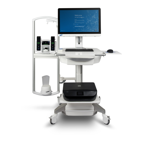
Page 103: Nxt Pro Cart
Hardware 6.8 NXT Pro Cart The NXT Pro Cart (Figure 85), acts as the backbone for the NXT system. Features of the NXT Pro Cart include: • Four-inch swivel castor wheels for curb clearance with brakes for stability. • An adjustable monitor mount (130mm height, +25°/-15° tilt, 180° swivel adjustment, 90°... -
Page 104: T-Doc Air-Charged Catheters
Hardware 6.9 T-DOC Air-Charged Catheters The T-DOC NXT Air-Charged Catheter series are part of the next-generation LABORIE systems designed for use during Urodynamic studies (Figure 87). Figure 87: T-DOC NXT Air-Charged Catheter The T-DOC Air-Charged Catheters are single-use catheters intended for •... -
Page 105: Emg Electrodes
EMG Electrodes The following EMG patches are required for the user to perform a Urology Urodynamic study: Snap-on electrodes (ELE428) and cable (Compatible LABORIE Cables) • For information on how to place the electrodes, refer to the Placing the EMG Patch Electrodes section on page 25. -
Page 106: Appendix
(-10° C to +40° C, 20% to 80% RH Non- Condensing) are labelled on the outside of the packaging. Laborie tests to more extreme conditions to ensure this product can withstand any unexpected conditions which may arise. Laborie has not performed testing to verify system functionality when transported outside of the limits provided NXT Owner’s Manual, NXT-UM01, MAN2010... - Page 107 Appendix Temperature: -20° C to +40° C Storage Conditions Humidity: up to 85 ± 5% RH Non-Condensing IMPORTANT: LABORIE has not performed testing to verify system functionality when stored outside of the limits provided. All-in-one PC Computer: All-in-One medical-grade PC P/N: POC-W243 Screen: 24", 1920 x 1080...
- Page 108 Type BF Applied Part: N/A External Materials: Dow Corning QP1-250, Cycoloy C6200-111, Elastosil 3003/30 A/B, Gold-plated Brass, Loctite 401 & 242 IMPORTANT: LABORIE cannot guarantee the IP47 rating unless the vent plug is inserted into the open vent hole. Remote NXT...
-
Page 109: Classification And Applicable Directives
Appendix Bluetooth Dongle External Power Supply: 5VDC, 35mA max P/N: BTX2001 IP Rating Compliance: IPX0 Type BF Applied Part: N/A Printer Shelf: 10kg Maximum Load Workstation Shelf: 10kg Mouse Tray: 1Kg Accessories External Materials Funnel: Cycolac Resin, Acrylonitrile-butadiene-styrene terpolymer Beaker: Polypropylene Commode: Powder-coated Steel and Plastic EMG Cable (CAB1091, CAB1092): Polyamide and Thermoplastic Elastomer... -
Page 110: Appendix B: Symbols Glossary
Appendix Appendix B: Symbols Glossary Authorized Representative in the European Community Consult Instructions for Date of Manufacture (5.1.2) SGS certification - Use (5.4.3) Read Operator’s Manual Manufacturer (5.1.1) (5.1.3) certified to U.S. and Indicates the (M002) Manufacturer Indicates the device Canadian safety Indicates the date of manufacturer’s device... -
Page 111: Figure 90: Nxt Pro Cart Label Placement
Appendix Protective Earth, Not for general Do Not Stack Grounding waste. This product (2402) (Table D.1, 7) is designated for Indicates the items separate collection Identifies any General Warning Sign shall not be vertically at an appropriate (W001) terminal intended for Safety Label, Safe Safety Label, Safe stacked, either... -
Page 112: Table 16: Guidance And Manufacture's Declaration - Electromagnetic Emissions
EMC information provided in this manual. For EM compliance, it is important to only use catheters and accessories as supplied or recommended by LABORIE. Contact LABORIE for approved catheters. Recommendations for actions to assure that the NXT remains safe regarding EM disturbances: The equipment should be visually inspected regularly for damaged cables and connectors. - Page 113 Appendix Guidance and Manufacturer’s Declaration—Electromagnetic Immunity Immunity IEC 60601 Test Compliance Level Electromagnetic Test Level Environment —Guidance Electrostatic ±8 kV contact ±8 kV contact Floors should be wood, discharge concrete or ceramic tile. If ±15 kV air ±15 kV air (ESD) floors are covered with synthetic material, the...
- Page 114 Appendix Guidance and Manufacturer’s Declaration—Electromagnetic Immunity Immunity test IEC 60601 Test Compliance Level Electromagnetic level Environment—Guidance Portable and mobile RF communications equipment should be used no closer to any part of the NXT, including cables, than the recommended separation distance calculated from the equation applicable to the frequency of the transmitter.
-
Page 115: Table 17: Guidance And Manufacturer's Declaration - Electromagnetic Immunity
Appendix 1970 MHz 28 V/m 2450 MHz 9 V/m 5240/5500/ 5785 MHz Note 1: At 80 MHz and 800 MHz, the higher frequency range applies. Note 2: These guidelines may not apply in all situations. Electromagnetic propagation is affected by absorption and reflection from structures, objects and people. a. -
Page 116: Table 18: Separation Distances Between Portable And Mobile Rf
Appendix Recommended Separation Distances between Portable and Mobile RF Communications Equipment and the NXT The NXT is intended for use in an electromagnetic environment in which radiated RF disturbances are controlled. The customer or the user of the NXT can help prevent electromagnetic interference by maintaining a minimum distance between portable and mobile RF communications equipment (transmitters) and the NXT as recommended below, according to the maximum output power of the communications equipment.
Need help?
Do you have a question about the NXT Series and is the answer not in the manual?
Questions and answers