Table of Contents
Advertisement
Available languages
Available languages
Quick Links
P
n
e
u
m
a
t
i
c
P
n
e
u
m
a
t
i
c
M
a
n
M
a
n
-
P
u
m
p
K
-
1
-
P
u
m
p
K
-
1
u
a
l
/
H
a
n
d
u
a
l
/
H
a
n
d
V7062 02/2017
9
0
0
/
K
-
1
9
5
9
0
0
/
K
-
1
9
5
b
u
c
h
b
u
c
h
KNAUER
Wissenschaftliche Geräte GmbH
Hegauer Weg 38
D - 14163 Berlin, Germany
Tel.: +49 (0)30 809 727 0
Fax: +49 (0)30 801 50 10
E-Mail: info@knauer.net
Internet: www.knauer.net
0
0
Advertisement
Table of Contents

Subscribe to Our Youtube Channel
Related Manuals for Knauer K-1900


Summary of Contents for Knauer K-1900
- Page 1 V7062 02/2017 KNAUER Wissenschaftliche Geräte GmbH Hegauer Weg 38 D - 14163 Berlin, Germany Tel.: +49 (0)30 809 727 0 Fax: +49 (0)30 801 50 10 E-Mail: info@knauer.net Internet: www.knauer.net...
-
Page 2: Table Of Contents
Konventionen in diesem Handbuch ....................19 SOP's in diesem Handbuch ........................ 19 Technische Daten der Pneumatischen Pumpe K–1900 ................20 Inbetriebnahme der Pneumatischen Pumpe K-1900 .................. 20 Auspacken ............................20 Frontansicht der Pneumatischen Pumpe K-1900 ................21 Anschluss der Pneumatischen Pumpe K–1900 .................. 22 Pumpenköpfe und Lösungsmittelanschlüsse .................. -
Page 3: General Description
The characterisics of flow and liquid pressure for the K-1900 with the different pump heads are listed in Table 2, „Technical data of individual pump heads“ on page 6. -
Page 4: Using This Manual
Using this Manual Using this Manual Conventions in this Manual Special Warnings are indicated by the marginal warning sign and printed in bold letters. The marginal lamp symbol indicates helpful advice’s. Important Hints are marked by the marginal hand symbol. SOP’s in this manual The Standard Operating Procedures (SOP) provided with this manual offer a convenient way of structuring complex tasks in the operation of your WellChrom... -
Page 5: Technical Data Of Pneumatic Pump K-1900
Please use the packing list and make sure that the delivery of the Pneumatic Pump K-1900 is complete. If you have any questions regarding complete delivery, please call our service department as soon as possible. Please remove the protection foil from pump outlet. -
Page 6: Front View Of The Pneumatic Pump K-1900
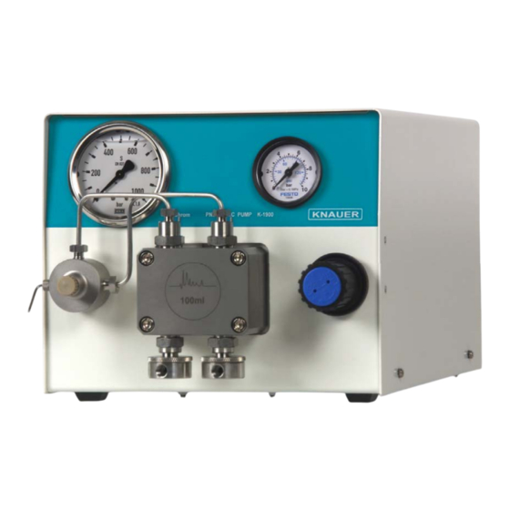
Setup of the Pneumatic Pump K–1900 Front View of the Pneumatic Pump K–1900 All operating elements and hydraulic connections are located on the front of the pump, see Fig. 1 and Fig. 2. Pump head Flushing Valve Eluent pressure gauge Air pressure gauge Regulator for compressed air Fig. -
Page 7: Connecting The Pneumatic Pump K-1900
Pump K–1900 is able to maintain pressures up to 7 bar. With-out back pressure the air consumption would be 80 L/min. If the Pneumatic Pump K-1900 works against pressure the consumption of air is much lower depending on the liquid pressure. -
Page 8: Pump Heads And Hydraulic Connections
Connecting the Pneumatic Pump K–1900 Pump Heads and Hydraulic Connections All operating elements and hydraulic connections are located on the front of the pump, see Fig. 1 and Fig. 2. Make sure that all hydraulic connections are suited for the system pressure and flow rate of your HPLC System. -
Page 9: Setting Up The K-1900
Connecting the Pneumatic Pump K–1900 Setting up the K-1900 Never run the Pneumatic Pump K–1900 without liquid in the pump head or in the piston backflushing compartment. For piston backflushing, follow the instructions below. Operation with-out liquid may lead to damage of the pump seals in short time. -
Page 10: Air Pressure Influences
Connecting the Pneumatic Pump K–1900 SOP 2 Start of Solvent Delivery This SOP applies to the Pneumatic Pump K–1900. Screw a blind fitting to the ”Eluent outlet to column”, Pos. {2.4} in Fig. 2 and open the “De-aeration screw”, Pos. {2.3} for opening flushing valve. Connect the Luer-Lock syringe with the “De-aeration capillary”, Pos. -
Page 11: Calibration For Constant Flow
Connecting the Pneumatic Pump K–1900 Required Compressed Air 250 ml 7 bar 6 bar 5 bar 4 bar 3 bar 2 bar 1 bar Flow Rate [ml/min] Fig. 9 Interdependence of delivery volume and eluent pressure for the 250 ml pump head Required compressed air 1000 ml... -
Page 12: Easy Maintenance
Removing and Checking Piston Rods This SOP refers to the following pump heads: 100 ml stainless steel, KNAUER order number A 4029-1 250 ml stainless steel, KNAUER order number A 4021-1 500 ml stainless steel, KNAUER order number A 4038-1 1000 ml stainless steel, KNAUER order number A 4022-1 Remove Pump head as described in SOP „Removing the Pump Head“. -
Page 13: Knauer
Easy Maintenance SOP 5 Disassembling the Pump Head This SOP refers to the pump heads 100 ml, 250 ml, 500 ml, and 1000 ml. 3.17 3.19 3.10 3.18 3.16 3.15 3.14 3.13 3.11 3.12 3.11 3.10 Pump head housing, front block 3.11 Piston seals Pump head housing, basic plate... -
Page 14: Knauer
SOP 7 Installing the Pump Head This SOP refers to the following pump heads: 100 ml stainless steel, KNAUER order number A 4029-1 250 ml stainless steel, KNAUER order number A 4021-1 500 ml stainless steel, KNAUER order number A 4038-1 1000 ml stainless steel, KNAUER order number A 4022-1 Make sure that the pump head is properly assembled. -
Page 15: Knauer
Cleaning and Replacing Check Valves This SOP refers to the following pump heads: 100 ml stainless steel, KNAUER order number A 4029-1 250 ml stainless steel, KNAUER order number A 4021-1 500 ml stainless steel, KNAUER order number A 4038-1 1000 ml stainless steel, KNAUER order number A 4022-1 If the check valves become dirty they will no longer open and close correctly. -
Page 16: Packing List
Packing List Packing List The delivery of the Pneumatic HPLC Pump K-1900 with the 100 ml, 250 ml, 500 ml, or 1000 ml pump head (order number A50751, A50761, A50771, A50781 comprising the items according to Table 3. Table 3... -
Page 17: Spare Parts And Accessories
Spare Parts and Accessories Spare Parts and Accessories Table 4 KNAUER Order Number User Manual V 7027 Optional Pump Heads Pump Head 100 ml incl. accessory kit A 4029-1 Pump Head 250 ml incl. accessory kit A 4021-1 Pump Head 500 ml incl. accessory kit A 4025-1 Pump Head 1000 ml incl. -
Page 18: Allgemeine Beschreibung Der Pneumatischen Pumpe K-1900
Fluss realisiert werden, als er auf den Pumpenköpfen angegeben ist. Die Zusammenhänge von Fluss und hydraulischem Druck sind für die verschiedenen Pumpenköpfe der K-1900 in Tabelle 2, Technische Daten der einzelnen Pumpenköpfe auf Seite 6 aufgelistet. Die Pumpenköpfe können durch Lösen von nur vier Schrauben ausgetauscht werden. -
Page 19: Hinweise Zum Gebrauch Des Handbuchs
Die Standardarbeitsanweisungen (Standard Operating Procedures, SOP) dieses Handbuches ermöglichen die Strukturierung zusammenhängender Aufgaben beim Betrieb Ihrer Pneumatischen Pumpe K-1900. Sie beinhalten schrittweise Anweisungen, die den Anwender durch alle Aufgaben führen. Sie können gleichfalls zu Dokumentationszwecken genutzt werden. Sie können kopiert, angewendet, unterzeichnet und abgelegt werden, um so die Leistungsfähigkeit Ihres Gerätes zu dokumentieren. -
Page 20: Technische Daten Der Pneumatischen Pumpe K-1900
Schäden fallen nicht unter die Garantiegewährleistung. Inbetriebnahme der Pneumatischen Pumpe K-1900 Auspacken Alle KNAUER-Geräte werden ab Werk sorgfältig und sicher für den Transport verpackt. Prüfen Sie dennoch nach dem Auspacken alle Geräteteile und das Zubehör auf mögliche Transportschäden und machen Sie gegebenenfalls Schadensersatzansprüche sofort beim Transportunternehmen geltend. -
Page 21: Frontansicht Der Pneumatischen Pumpe K-1900
Inbetriebnahme der Pneumatischen Pumpe K-1900 Frontansicht der Pneumatischen Pumpe K-1900 Alle Bedienelemente und hydraulischen Anschlüsse befinden sich an der Frontseite der Pumpe, siehe Abb. 1 Pumpenkopf Druckaufnehmer Manometer, Flüssigkeit Manometer, Pressluft Druckluftregler Abb. 1 Frontansicht mit Pumpenkopf und Druckaufnehmer Pumpenkopf Druckaufnehmer 1.1 Kolbenhinterspülungskapillare... -
Page 22: Anschluss Der Pneumatischen Pumpe K-1900
Die aufgedruckten Flussraten von 100 ml/min, 250 ml/min, 500 ml/min beziehungsweise 1000 ml/min sind die Maximalwerte dieser Pumpenköpfe bei ihrem Einsatz mit der HPLC-Pumpe K-1800. Die mit der Pneumatischen Pumpe K-1900 erreichbaren maximalen Flüsse sind (als Faustregel) um den Faktor zwei größer. Abb. 4... -
Page 23: Flüssigkeitsverbindungen
Vorderseite Pneumatische Pumpe K-1900, siehe Abb. 1 auf Seite 22. Bitte achten Sie sowohl beim ersten Setup der Pumpe, als auch bei jedem späteren Lösungsmittelwechsel strikt auf die Mischbarkeit der nach- einander verwendeten Lösungsmittel, da sonst die Funktion der Kugel- ventile nachteilig beeinflusst werden kann, siehe Abb. -
Page 24: Betriebsvorbereitung
(meistens Wasser) gemäß der folgenden SOP zu hinterspülen. SOP 1 Einrichtung der Pneumatische Pumpe K-1900 für die Kolbenhinterspülung Diese SOP gilt für die Pneumatische Pumpe K-1900. Schieben Sie zwei Schlauchstücke mit einem Innendurchmesser von 1/16“ über die Anschlüsse für die Kolbenhinterspülung. Abb. 7 Kapillaranschlüsse für die Kolbenhinterspülung... -
Page 25: Pressluftdruck Und Flüssigkeitsdruck Und -Fluss
Inbetriebnahme der Pneumatischen Pumpe K-1900 SOP 2 Starten der Lösungsmittelförderung Schrauben Sie den auf den Flüssigkeitsauslass zum Verschlussstopfen System , Pos. {2.4} in Abb. 2 und öffnen Sie die Belüftungsschraube, Pos. {2.3}. Verbinden Sie die Luer-Lock Spritze mittels eines kurzen PTFE- Schlauchstückes (ID 1,5 mm/ OD 2,1 mm) mit der Entlüftungskapillare”,... -
Page 26: Kalibrierung Für Konstanten Fluss
Zur Kalibrierung müssen Sie den Fluss bei verschiedenen Pressluftdrücken von 1 bis 7 bar (bis 4,2 bar für den 100 ml-Pumpenkopf) messen. Säule 1 Säule 2 Abb. 11 Typische Kalibrierkurven der pneumatischen Pumpe K-1900 für zwei unterschiedliche Säulen (250 ml-Kopf) -
Page 27: Wartung Durch Den Anwender
Wartung durch den Anwender Austausch und Reinigung des Pumpenkopfes SOP 3 Pumpenkopf ausbauen Diese SOP gilt für die Pneumatische Pumpe K-1900. Zum Wechsel des Pumpenkopfes, zum Demontieren zwecks Reinigung oder Austauschs von Kolbenstangen oder -dichtungen kann dieser einfach vom Pumpengehäuse abgenommen werden: Spülen Sie den Pumpenkopf mit geeigneter Spülflüssigkeit und danach... -
Page 28: Knauer
Wartung durch den Anwender SOP 5 Pumpenkopf zerlegen Diese SOP gilt für die 100 ml, 250 ml, 500 ml und 1000 ml Pumpenköpfe. 3.17 3.19 3.10 3.18 3.16 3.15 3.14 3.13 3.11 3.12 3.11 3.10 Pumpenkopf, Frontblock 3.11 Kolbendichtungen Pumpenkopf, Basisplatte 3.12 O-Ringe Kolbenhinterspülungs-... -
Page 29: Knauer
10. Die Schrauben der Grundplatte, Pos. {3.19} müssen dann wieder sehr fest angezogen werden. SOP 7 Pumpenkopf einbauen Diese SOP gilt für die WellChrom Pumpe K-1900 und folgende Pumpenköpfe: 100 ml Edelstahl, KNAUER Bestellnummer A 4029-1 250 ml Edelstahl, KNAUER Bestellnummer A 4021-1 500 ml Edelstahl, KNAUER Bestellnummer A 4038-1 1000 ml Edelstahl, KNAUER Bestellnummer A 4022-1 Stellen Sie sicher, dass der Pumpenkopf richtig zusammengesetzt ist. -
Page 30: Knauer
Kugelventile reinigen und ersetzen Diese SOP gilt für die folgende Pumpenköpfe: 100 ml Edelstahl, KNAUER Bestellnummer A 4029-1 250 ml Edelstahl, KNAUER Bestellnummer A 4021- 1 500 ml Edelstahl, KNAUER Bestellnummer A 4038-1 1000 ml Edelstahl, KNAUER Bestellnummer A 4022-1 Wenn die Kugelventile verschmutzen, öffnen und schließen sie nicht mehr... -
Page 31: Lieferumfang
Lieferumfang Lieferumfang Die Lieferung der Pneumatischen Pumpe K-1900 mit einem 100 ml-, 250 ml-, 500ml- oder 1000 ml-Pumpenkopf (Bestellnummer A50751, A50761, A50771, A50781 ) beinhaltet die Positionen gemäß Tabelle 3. Tabelle 3 Lieferumfang der Pneumatischen Pumpe K-1900 Teile Beschreibung Grundeinheit der Pumpe Benutzerhandbuch Schlauchanschluss für die Druckluft... -
Page 32: Ersatzteile Und Zubehör
Ersatzteile und Zubehör Ersatzteile und Zubehör Tabelle 4 KNAUER Bestellnummer Benutzerhandbuch V 7027 Optionale Pumpenköpfe 100 ml-Pumpenkopf mit Zubehör A 4029-1 250 ml-Pumpenkopf mit Zubehör A 4021-1 500 ml-Pumpenkopf mit Zubehör A 4021-1 1000 ml-Pumpenkopf mit Zubehör A 4022-1 Kühlvorrichtung für alle Pumpenköpfe... -
Page 33: Warranty Statement
Warranty statement Warranty statement The warranty period of the WellChrom Pneumatic Pump K-1900 is 12 months beginning from the date of dispatch from Berlin. Operation inconsistent with manufacturer's instructions or damage caused by unauthorized service personnel are excluded from guarantee. Damage caused by blockages and wear and tear parts such as fuses and seals are not covered by the guarantee. -
Page 34: Declaration Of Conformity
Declaration of conformity Declaration of conformity The Declaration of Conformity is part of the delivery and accompanies the product as a separate document. Konformitätserklärung Die Konformitätserklärung ist Bestandteil des Produktes und liegt als separates Dokument dem Produkt bei.
Need help?
Do you have a question about the K-1900 and is the answer not in the manual?
Questions and answers