Advertisement
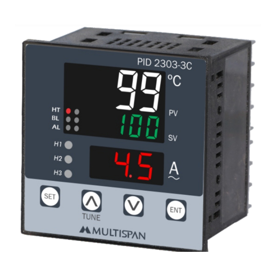
PV = Process value
SV = Set value
TECHNICAL SPECIFICATION
INPUT SPECIFICATION:
Input
J
Input Types
K
3 CT
Resolution
J,K = 1°C
Indication
±1% of FSD ± 1°C
Accuracy
(FSD:- full scale deflection)
DISPLAY AND KEYS:
Upper: 4 digit, 7 seg 0.56" white LED
Display
Middle: 4 digit, 7 seg, 0.31" green LED
Lower: 3 digit, 7 seg, 0.39" red LED
Keys
SET, INC, DEC, ENT
DIMENSION:
Size (mm)
72 (H) x 72 (W) x 85 (D) mm
68 (H) x 68 (W) mm
Panel Cutout
CONTROL METHOD:
1) PID control with Auto-Tuning
Heating
2) ON-OFF control
1) BL.TP ( Blower Time Proportion)
Cooling
2) ON-OFF control
Heater break alarm, Cold start, High,
Alarm
Absolute low, Inband, Absolute outband
PID CONTROLLER
PID 2303-3C
Range
0 to 400°C
0 to 500°C
0.0 to 30.0 A
OUTPUT SPECIFICATION:
Relay Output
Relays
3 Nos
Relay Type
st
1 Relay 1C/O & 2 & 3 Relay (NO-C)
Rating
10A,230V AC/28V DC
SSR Drive Output
24V DC, 30mA DC
(On-Off condition)
Output Signal
Relay 1 parallel to SSR
POWER SUPPLY:
Supply Voltage
Power Consuption
(VA Rating)
ENVIRONMENT CONDITION:
Operating Temp.
Relative Humidity
Protection Level
MECHANICAL INSTALLATION
Outline Dimension (mm)
PID 2303-3C
99
ºC
PV
100
HT
BL
SV
AL
72
H1
45
H2
H3
SET
TUNE
72
3
TERMINAL CONNECTION
1
L
~
100
250V AC
2
N
50/60 Hz
6VA
3
NO
4
C
RELAY-1
5
NC
-
6
www.multispanindia.com
S.S.R
7
H1
18
Made in India
nd
rd
100 to 250V AC, 50-60Hz
Approx 6VA @ 230V AC
0°C to 55°C
UP to 95% RH
(non-condensing)
IP-65 (Front side) As per IS/IEC
60529 : 2001
Panel Cutout
Dimension (mm)
68
85
15
16
17
CT
8
COM.
TC
9
-
10
!
11
C
RELAY-3
12
NO
13
C
RELAY-2
14
NO
H2
H3
19
20
68
Page 1
Advertisement
Table of Contents

Subscribe to Our Youtube Channel
Related Manuals for MULTISPAN PID 2303-3C


Summary of Contents for MULTISPAN PID 2303-3C
- Page 1 PID CONTROLLER OUTPUT SPECIFICATION: PID 2303-3C Relay Output Relays 3 Nos Relay Type 1 Relay 1C/O & 2 & 3 Relay (NO-C) Rating 10A,230V AC/28V DC SSR Drive Output 24V DC, 30mA DC (On-Off condition) Output Signal Relay 1 parallel to SSR...
-
Page 2: Maintenance
STATUS LED DESCRIPTION WARNING GUIDELINES 8899 WARNING : Risk of electric shock. 1. To prevent the risk of electric shock power, supply to the equipment must be kept OFF while doing the wiring 8100 arrangement. Do not touch the terminals while power is being supplied. -
Page 3: Error Display
ERROR DISPLAY PARAMETER MESSAGE DESCRIPTION When an error has occurred the display indicates error codes Parameter Description as given below. Input INPT ERROR MEANING Sensor is not connected or OPEN Over range condition or Relay 1 Mode R1MD sensor break HEAT Heating PID Action... -
Page 4: Parameter Range
WORKING PARAMETER RANGE R1-Heating Parameter Range For J, K 1) Control Mode PID: Relay turning ON/OFF according to heat 0.0°C to 999.9°C requirement of the machine. 0 to 9999 2) Control Mode ON/OFF: Relay turns ON (and remains ON) when PV <... -
Page 5: Parameter Setting
PARAMETER SETTING Set Point Setting Case 1 :- If HBA Select Process Value r3md Relay 3 Mode Set Value ALRM Alarm Ampere set1 HbAL Heater Break Alarm Set Point-1 Set Point 1 Press key for 4 sec to enter Password HBAL Heater Break Alarm pass... - Page 6 PARAMETER SETTING Control Parameter Case 3 :- INB, ABO pass SET3 Enter Password 37 Set Point 3 SET3 Set Point 3 PID Action HI H High Proportional Band ALRM Alarm time TIME time Integral Time HB-1 Heater 1 Break Indication Set Point Derivative Time HB-1...
-
Page 7: Alarm Operation
ALARM OPERATION ABSOLUTE OUTBAND ALARM R3-Alarms RLY-ON 1) Heater Break alarm: - If the current of the Heater < AMP SV (unhealthy condition) then Relay turns ON and Upper RLY-OFF Display will show , middle display will blink showing . To manually turn off Relay, press ENT key 4 sec.
Need help?
Do you have a question about the PID 2303-3C and is the answer not in the manual?
Questions and answers