Advertisement
Quick Links
TECHNICAL SPECIFICATION
INPUT SPECIFICATION:
Primary CT value
Secondary current AC
Resolution
DISPLAY AND KEYS:
Upper: 4 digit, 7 segment, 0.70" White
Display
Lower: 4 digit, 7 segment, 0.50" Green
Keys
SET, INC, DEC, ENTER/RESET
DIMENSION:
Size
96 (H) x 96 (W) x 43 (D) mm
Panel Cutout
92 (H) x 92 (W) mm
OUTPUT SPECIFICATION:
Relay Output
Relay
1 Nos
Relay Type
1C/O (NO-C-NC)
Rating
10A, 230V AC / 28V DC
POWER SUPPLY:
Supply
Voltage
Power
Consuption
(VA Rating)
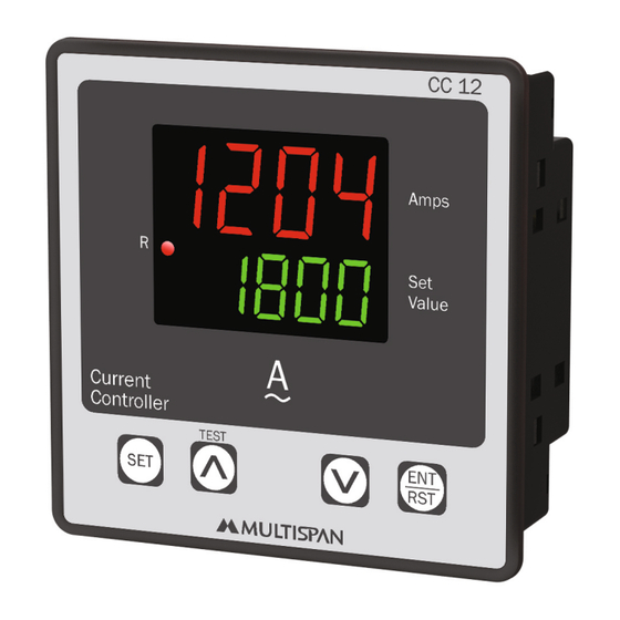
CURRENT CONTROLLER
5 to 4000 Selectable
0.5 to 5 Amp AC
0.1A, 1A
100 to 270V AC, 50-60Hz
4VA @ 230V AC MAX
TIME PARAMETER :
CC-12
Time 1
Time 2
ENVIRONMENT CONDITION:
Operating Temp.
Relative Humidity
Protection Level
(As per request)
Outline Dimension (mm)
1
2 0
R
8 1 00
96
Current
Controller
TEST
SET
96
20
19
C
NC
RELAY-1
Made in India
100
~
270AC
50/60 Hz
L
N
1
2
It is a minimum relay off delay, where
relay 1 is on for minimum time when
Amp. reach to the set 1
It is a trip delay, if Amp. value is greater
than set 2 for the amount of trip time
than relay 2 is on after trip time
0°C to 55°C
UP to 95% RH
(non-condensing)
IP-65 (Front side) As per IS/IEC
60529 : 2001
MECHANICAL INSTALLATION
CC 12
4
Amps
Set
Value
ENT
RST
3
43
TERMINAL CONNECTION
18
17
16
15
NO
Input :
0 to 5 Amp AC
Range:
5 to 4000 CT SELE
Output:
1R1C/O
5
3
4
6
Panel Cutout
Dimension (mm)
92
92
14 13
12
11
www.multispanindia.com
0 To 5A AC
I/P
9
7
8
10
Advertisement

Subscribe to Our Youtube Channel
Related Manuals for MULTISPAN CC-12


Summary of Contents for MULTISPAN CC-12
- Page 1 CURRENT CONTROLLER TIME PARAMETER : CC-12 It is a minimum relay off delay, where relay 1 is on for minimum time when Time 1 Amp. reach to the set 1 It is a trip delay, if Amp. value is greater...
- Page 2 STATUS LED DESCRIPTION WARNING GUIDELINES WARNING : Risk of electric shock. 2345 1. To prevent the risk of electric shock, power supply to the equipment must be kept OFF while doing the wiring arrangement. Do not touch the terminals while power is being supplied.
- Page 3 PARAMETER SETTING CONTROL FUNCTION LOW ALARM: Press Press & 0.0 to CT Primary Value HYST 1000 to set setpoint value Press Hysteresis RLY-OFF Press & 0.1 TO 99.9 0000 Delay RLY-ON Delay Press Time Time Stdt Starting Delay time Press &...
- Page 4 CONTROL FUNCTION OUTBAND ALARM RLY-ON RLY-OFF HYST RLY-OFF RLY-ON Delay Delay Delay Time Time Time ABSOLUTE LOW ALARM RLY-OFF HYST RLY-ON RLY-OFF RLY-ON Delay RLY-OFF Time ABSOLUTE OUTBAND ALARM RLY-ON RLY-OFF HYST RLY-OFF RLY-ON Delay Delay Time Time RLY-OFF RLY-ON...
Need help?
Do you have a question about the CC-12 and is the answer not in the manual?
Questions and answers
Multispan cc12 need a pass
The passcode for the Multispan CC-12 is not provided in the given context.
This answer is automatically generated