Table of Contents
Advertisement
Quick Links
Advertisement
Table of Contents

Related Manuals for KSB CHTRa


Summary of Contents for KSB CHTRa
- Page 1 Process Pump CHTRa Installation/Operating Manual...
- Page 2 All rights reserved. The contents provided herein must neither be distributed, copied, reproduced, edited or processed for any other purpose, nor otherwise transmitted, published or made available to a third party without the manufacturer's express written consent. Subject to technical modification without prior notice. © KSB SE & Co. KGaA, Frankenthal 06/09/2018...
-
Page 3: Table Of Contents
Dismantling the coupling guard ....................... 28 5.6.2 Dismantling the coupling cover (if applicable) ................ 29 5.6.3 Dismantling the coupling spacer ...................... 29 Mounting the coupling hubs ......................... 29 5.7.1 Checking the shaft ends for run-out .................... 30 5.7.2 Fitting the coupling hubs (with key) .................... 30 CHTRa 3 of 116... - Page 4 6.2.12 Setting the lube oil supply (if applicable) .................. 56 6.2.13 Priming the pump and piping...................... 57 Commissioning/Start-up .......................... 58 6.3.1 Prerequisites for commissioning/start-up .................. 58 6.3.2 Checks prior to commissioning/start-up ................... 58 6.3.3 Start-up and trial run......................... 59 Checklist for commissioning/start-up ...................... 62 Operation................................ 62 CHTRa 4 of 116...
- Page 5 Ordering spare parts.......................... 98 7.5.2 Storing spare parts.......................... 98 7.5.3 Recommended spare parts stock for two years' operation............. 98 Trouble-shooting.......................... 99 EU Declaration of Conformity ...................... 102 Related Documents .......................... 103 10.2.5 Permissible vibrations on bearing housings ................... 108 Index .............................. 113 CHTRa 5 of 116...
-
Page 6: Glossary
Discharge line The pipeline which is connected to the discharge nozzle Pump Machine without drive, additional components or accessories Pump set Complete pump set consisting of pump, drive, additional components and accessories CHTRa 6 of 116... -
Page 7: General
KSB’s specialist team. In the event of damage, immediately contact your nearest KSB Service centre to maintain the right to claim under warranty. 1.2 Installation of partly completed machinery To install partly completed machinery supplied by KSB refer to the sub-sections under Servicing/Maintenance. -
Page 8: Symbols
✓ Conditions which need to be fulfilled before proceeding with the step-by-step instructions ⊳ Safety instructions ⇨ Result of an action Cross-references ⇨ Step-by-step instructions Note Recommendations and important information on how to handle the product CHTRa 8 of 116... -
Page 9: Safety
This applies to, for example: ▪ Arrow indicating the direction of rotation ▪ Markings for connections ▪ Name plate The operator is responsible for ensuring compliance with all local regulations not taken into account in this operating manual. CHTRa 9 of 116... -
Page 10: Intended Use
▪ Only use the pump to handle the fluids described in the data sheet or product literature of the pump model or variant. ▪ The pump must only be operated with the components selected by KSB. ▪ Never operate the pump without the fluid to be handled. -
Page 11: Safety Awareness
Before returning the product to service, observe all instructions on commissioning. 2.9 Unauthorised modes of operation Never operate the pump (set) outside the limits stated in the data sheet and in this manual. CHTRa 11 of 116... -
Page 12: Explosion Protection
(a potential temperature rise in the shaft seal area has been taken into account). Table 3: Temperature limits [°C] Temperature class to EN 13463-1 or Maximum permissible temperature of the ISO 80079-36 fluid handled [°C] Temperature limit of the pump Temperature limit of the pump CHTRa 12 of 116... -
Page 13: Monitoring Equipment
Check whether monitoring equipment is required to ensure that the pump set functions properly. Contact KSB for further information about monitoring equipment. 2.10.4 Operating limits The minimum flows indicated in (ð Section 6.6.3.1, Page 66) refer to water and water-like fluids handled. -
Page 14: Transport/Temporary Storage/Disposal
3.1 Checking the condition upon delivery Check each packaging unit for damage before it is stored In the event of in-transit damage, assess the exact damage, document it and notify KSB about the damage in writing immediately. 3.2 Transporting the packaged components of the pump set ü... -
Page 15: Transport
To determine the lifting capacity, pay attention to the position of the centre of gravity, the angle of spread and permissible bending radii of the lifting accessories attached to the load to be lifted. To transport the pump/pump set suspend it from the lifting tackle as shown. CHTRa 15 of 116... - Page 16 The angle α depends on the lifting tackle; however it must never be wider than 120°. Transporting the pump set Fig. 2: Centreline pump feet Fig. 3: Transport using a transportation beam Transporting the pump on the baseplate Fig. 4: Separate baseplate for pump Fig. 5: Common baseplate for pump and drive CHTRa 16 of 116...
-
Page 17: Transporting The Pump Rotor
Danger to life from falling parts! ▷ Never use steel ropes or chains for transport. ▷ Use manila ropes or plastic ropes. ▷ Transport the rotor in a horizontal position. Transport the pump rotor as shown. CHTRa 17 of 116... -
Page 18: Transporting The Accessories
▷ Transport accessories by hand, if possible. If this is not an option because of the weight, observe the transport options described in this manual. Attach the lifting accessories as illustrated or as instructed in the product literature of the respective manufacturer. CHTRa 18 of 116... -
Page 19: Storage/Preservation
CAUTION Damage during storage due to humidity, dirt or vermin Corrosion/contamination of the pump (set)! ▷ For outdoor storage cover the pump (set) or the packaged pump (set) and accessories with waterproof material. CHTRa 19 of 116... - Page 20 Period of storage longer If the requisite preservation measures have not been performed by KSB (special than 12 months preservation), they must be discussed with and approved by KSB prior to putting the pump into storage. Table 6: Measures to be taken for preservation...
-
Page 21: Return To Supplier
Collect greases and other lubricants during dismantling. 2. Separate and sort the pump materials, e.g. by: - Metals - Plastics - Electronic waste - Greases and other lubricants 3. Dispose of materials in accordance with local regulations or in another controlled manner. CHTRa 21 of 116... -
Page 22: Description Of The Pump (Set)
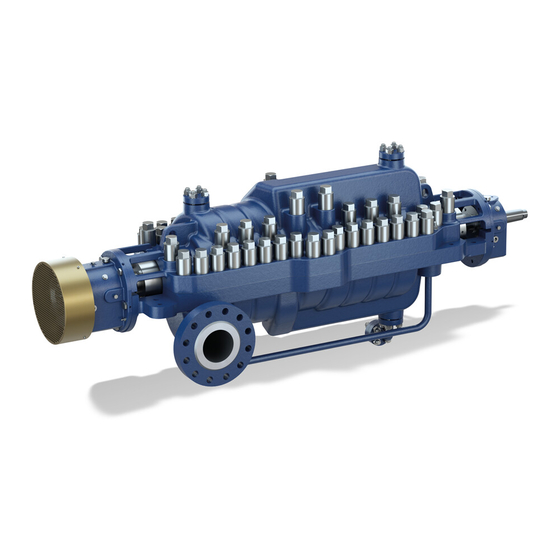
Pump for handling hydrocarbons, boiler feed water, clean cold or hot water or aqueous solutions employed in refineries, refinery off-sites and in the petrochemical industry. ▪ Process pump to API 610 ▪ Multistage volute casing pump 4.2 Designation Example: CHTRa-S 3x6x9-5 8 Table 7: Designation key Code Description Type series Additional code... -
Page 23: Design Details
▪ Optional: Plain bearing/Pivoted segmental thrust bearing ▪ Labyrinth rings ▪ Integrated oil thrower ▪ Non-drive-end fan cooling ▪ Optional: drive-end fan cooling ▪ Oil mist lubrication ▪ Optional: external oil supply Available for most sizes CHTRa 23 of 116... -
Page 24: Configuration And Function
Balance bush Balance drum Upper half of pump casing Mechanical seal Shaft Lower half of pump casing Bearings 4.6 Order specifications Project: KSB order number: Type series, size: Item number: Table 8: Technical data Characteristic Value Unit Fluid handled Operating °C... - Page 25 Sectional drawing Piping & instrumentation diagram Table 12: Documents of devices for fitting and removal of components Description Drawing number Comment Puller & pusher kit Removal of balance bush 605, rolling element bearings and balance drum As-built dimensions CHTRa 25 of 116...
-
Page 26: Installation At Site
DANGER Insufficient stability of pump set as a result of incorrect dimensioning and fastening of the baseplate (unless included in KSB's scope of supply) Risk of pump tipping over! ▷ Prior to commissioning, provide proof that the baseplate is adequately dimensioned to ensure the pump set’s stability, and proof of compliance with... -
Page 27: Unpacking The Pump Set Components
▪ Spare parts and parts which are not immediately needed must be stored. NOTE If components of the pump set became damaged, wet or dirty, inform KSB. 5.4 Removing the preservation NOTE If the pump has been specially preserved for storage of more than 12 months or sea transport, the necessary measures for removal of preservation prior to installation must be carried out. -
Page 28: Transporting The Pump Set Components To The Place Of Installation
Coupling guard (example) Coupling cover (example) Bottom plate Foot fastening (lock strip) 1. Undo and remove the bottom plate. 2. Undo the foot fastening. 3. Remove the coupling guard upwards. 4. Store coupling guard, if required. CHTRa 28 of 116... -
Page 29: Dismantling The Coupling Cover (If Applicable)
Damage to bearings and coupling parts! ▷ Remove coupling hubs using a puller. ▷ Never strike the coupling hubs. WARNING Falling coupling parts Risk of crushing from falling parts! ▷ Secure coupling parts against falling down. ▷ Wear safety shoes. CHTRa 29 of 116... -
Page 30: Checking The Shaft Ends For Run-Out
Observe the marking between coupling hub and shaft. (ð Section 7.3.4, Page 82) 1. Permissible tolerance at the pump shaft ≤ 0.03 mm/ 0.0012 inch. If this value is exceeded, inform KSB. 2. After every 90° turn, read measured values again. 3. Permissible tolerance at the motor shaft, see the data provided by the manufacturer. -
Page 31: Preparing The Adjusting Screws
6. Securely tighten the grub screws. 7. Fit the retaining ring, if applicable, to the coupling hub. 5.8 Preparing the adjusting screws Prepare the adjusting screws and position them on either side of the foundation bolts as shown in the sketch. CHTRa 31 of 116... -
Page 32: Installing The Pump Set
5. Check the baseplate alignment once again in relation to the foot supporting surfaces both parallel to and 90° to the foundation centreline using a spirit level (accuracy < 0.3 mm/m). Correct any deviations which might have occurred under the load of the components using the levelling screws. CHTRa 32 of 116... -
Page 33: Securing The Baseplate With Bonded Anchors
The plates for the special foundation bolts must rest evenly on the foundation. 7. Tighten the nut of the special foundation bolts. Refer to the general arrangement drawing for bolt tightening torque. CHTRa 33 of 116... -
Page 34: General Information On Alignment
This rotor position must not be altered during the full duration of alignment work. ▪ Check the distance between the coupling hubs for compliance with the installation plan, and adjust if required. CHTRa 34 of 116... -
Page 35: Checking The Coupling Alignment
Fig. 16: Run-out check with outside step (example) Check each coupling hub for run-out using a dial gauge. The run-out must not exceed 0.03 mm; if it is exceeded, contact KSB. 5.11.2 Checking the coupling alignment with a dial gauge Perform the alignment with dial gauges in accordance with the manufacturer’s product literature. -
Page 36: Checking The Coupling Alignment With A Laser Device
Always observe the radial displacement and angular misalignment as well as the axial distance indicated by the coupling manufacturer. 5.11.4.1 Radial displacement Fig. 19: Radial displacement (example) The radial displacement V must not deviate more than 0.03 mm from the nominal value, measured at a distance of 90°. CHTRa 36 of 116... -
Page 37: Determining Misalignment And Correct Vertical Plane
Because of the thermal expansion of the pump and the associated displacement of the pump feet, the position of the holes must be marked accordingly. CHTRa 37 of 116... -
Page 38: Fastening The Baseplate To The Foundation
(e.g. Pagel concrete grout), minimum compressive strength class C 25/30, grain size ≤ 8 mm. The remaining 2/3 of the fields may be filled with standard concrete of this quality. KSB recommends that all fields be completely grouted with non-shrinking concrete grout. Produce flowability with the help of a solvent. -
Page 39: Securing The Baseplate With Special Foundation Bolts
(e.g. Pagel concrete grout), minimum compressive strength class C 25/30, grain size ≤ 8 mm. The remaining 2/3 of the fields may be filled with standard concrete of this quality. KSB recommends that all fields be completely grouted with non-shrinking concrete grout. Produce flowability with the help of a solvent. -
Page 40: Cleaning The Piplines
(offset at flange connections and pipe unions is not permitted.). ▪ Pipes supplied by KSB have been cleaned and closed. Nevertheless their interior must be checked for impurities which might have been caused afterwards and be cleaned, if required. -
Page 41: Fitting A Strainer/Filter (Optional)
2. Install the strainer in the inlet line as close to the pump nozzle as possible. 3. For differential pressure monitoring a drilled hole is provided upstream and downstream of the strainer insert or at the strainer housing. CHTRa 41 of 116... -
Page 42: Minimum Flow System
Incorrect earthing during welding work at the piping Destruction of rolling element bearings (pitting effect)! ▷ Never earth the electric welding equipment on the pump or baseplate. ▷ Prevent current flowing through the rolling element bearings. CHTRa 42 of 116... - Page 43 Where fluid has to be pumped out of a vessel under vacuum, installing a vacuum balance line is recommended. The following rules apply to vacuum balance lines: ▪ Minimum nominal line diameter 25 mm. ▪ The line extends above the highest permissible fluid level in the vessel. CHTRa 43 of 116...
-
Page 44: Bypass And Balancing Lines
Damage to the mains network, short circuit! ▷ Observe the technical specifications of the local energy supply companies. 1. Check the available mains voltage against the data on the motor name plate. 2. Select an appropriate starting method. CHTRa 44 of 116... -
Page 45: Earthing
2. Tighten the nuts on the discharge side/non-drive end so that the discs may still be moved by means of slight hammer blows. 3. Lock all nuts using an additional nut. 5.18.2 Pinning the pump feet Fig. 25: Pinning the pump feet CHTRa 45 of 116... -
Page 46: Installing Or Connecting The Measuring Instruments
2. Fasten the instrument leads at the intended connection points and install them according to the constraints on site. 3. Run the electric connecting cables in cable conduits until just before reaching the measuring point and have them connected by authorised personnel. CHTRa 46 of 116... -
Page 47: Preservation For Standstill
Check all pipe connections for parallelism. Fine-align all components making up the set(s) using dial gauge with 0.1 mm scale divisions. Record the readings in the KSB alignment/ taking-over certificate. Pin the pump (set) on the baseplate. Check variable spring hangers, if fitted, for proper functioning. -
Page 48: Commissioning/Start-Up/Shutdown
▷ Observe all legal regulations on the disposal of fluids posing a health hazard. 6.2.1.1 Internal preservation If the pump has been filled with a glycol/water mixture for preservation, this mixture has to be drained prior to any further work. CHTRa 48 of 116... -
Page 49: Work To Be Carried Out Prior To Restart After Standstill > 12 Months
50 K. Oil quality When operating the pumps in potentially explosive atmospheres, lubricants have to be selected whose ignition temperature/flash point exceeds the maximum surface temperature of the pump by at least 50 K. Recommended oil types (ð Section 10.5, Page 112) CHTRa 49 of 116... -
Page 50: Filling In Lubricants (If Applicable)
▷ The ignition temperature of the lubricant should exceed the maximum surface temperature of the pump by at least 50 K. CAUTION Incorrect oil level in bearing housing Damage to the pump! ▷ Check the oil level only during standstill of the pump! CHTRa 50 of 116... - Page 51 5. After a short time check whether the oil level in the reservoir has dropped. It is important to keep at least one third of the reservoir filled at all times. If the oil level is too low, top it up with oil. CHTRa 51 of 116...
-
Page 52: Checking The Direction Of Rotation
Starting of the motor for checking the direction of rotation Risk of injury due to contact with unprotected or rotating parts or parts flying off! ▷ Remove or fasten any movable parts on the motor shaft. ▷ Never touch any unprotected, rotating parts. CHTRa 52 of 116... -
Page 53: Checking The Rotatability Of The Pump Rotor
1. Mount and align the spacer (if any) of the coupling as described in the manufacturer’s product literature. 2. Connect the coupling hubs with the spacer and the disc packs. For this purpose, insert the screws/bolts and tighten the nuts. Observe the tightening torques. CHTRa 53 of 116... -
Page 54: Fitting The Protective Equipment
Risk of injury by rotating shafts! ▷ Always operate the pump set with a coupling guard. If the customer specifically requests not to include a coupling guard in KSB's delivery, then the operator must supply one! ▷ Observe all relevant regulations for selecting a coupling guard. - Page 55 8. Fix the upper and lower halves with 2 taper pins and fasten with screws. 9. Connect the pipes to the cover. 6.2.9.3 Fitting the contact guard for the shaft seal Fasten the contact guard to the pump casing by means of screws. CHTRa 55 of 116...
-
Page 56: Functional Test And Adjustment Of The Instruments
3. Check the oil level and top up, if required. 4. Switch on the oil supply unit or auxiliary oil pump and check the oil pressure. CHTRa 56 of 116... -
Page 57: Priming The Pump And Piping
11. Vent all pressure gauge lines until there is no more air to escape. 12. Fully open the shut-off element in the inlet pipe. 13. Check whether inlet pressure is available. CHTRa 57 of 116... -
Page 58: Commissioning/Start-Up
▪ The connection for tapping, if applicable, is closed. ▪ The shut-off elements in the bypass line are open. ▪ The cooling water system is ON. ▪ The cooling liquid pressure at the inlet must not exceed 6 bar. CHTRa 58 of 116... -
Page 59: Start-Up And Trial Run
Risk of burns! ▷ Do not touch hot surfaces. CAUTION Abnormal noises, vibrations, temperatures or leakage Damage to the pump! ▷ Switch off the pump (set) immediately. ▷ Eliminate the causes before returning the pump set to service. CHTRa 59 of 116... - Page 60 2. Switch on the turning gear, if any, and observe the turbine manufacturer’s instructions on starting of the pump set. 3. If pre-warming is provided, open the valve in the pre-warming line. 4. Switch on the cooling water (if applicable). CHTRa 60 of 116...
- Page 61 10. Slowly open the shut-off valve of the discharge line until it is completely open. When starting against an open shut-off valve in the discharge line, consider the higher power input required. 11. Continuously monitor the pump set’s operating behaviour. CHTRa 61 of 116...
-
Page 62: Checklist For Commissioning/Start-Up
Hot or toxic fluids escaping! ▷ Never operate the pump with the shut-off elements in the suction line and/or discharge line closed. ▷ Only start up the pump set with the discharge-side shut-off element slightly or fully open. CHTRa 62 of 116... - Page 63 Failure of seal elements on suction and discharge nozzles and other pressurised parts Risk of personal injury in the event that hot, pressurised fluid handled escapes! ▷ Wear safety goggles. ▷ Check seal elements regularly. ▷ Access to the pump is permitted to authorised specialist personnel only. CHTRa 63 of 116...
-
Page 64: Operating Limits
▷ In case of explosion-proof motors, observe the frequency of starts specified in the manufacturer's product literature. CAUTION Excessively high switching frequency Damage to the balancing device! ▷ Do not exceed the values for the frequency of starts. CHTRa 64 of 116... -
Page 65: Ambient Temperature
Maximum 50 °C Minimum - 20 °C For operation at temperatures outside the permissible limits, contact KSB. Bearing oil temperature The minimum permissible bearing oil temperature when starting the pump depends upon the quality of oil used: DANGER Temperature increase due to insufficient lubrication... -
Page 66: Fluid Handled
When the pump handles fluids containing abrasive substances, increased wear of the hydraulic system and shaft seal are to be expected. In this case, reduce the commonly recommended inspection intervals. Maximum permissible flow rate Minimum permissible flow rate Best efficiency point CHTRa 66 of 116... -
Page 67: Measures To Be Taken For Shutdown
6.7.1.3 Turbine-driven pump set with non-synchronised turning gear ▪ Following standstill of the pump set (n = 0 rpm) the turning gear must take over the turning of the rotor within a period of 10 seconds.. CHTRa 67 of 116... -
Page 68: Shutdown For Maintenance Of The Pump Set Or Prolonged Standstill
6. Close the shut-off valve in the minimum flow line. 7. Close the shut-off element in the inlet line. 8. Turn off the cooling water supply when the casing temperature (measured at the pump nozzles) is lower than 50 °C. 9. Close all other pipes. CHTRa 68 of 116... -
Page 69: Work After Shutdown
In the case of danger of frost and standstill > 2 weeks, drain and preserve the pump. General information ▪ Make sure that the drive cannot be switched on. ▪ Secure all valves against opening. ▪ Close all openings and supply lines. CHTRa 69 of 116... -
Page 70: Work After Shutdown For Maintenance
6.9 Preservation for standstill DANGER Improper transport Danger to life from falling parts! ▷ Observe the safety regulations for transport work. (ð Section 2, Page 9) (ð Section 3, Page 14) ▷ Observe the applicable local occupational safety and accident prevention regulations. CHTRa 70 of 116... -
Page 71: Returning To Service
Rick of injury from leakage of hot, pressurised fluid handled! ▷ After a storage period of more than 5 years, the pump must be dismantled before it is installed, and the O-rings must be replaced. ▷ Check the O-rings for damage before they are fitted. CHTRa 71 of 116... - Page 72 6 Commissioning/Start-up/Shutdown For returning the pump to service, observe the items on commissioning/start-up . In addition, carry out all servicing/maintenance operations before returning the pump (set) to service. CHTRa 72 of 116...
-
Page 73: Servicing/Maintenance
NOTE During the warranty term, pumps/pump sets must only be dismantled or reassembled by KSB personnel! The operator ensures that maintenance, inspection and installation is performed by authorised, qualified specialist personnel who are thoroughly familiar with the manual. -
Page 74: Supervision Plan
NOTE All maintenance work, service work and installation work can be carried out by KSB Service or authorised workshops. For contact details please refer to the enclosed "Addresses" booklet or visit "www.ksb.com/contact" on the Internet. -
Page 75: Maintenance
Excessive temperatures as a result of bearings running hot or defective bearing seals Explosion hazard! Fire hazard! Damage to the pump set! Risk of burns! ▷ Regularly check the lubricant level. ▷ Regularly check the rolling element bearings for running noises. CHTRa 75 of 116... - Page 76 ▪ The pump must run quietly and free from vibrations at all times. ▪ In case of oil lubrication, ensure the oil level is correct. ▪ Check the shaft seal. ▪ Check the static sealing elements for leakage. CHTRa 76 of 116...
-
Page 77: Servicing Plan
See the manufacturer's See the manufacturer's See the manufacturer's product literature. product literature. product literature. Instruments Perfect condition and Replace defective See the manufacturer's (if applicable) proper functioning equipment; product literature. see the manufacturer’s product literature CHTRa 77 of 116... -
Page 78: Maintenance Work
2. Screw the screw plug incl. seal in again. 3. Remove breather diaphragm 823. 4. Fill in oil through the opening until the oil level can be clearly seen at the oil level sight glass 642. 5. Re-insert breather diaphragm 823 with gasket 400. CHTRa 78 of 116... - Page 79 Fill with oil in accordance with the manufacturer’s product literature. 7.2.3.4 Servicing the coupling 1. Perform all maintenance work in accordance with the manufacturer’s product literature. 2. Observe all dismantling and reassembly steps for the coupling. (ð Section 7.3.4, Page 82) CHTRa 79 of 116...
-
Page 80: Dismantling The Pump
Pump parts falling down during dismantling and reassembly. Risk of injury from falling parts! ▷ Use appropriate means to secure the parts, if possible. ▷ Wear safety shoes. ▷ Observe the applicable local accident prevention regulations. CHTRa 80 of 116... -
Page 81: Prerequisites For Dismantling
▷ Allow the pump set to cool down to ambient temperature. NOTE All maintenance work, service work and installation work can be carried out by KSB Service or authorised workshops. For contact details please refer to the enclosed "Addresses" booklet or visit "www.ksb.com/contact" on the Internet. -
Page 82: Dismantling The Coupling
▷ Never put fingers/hands in the spaces between coupling hub and tool during dismantling. ▷ Use appropriate personal protective equipment. CAUTION Improper dismantling Damage to bearings and coupling parts! ▷ Remove coupling hubs using a puller. ▷ Never strike the coupling hubs. CHTRa 82 of 116... - Page 83 80 °C max. Elastomeric parts must be removed before heating. Elastomeric parts which have been heated must not be used any more. Fig. 35: Pulling off the coupling hub 5. Remove the coupling hub as shown in the figure. 6. Mark and then remove the key. CHTRa 83 of 116...
-
Page 84: Removing The Pump From The System (If Necessary)
Observe the marking between coupling hub and shaft. (ð Section 7.3.4, Page 82) 1. Permissible tolerance at the pump shaft ≤ 0.03 mm. If this value is exceeded, contact KSB. 2. Permissible tolerance of the motor shaft, see the data provided by the manufacturer. -
Page 85: Preparing The Mechanical Seal For Dismantling
Damage to the shaft and bearings! ▷ When the bearings are dismantled ensure that the shaft never rests on the bearing housings or labyrinth rings or is rotated. ▷ Mark the bearings to ensure their correct assignment to the bearing housings. CHTRa 85 of 116... - Page 86 1. Remove hexagon head screws 901.02. 2. Screw eyebolt (M8) into bearing housing 350.01 and attach to lifting equipment (e.g. overhead crane). 3. Loosen adjusting screws 901.03 on the bearing housing and remove taper pins 560. CHTRa 86 of 116...
-
Page 87: Removing The Mechanical Seal
3. Attach upper casing half to lifting equipment using the 2 cast lifting lugs. 4. Carefully lift upper casing half and place on a suitable surface (e.g. wood, rubber) to protect the sealing surfaces. CHTRa 87 of 116... -
Page 88: Dismantling The Rotor
7.3.11 Removing the impellers from the rotor NOTE A step has been machined on the shaft at each impeller seat to facilitate dismantling. It is recommended that each impeller be marked with a stage number to ensure proper reassembly. CHTRa 88 of 116... - Page 89 7. Remove casing wear ring 502 from impeller 230 by pulling towards the shaft end. 8. Remove interstage bush 541 from the shaft. The last stage on both the drive end and non-drive end does not have an interstage bush. 9. Repeat the dismantling process for all further impellers. CHTRa 89 of 116...
-
Page 90: Removing The Impeller Wear Ring
▷ Do not fit the O-rings in dry condition: Observe the specifications on auxiliary materials for assembly outlined by KSB and the manufacturer of the mechanical seal. ▷ Check the O-rings for damage before they are fitted. -
Page 91: Installing The Impeller Wear Ring
Tightening torques For reassembly, tighten all screws and bolts as specified in this manual. 7.4.2 Installing the impeller wear ring Fig. 39: Installing the rotor Level or renew depending on the degree of wear. Observe the clearance specifications to API 610. (ð Section 10.2.2, Page 104) CHTRa 91 of 116... -
Page 92: Installing The Impellers On The Rotor
7. Slide casing wear ring 502 onto impeller 230. 8. Heat bearing sleeve 529.01 and slide onto shaft 210 from the drive end. 9. Slide interstage bush 541 onto shaft 210 from the non-drive end. 10. Repeat the assembly process for all further impellers. CHTRa 92 of 116... -
Page 93: Installing The Rotor
▷ The casing gasket must be clean and flush with upper casing half and lower casing half 105.01/105.02. ▷ Cut away protruding gasket material after tightening the cap nuts. Recommended gasket Manufacturer: Klinger, Klingersil C-4500 (0.5 mm thickness) material CHTRa 93 of 116... -
Page 94: Fitting The Upper Half Of The Pump Casing
Lubricants The specified torque values assume well-lubricated threads. The lubricant must be applied to the threads and the contact faces. Lubricants to be used: ▪ Copper Slip ▪ Or equivalent Sequence The cap nuts must be tightened in a defined sequence. See (ð Section 10, Page 103) CHTRa 94 of 116... -
Page 95: Installing The Mechanical Seal
▷ Wear heat-resistant protective gloves. ▷ Remove flammable substances from the danger zone. 5. Heat angular contact ball bearing 320.02 in a temperature-controlled oven or via induction for 30 minutes at a temperature of approx. 70 °C. CHTRa 95 of 116... - Page 96 1. Slide thrust ring 501 onto the shaft until it sits in the shaft groove and the groove of oil thrower 508.01. 2. Fit oil thrower 508.01. Ensure that the thrust ring 501.03 fits neatly in the oil thrower without any clearance. CHTRa 96 of 116...
-
Page 97: Securing The Mechanical Seal In Place
3. Correct the axial alignment of bearing housing 350.01 or 350.02 by machining spacer sleeve 525.01. 7.4.10 Securing the mechanical seal in place ü The manufacturer’s product literature has been observed. 1. Tighten the adjusting ring of cartridge mechanical seal 433. 2. Loosen the mechanical seals’ locking discs. CHTRa 97 of 116... -
Page 98: Final Assembly
Impeller wear rings including grub screws Casing wear rings including grub screws Neck bushes Balance drum Mechanical seals (drive end and non-drive end) Bearing sleeve (rotor centre) Bearing bush (rotor centre) Balance bush Slotted round nut CHTRa 98 of 116... -
Page 99: Trouble-Shooting
If problems occur that are not described in the following table, consultation with the KSB customer service is required. A Pump overheats and seizes B Bearings have short life... - Page 100 Check shaft run-out is within acceptable ✘ ✘ ✘ ✘ ✘ limits. ✘ ✘ ✘ ✘ - Rotating part rubbing on stationary Check and, if necessary, contact KSB. part internally ✘ ✘ ✘ ✘ ✘ - Worn bearings Replace bearings. ✘...
- Page 101 Contact KSB. ✘ ✘ ✘ ✘ ✘ - Coupling out of balance Check for missing parts or damage. Remedy or contact KSB. - Cavitation Check whether the pump has been ✘ primed. Check for clogging/obstructions in the suction line and remove if necessary.
-
Page 102: Eu Declaration Of Conformity
9 EU Declaration of Conformity 9 EU Declaration of Conformity Manufacturer: KSB SE & Co. KGaA Johann-Klein-Straße 9 67227 Frankenthal (Germany) The manufacturer herewith declares that the product: CHTRa KSB order number: ....................▪ is in conformity with the provisions of the following Directives as amended from time to time: –... -
Page 103: Related Documents
10 Related Documents 10 Related Documents Related documents 2 General drawing (Resources/pdf/9007218461646731.pdf) 10.1 List of documents CHTRa 103 of 116... - Page 104 1000 2000 4000 8000 [dB(A)] 3×6×9-5 76,1 81,1 80,1 79,1 74,1 69,1 67,1 64,1 59,6 76,6 10.2.2 Clearances Fig. 41: Clearance between neck bush and shaft (S1/2) and between balance drum and balance bush (S1/2) CHTRa 104 of 116...
- Page 105 Between bearing sleeve and bearing bush 0.254-0.305 Table 26: Permissible clearances [inch] Clearance position Maximum permissible clearance Between shaft and neck bush 0.0590-0.0607 Between balance drum and balance bush 0.0110-0.0127 Between impeller eye wear ring and interstage bush 0.0149-0.0171 CHTRa 105 of 116...
- Page 106 10 Related Documents Clearance position Maximum permissible clearance Between impeller hub wear ring and interstage bush 0.0169-0.0187 Between bearing sleeve and bearing bush 0.01-0.012 CHTRa 106 of 116...
- Page 107 Refer to the installation plan for the foundation bolt or special foundation bolt foundation bolts tightening torques. Bolts for flange connection The tightening torques are only valid for bolts and screws included in KSB’s scope. (suction nozzle, discharge Table 28: Tightening torques for flanges to EN 1092, PN 100 nozzle and tapping nozzle)
-
Page 108: Permissible Vibrations On Bearing Housings
4.5 mm/s (RMS). As per API 610/10, values Table 7; these values do not apply to minimum flow operation. The values correspond to the limit value stipulated for zone B in Part III of DIN ISO 10816-1 (August 1997 edition). CHTRa 108 of 116... - Page 109 Minimum cement content of Water cement value ω for Z 35 compacted concrete [kg/m³] B25/30 270 / 455 ≤ 0,60 Concrete consistency ▪ Concrete in consistency class F2 ▪ Slump: 35 cm to 41 cm ▪ Slump: 14 inches to 16 inches CHTRa 109 of 116...
- Page 110 1444 105.02 Casing half, top 1191 Shaft Suction stage impeller Impeller, each stage 350.01 Bearing housing (drive end) 350.02 Bearing housing (pump end) Casing wear ring Bearing sleeve Interstage bush Bearing bush Balance drum Balance bush CHTRa 110 of 116...
- Page 111 We confirm that the above data and information are correct and complete and that dispatch is effected in accordance with the relevant legal provisions....................................Place, date and signature Address Company stamp Required fields CHTRa 111 of 116...
- Page 112 10 Related Documents 10.5 Order-specific documents CHTRa 112 of 116...
-
Page 113: Index
Installation 81 Installation at site 26 Installing the impeller wear ring 92 Temperature limits 12, 13 Intended use 10 Tightening torques 107 Transport 15 Key to safety symbols/markings 9 Vertical plane 37 Vibration sensor 47 Lateral 37 Vibration velocity 108 Lubrication Oil quality 110 Oil quantity 110, 000, 000 CHTRa 113 of 116... - Page 114 Index Warnings 9 Warranty claims 7 Weight 110 CHTRa 114 of 116...
- Page 116 KSB SE & Co. KGaA Johann-Klein-Straße 9 • 67227 Frankenthal (Germany) Tel. +49 6233 86-0 www.ksb.com...
Need help?
Do you have a question about the CHTRa and is the answer not in the manual?
Questions and answers