Advertisement
Quick Links
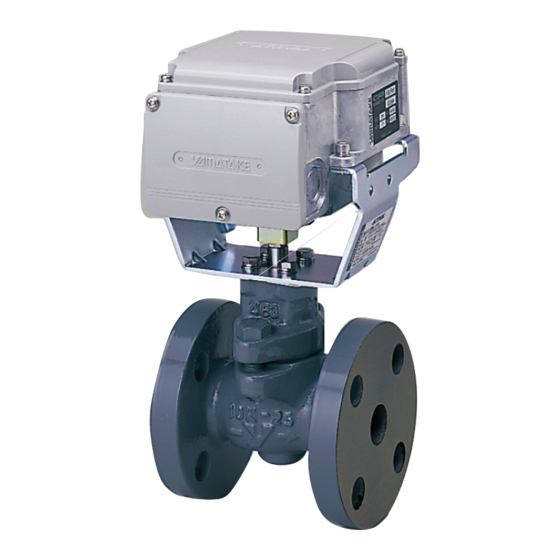
Motorized Two-Way Valve with Flanged-End Connection
„ Overview
ACTIVAL
TM
Model VY51_ _J is a series of motorized two-
way valves with flanged-end connection. Rotary valve and
actuator are integrated in a single unit.
The valve body rating corresponds to ANSI Class 125.
Actuator has a reversible synchronous motor, which operates
at a low voltage of 24 V AC.
Two kinds of control signals are available to operate the
ACTIVAL.
1. 4–20 mA DC input
2. 2–10 V DC input
Both provide proportional control in combination with a
single loop controller (e.g., Model SDC35/SDC36).
„ Features
Compact and lightweight:
•
Rotary motor actualizes small body and light weight.
NEMA 4X Enclosure
•
•
Valve and actuator integrated in a single unit:
Pre-assembled body requires no adjustment.
A variety of control signals available:
•
- 4–20 mA DC input
- 2–10 V DC input
Valve for chilled/hot water control and for steam control
•
applicable to high differential pressure, large Cv value,
high rangeability, and low leakage.
Durable actuator with low power consumption.
•
•
Equal percentage flow characteristics.
2–10 V DC output (for position feedback) available with
•
2–10 V DC input type.
4–20 mA DC output (for position feedback) available with
•
4–20 mA DC input type.
ACTIVAL
(ANSI Class 125 / A126 Class B)
TM
For 4–20 mA Model
Open/close changeover for input signal failure:
•
Actuator fully opens/closes valve in case that the control
signal is not input to the actuator. (Default: Fully open)
Direction changeover of control action:
•
Open/close action by 4 to 20 mA DC input signal is
reversely controllable.
Normal action 4 mA: 0 % to 20 mA: 100 %
Reverse action 20 mA: 0 % to 4 mA: 100 %.
(Default: Normal action)
•
Adjustable dead band*:
Dead band width can be narrowed to more precisely
operate valve actuator.
* Actuator is not operated by input signal changed less than a
certain amount. This amount of change is called dead band.
© 2018 Azbil Corporation All Rights Reserved.
1
AB-7489-U
Specifications/Instructions
Advertisement

Subscribe to Our Youtube Channel
Related Manuals for Azbil Actival VY51 Series


Summary of Contents for Azbil Actival VY51 Series
- Page 1 2–10 V DC output (for position feedback) available with certain amount. This amount of change is called dead band. • 2–10 V DC input type. 4–20 mA DC output (for position feedback) available with • 4–20 mA DC input type. © 2018 Azbil Corporation All Rights Reserved.
-
Page 2: Safety Precautions
like, or with 2 or more people. Azbil Corporation bears no responsibility for any Careless lifting or accidental dropping of the result, or lack of result, deriving from the product may result in injury or product customer’s use of the product. - Page 3 AB-7489-U CAUTION CAUTION After installation, make sure no fluid leaks Use crimp terminals with insulation for from the valve-pipe connections. connections to the product terminals. Improper piping may cause fluid leakage Failure to do so may cause short circuit outside of the valve.
- Page 4 AB-7489-U „ Specifications For weight, refer to the table shown in the section Dimensions. Valve specifications Item Specification Model Two-way valve with flanged-end connection, proportional control Body pressure rating ANSI Class 125 End connection ANSI Class 125 bolt pattern flanges, flat face flange (FF) Size, Cv, Close-off ratings Nominal size Model number...
- Page 5 AB-7489-U Valve and actuator (as a single unit) specifications Item Specification Environmental conditions Transport/storage Rated operating condition Limit operating condition conditions (packaged* Ambient temperature* -4 to 122 °F (-20 to 50 °C) -4 to 140 °F -4 to 158 °F (Fluid temperature 32 to 302 °F (-20 to 60 °C) (-20 to 70 °C)
- Page 6 AB-7489-U „ Dimensions 2.76" 2.76" Min. 12" 3.23" 3.35" (70 mm) (70 mm) (305 mm) (82 mm) (85 mm) Min. 20" (508 mm) (See Note.) N × h Dia. ∗ Note: Leave a clearance of 4" (100 mm) if you do not open the top cover (to set the selector switches after the ACTIVAL is installed).
- Page 7 AB-7489-U „ Setting For 4–20 mA model On the PCB (printed circuit board) of the actuator, the selector switches are provided. CAUTION Before beginning setup work, be sure to turn off the power to this product. Failure to do so may result in electric shock or device failure. After changing the settings, be sure to reattach the terminal cover.
-
Page 8: Incorrect Mounting
AB-7489-U „ Installation Precautions for installation WARNING When handling or transporting any heavy product (more than 39.7 lb (18 kg)), carefully move the product with a handtruck or the like, or with 2 or more people. Careless lifting or accidental dropping of the product may result in injury or product damage. ... - Page 9 AB-7489-U Piping CAUTION When installing this product, hold it in the proper position and securely fasten it to the pipes. Excessive tightening or improper installation position may damage the valve. • Check that the model number of the product is what you ordered. The model number is shown on the label attached to the yoke.
- Page 10 AB-7489-U Manually opening/closing the ACTIVAL IMPORTANT: • Manually opening/closing the ACTIVAL with the power (24 V AC) applied might damage the actuator. • To manually open/close the ACTIVAL, do not turn the joint beyond the fully open (100)/closed (0) mark. •...
- Page 11 AB-7489-U Procedure to change the actuator mounting position IMPORTANT: • Do not change the combination of the valve, yoke, and actuator. • Set the ACTIVAL in 100 % position when changing the mounting position. If the valve in 0 % position is assembled with the actuator in 100 % position, the actuator put torque on the closed valve, and the gear of the actuator gets damaged.
- Page 12 AB-7489-U „ Wiring CAUTION Provide a circuit protector (e.g., a fuse or circuit breaker) for the power source. Failure to do so may cause a short circuit leading to fire or device failure. Install, wire, and use this product under the conditions specified by this manual. ...
- Page 13 AB-7489-U 2) Unscrew the 3 setscrews (M4 × 10) of the terminal cover and remove the terminal cover, as shown in Fig. 9. Setscrews Terminal cover 1. Unscrew the setscrews. 2. Remove terminal cover. Figure 9. Terminal cover removal 3) Correctly connect the wires to the terminals with M3.5 screw terminal lugs, referring to Figs 10 to 15. 4) Attach the terminal cover by the 3 original screws.
- Page 14 AB-7489-U Connection Examples (Connection to Azbil Corporation’s SDC series controller) <2–10 V DC input> Connection to Model SDC35TD0/SDC36TD0 Connection to Model SDC35TD0/SDC36TD0 (Parallel operation) Isolation Isolation transformer transformer Power Power supply supply + 13 + 13 Model Model SDC35TD0/SDC36TD0...
- Page 15 AB-7489-U <4–20 mA DC input> Connection to Model SDC35TC0/SDC36TC0 Connection to Model SDC35TC0/SDC36TC0 (Parallel operation) Isolation Isolation transformer transformer Power Power supply supply + 13 + 13 Model Model SDC35TC0/SDC36TC0 SDC35TC0/SDC36TC0 Isolator Position indicator Isolator Position indicator Model VY519_J (4 to 20 mA DC input with 4 to 20 mA DC output) Isolation transformer...
- Page 16 Visually inspect the fluid leakage of the valve and the actuator operations every six months. If any of the problems • described in Table 2 are found, take corresponding actions shown in the table. If your problem is not solved by the corresponding action, please contact Azbil Corporation near you. Table 1. Inspection items and details Inspection item...
- Page 17 AB-7489-U Table 2. Troubleshooting Problem Part to check Action Fluid leaks from the flange face. Loosened flange bolts Tighten the flange bolts. Gasket on the flange face Replace the gasket. Misaligned piping Redo piping. Fluid leaks from the gland part. Consult with our sales personnel.
- Page 18 AB-7489-U This blank page was added for page layout purposes.
- Page 19 AB-7489-U This blank page was added for page layout purposes.
- Page 20 EN 55011 Class A, Group 1 RoHSD: EN 50581 9033 N. 24th Ave., Suite 6 Phoenix, AZ 85021 888-262-4639 Building Systems Company 602-216-8199 1-12-2 Kawana, Fujisawa, Kanagawa 251-8522 JAPAN http://us.azbil.com/ http://www.azbil.com/ AB-7489-U Specifications are subject to change without notice. Rev. 0.0 Mar. 2018...
Need help?
Do you have a question about the Actival VY51 Series and is the answer not in the manual?
Questions and answers