Husqvarna Rider 15V2 Operator's Manual
Hide thumbs
Also See for Rider 15V2:
- Workshop manual (79 pages) ,
- Operator's manual (55 pages) ,
- Operator's manual (40 pages)

Related Manuals for Husqvarna Rider 15V2


Summary of Contents for Husqvarna Rider 15V2
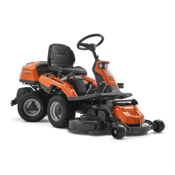
- Page 1 Operator´s manual Rider 15V2 Rider 15V2 AWD Please read these instructions carefully and make sure English you understand them before using the machine.
-
Page 3: Table Of Contents
CONTENTS Operator’s Manual for Rider 15V2 and Rider 15V2 AWD Introduction ............2 Checking and adjusting the throttle wire ..27 Travel and transport on public roads ....2 Checking and adjusting the choke wire ..27 Towing .............. 2 Inspecting the muffler ........ -
Page 4: Introduction
INTRODUCTION Dear customer Thank you for choosing a Husqvarna Rider. Husqvarna Riders are built to a unique design with a frontmounted cutting unit and a patented rear-wheel steering system. Riders are designed for maximum efficiency even in small or confined areas. Collected controls and a hydrostatic transmission controlled by pedals also contribute to the machine’s performance. -
Page 5: Serial Number
INTRODUCTION Good service Husqvarna products are sold all over the world and only through servicing dealers. This is to ensure that you, the customer, get the best support and service. When you need spare parts or advice on service issues, warranty terms, etc., contact: This Operator’s Manual belongs to... -
Page 6: Explanation Of Symbols
EXPLANATION OF SYMBOLS These symbols are on the machine and in the operator’s manual. Study them carefully so that you know what they mean. Read the operator’s manual Neutral Fast Slow Engine off Choke Fuel Oil level Cutting height Backwards Forwards Ignition Hydrostatic free wheel... -
Page 7: Safety Instructions
SAFETY INSTRUCTIONS Safety instructions These instructions are for your safety. Read them carefully. WARNING! The inserted symbol means that important safety instructions need to be observed. It applies to your safety. General use • Read all the instructions in this operator’s manual and on the machine before you start it. - Page 8 SAFETY INSTRUCTIONS • Take care when rounding a fixed object, so that WARNING! the blades do not hit it. Never run the machine Engine exhaust, some of its over foreign objects. constituents and certain vehicle components contain or emit • Only use the machine in daylight or in other chemicals considered to cause well-lit conditions.
-
Page 9: Driving On Slopes
SAFETY INSTRUCTIONS Driving on slopes Driving on slopes is one of the operations where the risk of the driver losing control of the machine or of it overturning is the greatest; this can result in serious injury or death. All slopes demand extra care. -
Page 10: Children
SAFETY INSTRUCTIONS Children Serious accidents may occur if you fail to be on your guard for children in the vicinity of the machine. Children are often attracted to the machine and mowing. • Never assume that children will remain where you last saw them. - Page 11 SAFETY INSTRUCTIONS • If leaks arise in the fuel system, the engine must not be started until the problem has been resolved. • Store the machine and fuel in such a way that there is no risk that leaking fuel or fumes can cause any damage.
-
Page 12: Transport
SAFETY INSTRUCTIONS • Never use the machine indoors or in spaces lacking proper ventilation. Exhaust fumes contain carbon monoxide, an odourless, poisonous and highly dangerous gas. • Stop and inspect the equipment if you run over or into anything. If necessary, make repairs before starting. -
Page 13: Presentation
This operator’s manual describes Rider 15V2 and Rider 15V2 AWD. The machines are equipped with There is one pedal for driving forwards and one a 15 horse power engine from Kawasaki. -
Page 14: Throttle Control
PRESENTATION Throttle control The throttle control regulates the engine speed, and thereby also the rotation speed of the blades. To increase or reduce the engine speed the control is moved forwards or backwards. Avoid idling the engine for long periods, as there is a risk of carbon build-up on the spark plugs. -
Page 15: Cutting Unit
PRESENTATION Cutting unit Rider 15V2 and Rider 15V2 AWD can be equipped with two different cutting units. Combi 1030 mm/41" Combi 1120 mm/44" See “Maintenance \ Checking the Blades” for identification of the cutting unit. The combi deck functions as a mulching deck when a bio-clip plug is mounted. -
Page 16: Lever For Adjustment Of Cutting Height
PRESENTATION Lever for adjustment of cutting height With this lever the cutting height can be adjusted to 9 different positions. Combi unit 40-90 mm (1 9/16" - 3 9/16") Seat The seat has a jointed attachment on the front edge and can be tipped forward. The seat can also be adjusted lengthways. -
Page 17: Driving
1. Lift up the cutting unit by pulling the lever backwards to locked position (transport posi- tion) and apply the parking brake. Rider 15V2 AWD The engine can not be started if the parking brake is not pressed down. 2. Move the throttle control to the middle position. - Page 18 DRIVING 5. When the engine starts release the ignition key immediately back to neutral position. IMPORTANT INFORMATION Do not run the starter for more than about 5 seconds at a time. If the engine does not start, wait about 15 seconds before trying again.
-
Page 19: To Start An Engine With A Weak Battery
DRIVING To start an engine with a weak battery WARNING! Lead-acid batteries generate explosive gases. Keep sparks, flame and smoking materials away from batteries. Always wear eye protection when around batteries. If your battery is too weak to start the engine, it should be recharged. -
Page 20: Driving The Machine
DRIVING Driving the machine 1. Release the parking brake by pressing down the parking brake pedeal and then releasing it. 2. Carefully press down one of the pedals until the correct speed is reached. To drive forwards: press down pedal (1). To reverse: press down pedal (2). -
Page 21: Cutting Tips
DRIVING 4. Push in the lock button on the lift lever and lower down the cutting unit. IMPORTANT INFORMATION The service-life of the drive belts increases considerably if the engine is run at low speed when engaging the blades. For this reason do not increase the throttle until the cutting unit has been lowered to the cutting position. -
Page 22: Stopping The Engine
DRIVING WARNING! Never drive the machine on ground with a slope of more than 15°. Mow slopes upwards and downwards, never across. Avoid sudden changes in direction. MAX 15 Stopping the engine Preferably allow the engine to idle for a minute to obtain normal working temperature before stopping it if it has been working hard. -
Page 23: Release Lever
Rider to be moved when the engine is shutoff. Rider 15V2 Release lever Rider 15V2 AWD Rider 15V2 AWD has one control for the front axle and one control for the rear axle. Pull the controls to their end positions. Do not use an intermediate position. -
Page 24: Maintenance
200 hours. Replace the paper element yearly or every 200 hours. Conducted by an authorised service workshop. Rider 15V2 AWD only. Replace first after 8 hours. = Described in these instructions. = Not described in these instructions. -
Page 25: Cleaning
MAINTENANCE Cleaning Clean the machine directly after use. It is much easier to wash off grass cuttings before they dry. Oily dirt can be removed using a cold degreasing agent. Spray on a thin layer. Rinse at normal water pressure. Do not direct the jet towards electrical components or bearings. -
Page 26: Removing The Machine Hoods
MAINTENANCE Removing the machine hoods Engine hood The engine is accessible for servicing when the engine hood is lifted up. Tilt the seat forward, release the rubber strap under the seat, and tilt the hood backwards. Front hood Release the clip on the front hood and lift off the hood. -
Page 27: Checking And Adjusting Of The Steering Wires
MAINTENANCE Checking and adjustment of the steering wires The steering is controlled by means of wires. These can in time become slack, which implies that the adjustment of the steering becomes altered. Check and adjust the steering as follows: 1. Dismantle the frame-plate by releasing the screws (two on each side). -
Page 28: Adjusting The Parking Brake
MAINTENANCE Adjusting the parking brake Rider 15V2 The parking brake is adjusted as follows: 1. Loosen the locking nuts (1). 2. Tension the cable using the adjuster screw (2) until the play in the cable is taken up. 3. Tighten the locking nuts (1). -
Page 29: Checking And Adjusting The Throttle Wire
MAINTENANCE Checking and adjustment of the throttle wire Check that the engine responds to the throttle control and that the correct engine speed is achieved at full throttle. If in doubt, contact the service workshop. If adjustment is necessary, adjust the lower wire as follows: 1. -
Page 30: Replacing The Fuel Filter
MAINTENANCE Replacing the fuel filter Replace the pipe fitted fuel filter every 100 running hours (once per season) or more frequently if it is clogged. Replace the filter as follows: 1. Fold open the engine cover. 2. Move the hose clips away from the filter. Use a pair of flat pliers. -
Page 31: Checking Of The Fuel Pump's Air Filter
MAINTENANCE 5. Clean the paper element by tapping gently to remove dust. If the element is very dirty, replace it with a new one. Always replace the paper element every 200 hours. 6. Reinstall the foam element and the paper element into the air cleaner case. -
Page 32: Ignition System
MAINTENANCE Ignition system The engine is equipped with an electronic ignition system. Only the spark plugs require maintenance. For recommended spark plug, see chapter ”Technical data”. IMPORTANT INFORMATION Fitting the wrong spark plug type can damage the engine. 1. Remove the ignition cable shoe and clean around the spark plug. 2. -
Page 33: Inspecting The Safety System
Does not work conditions and try again. Check that the engine stops if you temporarily move out off the driver’s seat while the cutting unit is lowered or the hydrostat pedals are not in the neutral position. Rider 15V2 English –... - Page 34 Does not work conditions and try again. Check that the engine stops if you temporarily move out off the driver’s seat while the cutting unit is lowered or the hydrostat pedals are not in the neutral position. Rider 15V2 AWD – English...
-
Page 35: Main Fuse
MAINTENANCE Main fuse The fuse is located in a loose holder under the battery case cover, in front of the battery. Type: Flat-blade U-link, 15 A. Do not use any other type of fuse when replacing. A blown fuse indicates that the U-link has burnt off. Pull the fuse out of the holder when replacing. -
Page 36: Fitting The Cutting Unit
MAINTENANCE Fitting the cutting unit WARNING! Wear protective glasses when fitting the cutting unit. The collet spring which tensions up the belt can go off and cause personal injury. 1. Place the Rider on a flat surface and apply the parking brake. -
Page 37: Removing The Cutting Unit
MAINTENANCE 6. Move the support wheels to their parking position. 7. Fit the front cover. 8. Secure the collet spring. Removing the cutting unit WARNING! Wear protective glasses when removing the cutting unit. The collet spring which tensions up the belt can go off and cause personal injury. -
Page 38: Checking And Adjusting The Cutting Unit's Ground Pressure
MAINTENANCE Checking and adjusting the cutting unit’s ground pressure To achieve the best cutting results the cutting unit should follow the underlying surface without pressing too hard against it. The pressure is adjusted with a screw on each side of the machine. 1. -
Page 39: Checking The Cutting Unit's Parallelism
MAINTENANCE Checking the cutting unit’s parallelism Check the parallelism of the cutting unit as follows: 1. Check the air pressure in the tyres 60 kPa (0.6 kp/cm /8.5 PSI). 2. Place the machine on a level surface. 3. Put the lifting lever in the mowing position. 4. -
Page 40: Service Position For The Cutting Unit
MAINTENANCE Service position for the cutting unit The cutting head can be placed in the service position to provide easy access for cleaning, repairs and servicing. In the service position the cutting unit is raised and locked in the vertical position. Placing in service position 1. - Page 41 MAINTENANCE 4. Fit the support wheels on either side of the rear of the cutting unit. WARNING! Wear protective glasses when dismantling the cutting unit. The spring which tensions up the belt can go off and cause personal injury. 5. Disengage the spring for the drive belt tensioning wheel.
- Page 42 MAINTENANCE WARNING! Observe caution to avoid trapping your hand. 8. Lift off the drive belt (1). Then pull out the pin (2). 9. Pull the frame forwards and refit the pin. 10.Grasp the front edge of the cutting unit, pull out and raise into the service position.
-
Page 43: Checking The Blades
MAINTENANCE Checking the blades To achieve the best mowing results it is important that the blades are undamaged and well-sharpened. Check that the blades’ attachment screws are tight. IMPORTANT INFORMATION Replacing or sharpening the blades should be conducted by an authorised service workshop. -
Page 44: Lubrication
LUBRICATION Checking the engine’s oil level Check the oil level in the engine when the Rider stands horizontal and the engine is switched off. Fold open the engine cover. Release the dip stick and pull out. Wipe off the oil and insert again without screwing it in. -
Page 45: Changing The Oil
LUBRICATION Changing the oil The oil should be changed for the first time after 8 hours of running time. Thereafter it should be changed every 100 hours of running time. With heavy loads or high temperatures replace the oil after every 50 hours. WARNING! Engine oil can be very hot if it is drained off directly after the... -
Page 46: Checking The Transmission's Oil Level
2. Check that there is oil in the transmission’s oil tank. Fill if necessary with engine oil. Rider 15V2: SAE 10W/30 (class SF–CC) Rider 15V2 AWD: SAE 10W/30 (class SF–CC) The oil should be changed by an authorised service workshop, and is described in the Workshop Manual. -
Page 47: Trouble Shooting Schedule
TROUBLE SHOOTING SCHEDULE Problem Procedure Engine will not start. • Fuel tank empty. • Spark plug defective. • Spark plug connection defective. • Dirt in carburettor or fuel pipe. • Starter does not pull round engine. Starter does not pull round engine. •... -
Page 48: Storage
STORAGE To put the machine in order for storage follow these Winter storage instructions: At the end of the season the machine should 1. Carefully clean the machine, especially under immediately be put in order for storage, also if it is the cutting unit. -
Page 49: Technical Data
TECHNICAL DATA Dimensions Rider 15V2 Rider 15V2 AWD Length without unit 2020 mm / 6.61 ft 2020 mm / 6.61 ft Width without unit 880 mm / 2.89 ft 880 mm / 2.89 ft Height 1070 mm / 3.52 ft 1070 mm / 3.52 ft... -
Page 50: Eu Declaration Of Conformity
Husqvarna AB, SE-561 82 Huskvarna, Sweden, tel: +46-36-146500, declares under sole responsibility that Husqvarna Rider 15V2 and Rider 15V2 AWD, from 2005’s serial numbers and onwards (the year is clearly stated in plain text on the rating plate with subsequent serial number), complies with the requirements of the COUNCIL’S DIRECTIVES: - of June 22, 1998 ”relating to machinery”... -
Page 51: Service Journal
SERVICE JOURNAL Date, mileage, stamp, sign Work done Pre-delivery service 1. Top up battery with acid and recharge for four hours. 2. Fit steering wheel, seat and any optional equipment. 3. Adjust cutting unit: Adjust the lifting springs (the “weight” of the cutting unit should be 12-15 kg/26,5-33 lbs). - Page 52 SERVICE JOURNAL Work done Date, mileage, stamp, sign – English...
- Page 53 SERVICE JOURNAL Work done Date, mileage, stamp, sign English –...
- Page 54 SERVICE JOURNAL Work done Date, mileage, stamp, sign – English ´®z+R26¶6f¨...
- Page 56 115 01 82-26 ´®z+R26¶6f¨ 2005W47...
Need help?
Do you have a question about the Rider 15V2 and is the answer not in the manual?
Questions and answers