
Related Manuals for Husqvarna Rider 15V2s AWD


Summary of Contents for Husqvarna Rider 15V2s AWD
- Page 1 Rider 15V2 Rider 15V2 AWD Rider 15V2s AWD Please r ead the operator’s manual carefully and make sure you E E E E n n n n g g g g l l l l i i i i s s s s h h h h...
-
Page 2: Table Of Contents
Contents CONTENTS Contents ... Ser vice journal Pre-deliv ery service ... After the first 8 hours ... INTR ODUCTION Dear Customer , ... Driving and transport on public roads ... Towing ... Use ... Good service ... Serial Number ... KEY TO SYMBOLS Symbols ... -
Page 3: Ser Vice Journal
Pre-deliver y service 1 1a. Dry-charged battery (506788801) Fill the battery with battery acid and charge for 4 hours at max. 6 amp. 1b. Wet-charged battery (510138501) Charge the battery for 4 hours at max. 3 amp. 2 Fit steering wheel, seat and any optional equipment. 3 Check and adjust tyre pressure (60 Kpa, 0.6 bar, 9 PSI). -
Page 4: Intr Oduction
Dear Customer , Thank y ou for choosing a Husqvarna Rider. Husqvarna Riders are built to a unique design with a front-mounted cutting unit and a patented rear-wheel steering system. Riders are designed for maximum efficiency even in small or confined areas. The closely grouped controls and pedal-operated hydrostatic transmission also contribute to the performance of this machine. -
Page 5: Good Service
Good ser vice Husqv arna products are sold all over the world and only through servicing dealers. This is to ensure that you, the customer, get the best support and service. For example, before this machine was delivered it was inspected and adjusted by your dealer. See the certificate in the Service Journal in this manual. -
Page 6: Key To Symbols
Symbols These symbols are on the machine and in the instr uctions. WARNING! Careless or incorrect use can result in serious or fatal injury to the operator or others. Please read the operator’s manual carefully and make sure you understand the instructions before using the machine. - Page 7 KEY T O SYMBOLS Chec k the engine’s oil level Check transmission oil level Lift up the cutting unit Apply the parking brake. If the engine is cold, use the choke Release the parking brake before driving – 7 English...
-
Page 8: Safety Instr Uctions
SAFETY INSTR UCTIONS Saf ety instructions These instr uctions are for your safety. Read them carefully. Insure y our Rider • Check the insurance coverage for your new Rider. • Contact your insurance company. • You should have fully comprehensive insurance including: third party, fire, damage, theft and liability General use •... -
Page 9: Driving On Slopes
SAFETY INSTR UCTIONS • Never allow children or other persons not trained in the use of the machine to use or service it. Local laws may regulate the age of the user. W ARNING! You must use approved personal protective equipment whenever you use the machine. -
Page 10: Children
SAFETY INSTR UCTIONS • Follow the manufacturer’s recommendations regarding wheel weights or counterbalance weights to increase machine stability. IMPORTANT INFORMATION Wheel weights fitted on the rear wheels are recommended when driving on slopes for safer steering and improved manoeuvrability. Consult your dealer concerning the use of wheel weights if you are unsure. -
Page 11: Transport
SAFETY INSTRUCTIONS • Make sure all nuts and bolts are tightened correctly and that the equipment is in good condition. • Do not modify safety equipment. Check regularly to be sure it works properly. The machine must not be driven if protective plates, protective covers, safety switches or other protective devices are not fitted or are defective. -
Page 12: What Is What
Location of the controls 1 Choke control 2 Switch for the lights 3 Throttle control 4 Ignition lock 5 Counter 6 Cutting height adjustment lever 7 Lifting lever for the cutting unit 8 Speed limiter for reversing 12 – English WHAT IS WHAT? 9 Speed limiter for driving forward 10 Parking brake... -
Page 13: Presentation
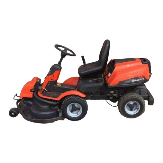
Congratulations on your choice of an excellent quality product that will give you great pleasure for many years. This operator’s manual describes Rider 15V2, Rider 15V2s AWD and Rider 15V2 AWD. The machines are equipped with a 15 horse power engine from Kawasaki. -
Page 14: Cutting Unit
Cutting unit Rider 15V2, Rider 15V2s AWD and 15V2 AWD can be equipped with two different cutting units. • Combi 1030mm/41” • Combi 1120 mm/44” The Combi-unit, equipped with a BioClip-plug, finely chops the cuttings to fertiliser. Without the BioClip-plug the unit works in the same way as a rear ejection unit. -
Page 15: Fuelling
The seat can also be adjusted lengthways. To adjust move the lever under the front edge of the seat to the left, so that the seat can be moved forward or backwards to the required position. Fuelling The engine runs on unleaded petrol with a minimum octane rating of 87 (not mixed with oil). -
Page 16: Driving
Before starting • Read the safety instructions and information concerning the placement of controls and functions before starting. • Perform daily maintenance before starting as set out in the Maintenance schedule. IMPORTANT INFORMATION The air intake grille in the engine cover behind the driver’s seat must not be blocked by, for example, clothing, leaves, grass or dirt. -
Page 17: Starting The Engine With A Weak Battery
8 Let the engine run at moderate speed or half throttle for 3- 5 minutes before subjecting it to heavy load. 9 Set the required engine speed with the throttle control. WARNING! Never run the engine indoors, in enclosed or poorly ventilated areas. The exhaust fumes contain toxic carbon monoxide. -
Page 18: Cutting Tips
4 Press in the lock button on the lifting lever and lower the cutting unit. IMPORTANT INFORMATION The life span of the drive belts is increased significantly if the engine runs at a low speed when the blades are engaged. Therefore apply full throttle first when the cutting unit has been moved to the mowing position. -
Page 19: Maintenance
Maintenance schedule The following is a list of the maintenance which should be conducted on the machine. For those points not described in this manual, visit an authorised service workshop. Maintenance Cleaning Check the engine’s oil level Check the engine’s cooling air intake Check the fuel pump air filter Check the steering wires Check the battery... -
Page 20: Cleaning
Cleaning Clean the machine directly after use. It is much easier to wash off grass cuttings before they dry. Oily dirt can be removed using a cold degreasing agent. Spray on a thin layer. Rinse at normal water pressure. Do not direct the jet towards electrical components or bearings. -
Page 21: Adjusting The Parking Brake Rider 15V2
1 Remove the frame plate by loosening the screws (2) and lift the frame plate by the rear edge. 2 Check the tension of the steering wires by squeezing them together by the arrows as illustrated. It should be possible to push them together so that the distance between them is half as much, without using unnecessary force. -
Page 22: Checking And Adjusting The Choke Wire
1 Loosen the clamping screw for the cable’s outer casing and move the throttle to the full throttle position. 2 Check that the throttle wire is attached to the correct hole in the lower lever, see diagram. 3 Pull the throttle wire casing to the far left and tighten the clamping screw. -
Page 23: Checking The Fuel Pump's Air Filter
Always replace the paper filter every 200 hours. 7 Put the pre-filter and paper filter back into the air filter unit. 8 Put back the air filter unit by first aligning the hooks on the bottom of the unit, then press it until the catches lock into position. -
Page 24: Check The Safety System
Check that the engine stops if you temporarily move out off the driver’s seat while the cutting unit is lowered or the hydrostat pedals are not in the neutral position. Rider 15V2 Rider 15V2 AWD, Rider 15V2s AWD 24 – English Maintenance... -
Page 25: Replacing The Light Bulbs
Replacing the light bulbs For information about the bulb type, see Technical Data. 1 Loosen the lock nut and remove the Allen bolt. Remove the steering wheel. 2 Unscrew the two screws holding the cover on the power servo housing. One screw on each side. 3 Press in the parking lock button and lift the cover over the steering column. -
Page 26: Checking The Engine's Cooling Air Intake
Checking the engine’s cooling air intake Clean the air intake grille in the engine cover behind the driver’s seat. Open the engine cover. Check that the cooling intake is free from leaves, grass and dirt. Check the air duct, located on the inside of the engine cover, ensure it is clean and does not rub against the cooling air intake. -
Page 27: Removing The Cutting Unit
7 Slide the unit in and insert the pin. Make sure that the tongue (3) on the cutting unit engages correctly. 8 Fit the drive belt around the drive wheels of the cutting unit. 9 Hook up the height adjustment strut. 10 Move the support wheels to their parking position. -
Page 28: Checking The Cutting Unit's Parallelism
5 Adjust the unit’s ground pressure by screwing in or out the adjusting screws located behind the front wheels on both sides. The ground pressure should be between 12 and 15 kg (26.5-33 lb). Checking the cutting unit’s parallelism Check the cutting unit’s parallelism as follows: 1 Check the air pressure in the tyres 60 kPa/0.6 kp/cm PSI. -
Page 29: Placing In The Service Position
Placing in the service position 1 Position the machine on flat ground. Apply the parking brake. Adjust the cutting unit to the lowest cutting height and lower the cutting unit. 2 Remove the front hood by removing the pin. (There are complete instructions on using the service position inside the front hood). -
Page 30: Restoring From Service Position
8 Lift of the drive belt. Then pull out the pin. 9 Pull the frame forwards and refit the pin. 10 Grasp the front edge of the cutting unit, pull out and raise into the service position. If the cylindrical bolt, which is now holding the cutting unit is removed, the cutting unit can be lifted off. -
Page 31: Checking The Engine's Oil Level
Checking the engine’s oil level. Check the oil level in the engine when the Rider stands horizontal with the engine switched off. Open the engine cover. Loosen the dipstick, pull it up and wipe it off. Now insert the dipstick again, without tightening it. Pull the dipstick out again and read the oil level. -
Page 32: Checking The Transmission Oil Level
Fill with new oil according to Checking the engine’s oil level. Start the engine and let it idle for about 3 minutes. Now stop it and check for signs of leakage. Fill with oil to compensate for the oil held in the new oil filter. Checking the transmission oil level 1 Remove the transmission cover. -
Page 33: Troubleshooting Schedule
Troubleshooting schedule Problem Engine does not start Starter motor does not turn over the engine Battery flat Engine does not run smoothly Engine seems to have no power Engine overheats Battery does not charge Machine vibrates Uneven mowing Procedure There is no fuel in the fuel tank Spark plug defective Faulty spark plug connections or interchanged cables Dirt in the carburettor or fuel line... -
Page 34: Storage
Winter storage At the end of the season, or if the machine is going to stand idle for more than 30 days, it should immediately be made ready for storage. Fuel which is left to stand for long periods (30 days or more) can leave tacky deposits which can block the carburettor and interfere with the engine. -
Page 35: Technical Data
1120/44 (Combi 112) 1120/44 (Combi 112) 40-90/1 9/16-3 9/16 40-90/1 9/16-3 9/16 390/15 3/8 (Combi 103) 390/15 3/8 (Combi 103) 420/16 1/2 (Combi 112) 420/16 1/2 (Combi 112) Rider 15V2s AWD 2020/6,61 880/2,89 1070/3,52 312-315 / 688-694 855/2,8 715/2,37 625/2,05... -
Page 36: Ec-Declar Ation Of Conformity
Husqvarna AB, SE-561 82 Huskvarna, Sweden, tel.: +46-36-146500, hereby declares that Husqvarna Rider 15V2, Rider 15V2 AWD and Rider 15V2s AWD from 2008’s serial numbers and onwards (the year is clearly stated in plain text on the rating plate with subsequent serial number), complies with the requirements of the COUNCIL’S DIRECTIVE: of June 22, 1998 ”relating to machinery”... - Page 38 ´®z+S!r¶6H¨ ´®z+S!r¶6H¨...
- Page 40 1151018-26 ´®z+S!r¶6H¨ ´®z+S!r¶6H¨ 2009-05-11...
Need help?
Do you have a question about the Rider 15V2s AWD and is the answer not in the manual?
Questions and answers