
Related Manuals for Husqvarna 14 Pro


Summary of Contents for Husqvarna 14 Pro
- Page 1 Rider 14 Pro Operator´s manual Please read these instructions carefully and make sure you understand them before using the machine. 101 90 55-95...
- Page 2 Svenska –...
-
Page 3: Table Of Contents
For servicing other than described in this manual contact an authorised dealer for parts and service. CONTENTS Operator’s Manual for Rider 14 Pro Checking the transmission’s air intake ... 20 Checking the transmission’s oil level ... 20 Checking and adjusting the steering wires ... 21 Adjusting the brakes ... -
Page 4: Safety Instructions
Safe operation practices for ride-on mowers IMPORTANT! This cutting machine is capable of amputating hands and feet and throwing objects. Failure to ob- serve the following safety instructions could result in serious injury or death. General operation 1. Read, understand and follow all instructions in the manual and on the machine before start- ing. - Page 5 SAFETY INSTRUCTIONS IV. Service 1. Use extra care in handling gasoline and other fuels. They are flammable and vapours are explosive. a) Use only an approved container. b) Never remove gas cap or add fuel with the engine running. Allow engine to cool before refuelling.
-
Page 6: Explanation Of Symbols
EXPLANATION OF SYMBOLS These symbols are on the machine and in the instructions. Study them carefully so that you know what they mean. Reverse Neutral Oil pressure Cutting height Use hearing protection Warning! Rotating blades Sound level Never use the machine if persons, especially children, or animals, are in the vicinity –... -
Page 7: Safety Instructions
SAFETY INSTRUCTIONS These instructions are for your safety. Read them carefully. This symbol implies that important safety rules are applicable. This is for your safety and the operating reliability of the machine. General use: • Make yourself familiar with the controls and how to stop quickly. -
Page 8: Driving On Slopes
Do not try to stabilise the machine by placing one foot on the ground. • The Rider lawn mower must never be driven close to an edge or ditch when cleaning the chassis. Be extra careful when driving on slopes. -
Page 9: Children
SAFETY INSTRUCTIONS Children Tragic accidents can occur if the driver does not pay attention to children in the vicinity. Children are often attracted to the machine and the work of mowing. Never assume that children stay where you last saw them. •... - Page 10 • Be careful with the maintenance of the battery. Explosive gas is formed in the battery. Never handle the battery when smoking or in the vicinity of naked flames or sparks. Otherwise the battery can explode and cause severe injuries. •...
-
Page 11: Presentation
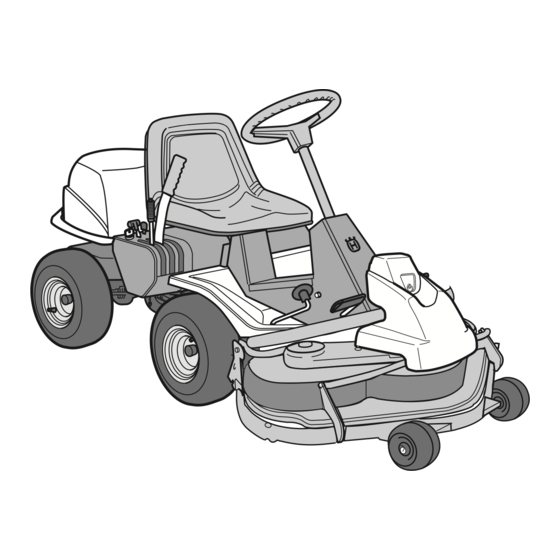
Congratulations on choosing an excellent quality product, Rider ProFlex. These instructions describe the Rider 14 Pro. The Rider 14 Pro is equipped with a 14 horsepower Vanguard V-Twin engine from Briggs & Stratton. Location of the controls 1. Ignition lock 2. -
Page 12: Throttle Control
PRESENTATION Throttle control The throttle control regulates the engine speed, and thereby also the rotation speed of the blades. To increase or reduce the engine speed the control is moved forwards or backwards. Choke lever The choke lever is used for cold starting and to give the engine a richer fuel mixture. -
Page 13: Cutting Unit
Cutting unit Rider 14 Pro can be equipped with numerous attachments. The BioClip unit finely cuts the lawn by cutting the grass several times before returning the clippings to the lawn as fertiliser. The cutting unit with side or rear ejection, that is, the clippings are ejected to the side or behind the unit. -
Page 14: Lever For Adjustment Of Cutting Height
Lever for adjustment of the cutting height The cutting height can be adjusted to 9 different positions with the cutting height lever. Cutting unit with side/rear ejector, BioClip cutting unit, Parking brake The parking brake is applied as follows: 1. Push down the brake pedal (1). 2. -
Page 15: Driving
Before starting • Read the safety instructions and information on the location and function of the controls before starting (see pages 5–12). • Conduct daily maintenance before starting (see maintenance schedule on page 17). • Adjust the seat to the required position. Starting the engine 1. -
Page 16: Driving The Machine
5. When the engine starts release the ignition key immediately back to neutral position. IMPORTANT INFORMATION Do not run the starter for more than about 5 seconds at a time. If the engine does not start, wait about 10 seconds before trying again. -
Page 17: Cutting Tips
3. Push in the lock button on the lift lever and lower down the cutting unit. 4. Select the required cutting height (1–9) with the cutting height lever. Cutting tips • Localise and mark stones and other fixed objects to avoid collision. •... -
Page 18: Stopping The Engine
WARNING! Never drive the machine on ground at an angle of more than 15°. Mow slopes upwards and downwards, never across. Avoid sudden changes in direction. Stopping the engine Preferably allow the engine to idle for a minute to obtain normal working temperature before stopping it if it has been working hard. -
Page 19: Maintenance
The following is a list of the maintenance which should be conducted on the machine. For the items which are not described in these instructions go to an authorised service workshop. Maintenance Check the engine’s oil level Check the engine’s cooling air intake Check the fuel pump’s air filter Check the transmission’s air intake Check the transmission’s oil level... -
Page 20: Removing Of The Machine Hoods
MAINTENANCE Removing of the machine hoods Engine hood Release the two rubber straps on the rear edge of the engine hood and lift off the hood. Front hood Release the clip on the front hood and lift off the fender. Right-hand fender Dismantle the foot-plate (1), screws (2 and 3), and lift off the fender. -
Page 21: Checking The Engine's Oil Level
MAINTENANCE Check the engine’s oil level Check the oil level in the engine when the machine is horizontal. Dismantle the engine hood as per the description on page 18. Take out the dip stick, wipe off the oil, and insert again. -
Page 22: Checking The Transmission's Air Intake
Check the transmission’s air intake Check that the transmission’s air intake in not blocked. Check the transmission’s oil level 1. Check the transmission’s oil level by looking through the mesh on the air intake. The oil level should lie between the MIN and MAX markings on the oil canister at 20°... -
Page 23: Checking And Adjusting The Steering Wires
Checking and adjustment of the steering wires The steering is controlled by means of wires. These can in time become slack, which implies that the adjustment of the steering becomes altered. Check and adjust the steering as follows: 1. Dismantle the frame-plate by releasing the screws (two on each side). -
Page 24: Adjusting The Brakes
Adjusting the brakes The brakes are adjusted as follows: 1. Loosen the lock nuts (1). 2. Adjust the wire using the adjuster screw (2) until the play on the wire is taken up. 3. Tighten the lock nuts (1). WARNING! Poorly adjusted brakes can result in reduced braking power. -
Page 25: Replacing The Air Filter
Replacing the air filter If the engine seems to lack power or does not run smoothly this may be because the air filter is clogged. It is therefore important to replace the air filter at regular intervals (see maintenance schedule on page 17 for correct service interval). -
Page 26: Fitting The Cutting Unit
Fitting the cutting unit 1. Position the Rider on a flat surface and apply the parking brake, see page 10. Check that the lever for adjusting the cutting height is at the lowest setting. Make sure the support wheels are fitted to the cutting unit (1). -
Page 27: Installing Bioclip 90
Installing BioClip 90 In order to install BioClip 90 the drive belt support wheel must first be removed. 1. Disengage the spring from the tensioning wheel. 3. Remove the locking pin (1) that is located next to the support wheel. 4. -
Page 28: Checking The Cutting Unit's Parallelism
Checking the cutting unit’s parallelism Check the parallelism of the cutting unit as follows: 1. Place the machine on a level surface. 2. Measure the distance between the ground and the front and rear edges of the cutting unit hood. The cutting unit should slope forwards slightly so that the rear edge is 2-4 mm higher than the front edge. -
Page 29: Removing The Cutting Unit
Removing the cutting unit 1. Apply the parking brake, see page 10. 2. Adjust the cutting height to its lowest setting. 3. Remove the front hood, as described on page 4. Fit the support wheels. WARNING! Wear protective glasses when removing the cutting unit. -
Page 30: Removing The Belts
8. Place one foot on the front edge of the cutting unit. Raise the front edge of the unit slightly and unhook the height adjustment strut. 9. Remove the bolt and pull out the cutting unit. Removing the belt Starting point when Removing the belt: •... -
Page 31: Replacing The Cutting Unit's Belts
Replacing the cutting unit’s belts Belt replacement on the BioClip 103 Two transmission belts that synchronise the rota- tion of the blades power a BioClip 103. The belts are located under a hood on the cutting unit. 1. Remove the cutting unit, see page 25. 2. - Page 32 5. Assembly: First fit the lower belt and then the upper belt. Ensure the blades are positioned as set out in the diagram, at 90 degrees to each other, otherwise the belts must be adjusted. When the blade bearings are loose the belts can be moved around to the next tooth.
-
Page 33: Service Position For The Cutting Unit
Service position for cutting unit The cutting head can be placed in the service position to provide easy access for cleaning, repairs and servicing. In the service position the cutting unit is raised and locked in the vertical position. Placing in service position 1. - Page 34 MAINTENANCE 4. Fit the support wheels on either side of the rear of the cutting unit. 5. Disengage the spring from the drive belt tensioning wheel. 6. Place a foot on the front edge of the cutting unit near the wheel and raise the front edge of the unit to make it easier to remove the lift strut.
-
Page 35: Restoring From Service Position
7. Lift off the drive belt (1). Then pull out the pin (2). Take care not to get your hand trapped. Pull the frame forwards and insert the pin. 9. Grasp the front edge of the cutting unit, pull out and raise into the service position. -
Page 36: Checking The Blades
Checking the blades To achieve the best mowing results it is important that the blades are undamaged and well-sharpened. Check that the blades’ attachment screws are tight. IMPORTANT INFORMATION Replacing or sharpening the blades should be conducted by an authorised service workshop. -
Page 37: Changing The Oil
Changing the oil The oil should be changed for the first time after 8 hours of running time. Thereafter it should be changed every 50 hours of running time. If the engine is run hard or during high temperatures the oil should be changed every 25 running hours. -
Page 38: Replacement Of The Oil Filter
Replacement of the oil filter 1. Dismantle the engine hood as described on page 18. 2. Drain off the engine oil according to the work description “Changing of engine oil” on page 34. 3. Dismantle the oil filter. If necessary use a filter extractor. -
Page 39: Checking And Adjustment Of Throttle Wire
Checking and adjustment of the throttle wire Check that the engine responds to the throttle control and that the correct engine speed is achieved at full throttle. If in doubt, contact the service workshop If necessary the following adjustment can be made: 1. -
Page 40: Replacement Of Fuel Filter
Replacement of the fuel filter Replace the fuel filter every 100 running hours (once per season) or more frequently if it is clogged. Replace the filter as follows: 1. Dismantle the engine hood as described on page 18. 2. Move the hose clips away from the filter. Use a pair of flat pliers. -
Page 41: Trouble Shooting Schedule
TROUBLE SHOOTING SCHEDULE Problem Engine will not start. Starter does not pull round engine. Engine does not run smoothly. Engine seems to have no power. Engine overheats. Battery does not charge. Machine vibrates. Uneven mowing. Procedure • Fuel tank empty. •... -
Page 42: Storage
Winter storage At the end of the season the machine should immediately be put in order for storage, also if it is going to stand idle for more than 30 days. Fuel which is left to stand for long periods (30 days or more) can leave tacky deposits which can block the carburettor and interfere with the engine. -
Page 43: Wiring Diagram
1. Brake switch, hydrostat 2. Microswitch, cutting unit 3. Microswitch, seat 4. Ignition lock 5. Counter 6. Start relay 7. Engine WIRING DIAGRAM Explanation of colour abbreviations in wiring diagram. R = Red B = Blue W = White BL = Black Y = Yellow BR = Brown English –... -
Page 44: Technical Data
When the service life of this product has been served and it is no longer used it should be returned to the dealer or to an applicable station for recycling. – English TECHNICAL DATA Rider 14 Pro Rider 14 Pro 2 145 mm 1 050 mm... -
Page 45: Eu Declaration Of Conformity
We, Husqvarna AB, S-561 82 Huskvarna, Sweden, tel. +46 36-146500, declare under sole responsibility that the rider mowers Husqvarna Rider 14 Pro from 1998’s serial numbers and onwards (the year is clearly stated in plain text on the type plate with subsequent serial number), is in conformity with the following standards or other normative documents following the provisions in the COUNCIL’S DIRECTIVES:... - Page 46 NOTES – English ´*3%[¶5ƨ...
- Page 47 English –...
- Page 48 ´*3%[¶5ƨ 2000W02...
Need help?
Do you have a question about the 14 Pro and is the answer not in the manual?
Questions and answers