Table of Contents
Advertisement
Quick Links
Advertisement
Table of Contents

Related Manuals for Lenze C750


Summary of Contents for Lenze C750
- Page 1 Commissioning | EN Controller c750...
-
Page 3: Table Of Contents
Contents Contents 1 About this document Document description Further documents Notations and conventions 2 Safety instructions Basic safety instructions Application as directed Handling Residual hazards 3 Product information Identification of the products Features SD card CFast card Backplane bus Monitor, keyboard and mouse Licence information 4 Mechanical installation Mounting the controller... - Page 4 Contents 6 Device settings Device name Host name Engineering port Name server addresses Time 6.5.1 NTP server addresses Device commands 6.6.1 Save parameter settings 6.6.2 Reset parameters to default 6.6.3 Restart device 6.6.4 Start/stop application 6.6.5 Load boot project 6.6.6 Delete logbook 6.6.7 Export logbook...
- Page 5 Contents 8 Configuring the network EtherCAT 8.1.1 EtherCAT state machine 8.1.2 Addressing of the slaves 8.1.3 Commissioning 8.1.4 Determine the physical EtherCAT configuration (network scan) 8.1.5 Edit EtherCAT I/O mapping 8.1.5.1 Set PDO mapping 8.1.5.2 Activate PDO mapping 8.1.6 Restart network 8.1.7 Parameter data transfer 8.1.8...
- Page 6 Contents 9 Device functions Device identification Switch-off behavior 9.2.1 Retain variables and persistent variables Reset controller 10 Open system functionality 10.1 Preinstalled Windows 10 IoT Enterprise 10.1.1 Back up and restore the Windows installation image 10.1.2 Protect Windows from unwanted changes 10.1.3 Reset Windows to the configuration state 10.1.4...
-
Page 7: About This Document
These media can be found here: Lenze.com A detailed description of the EtherCAT modules can be found on the Internet: www.Lenze.com à Downloads Information and tools with regard to the Lenze products can be found on the Internet: www.Lenze.com à Downloads... -
Page 8: Notations And Conventions
About this document Notations and conventions Notations and conventions This document uses the following conventions to distinguish different types of information: Numeric notation Decimal separator Point The decimal point is always used. Example: 1 234.56 Warning UL warning Are used in English and French. UR warning Text Engineering tools... -
Page 9: Safety Instructions
Safety instructions Basic safety instructions Safety instructions Disregarding the following basic safety measures and safety information may lead to severe personal injury and damage to property! Observe all specifications of the corresponding documentation supplied. This is the precondition for safe and trouble-free operation and for obtaining the product features specified. -
Page 10: Residual Hazards
Safety instructions Residual hazards Residual hazards Product Observe the warning labels on the product! Electrostatic sensitive devices: Before working on the product, the staff must ensure to be free of electrostatic charge! Dangerous electrical voltage: Before working on the product, make sure there is no voltage applied to the power terminals! After mains disconnection, the power terminals will still carry the hazardous electrical voltage for the time given next to the symbol! High leakage current:... - Page 11 Safety instructions Residual hazards NOTICE High input voltage at the device. Destruction of the device. ▶ Observe maximum permissible input voltage. ▶ Fuse device at the input against too high input voltage. NOTICE Short circuit at the device due to electrostatic discharge. Destruction of the device.
-
Page 12: Product Information
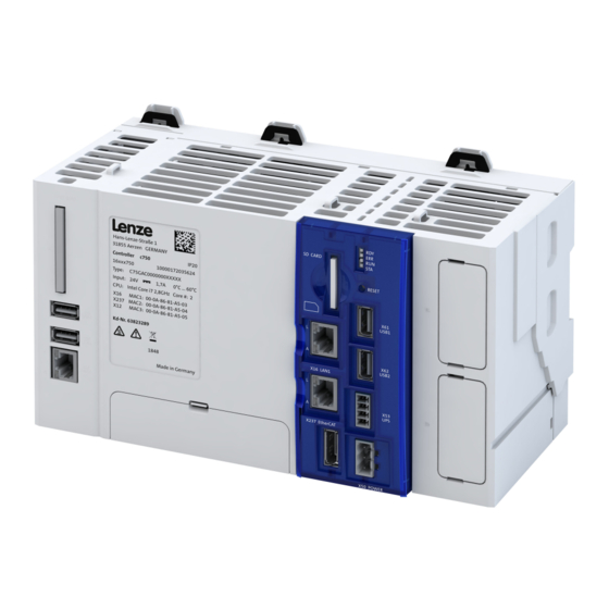
The following figure provides an overview of the elements and connections on the device. Position, size and appearance of elements and connections may vary depending on the options selected for the device. c750 controller Cable fixing (also available on base) Status LEDs... -
Page 13: Sd Card
Product information SD card SD card An already inserted SD card is included in the scope of supply of the controller. The combination of control technology software and application data on the SD card ensures that the data match the prevailing application in the present version. The SD card serves to easily exchange data in a different device. -
Page 14: Backplane Bus
Maximum resolution: 1920 x 1080 Licence information Lenze Software may contain software elements that are licensed as free software or open source. The licensing terms and conditions of the open source software components used in this product can be found in the "License"... -
Page 15: Mechanical Installation
Mechanical installation Mounting the controller Mechanical installation Mounting the controller Mounting and dismounting the controller... -
Page 16: Commissioning
• Standard network cable • Installation of »PLC Designer« For the installation, download the »PLC Designer« from the download area on the Lenze homepage to your PC and run the setup file. www.Lenze.com à Downloads Commissioning Recommended sequence of the commissioning steps... -
Page 17: Connect Controller And Engineering Pc
Commissioning Connect controller and Engineering PC Connect controller and Engineering PC A communication link from the engineering PC to the controller is required to commission the controller with the »PLC Designer«. This communication link must be wired. NOTICE Unstable LAN connection due to the use of incorrect cable types. The LAN connection may be interrupted. -
Page 18: Start Controller
Commissioning Start controller Start controller Preconditions SD card is inserted. • Controller is supplied with voltage via the terminal X50. • If I/O system 1000 modules are used, these must be installed on the backplane bus before • the start-up. The controller requires approx. -
Page 19: Access To Sd Card
The SD card's write protection must not be active for use in the controller. If write protection is activated, the PLC application will not start. Retain, boot project and logbook information will not be saved. Only use SD cards provided by Lenze. Only these SD cards have the corresponding licensing. -
Page 20: Create Plc Program
Commissioning Create PLC program Create PLC program How to create a PLC program in the target system: Preconditions »PLC Designer« has been started. 4Start controller • ^ 18 A new project has been created or a FAST Application Template is open. •... -
Page 21: Create Task
Commissioning Create task Create task How to create a task: Preconditions The PLC program has been created in the target system. 4Create PLC program • ^ 20 1. Select the Add Object/Task command from the Task Configuration context menu. A task is created. 2. -
Page 22: Log In To The Controller (Load Configuration)
Commissioning Log in to the controller (load configuration) 5.11 Log in to the controller (load configuration) How to use the »PLC-Designer« to log into the controller: Preconditions A connection between the controller and the »PLC-Designer« has been established. • 1. Use the Online Login menu command or <Alt>+<F8> to log into the controller. Logging in serves to load the device parameterization and the PLC program into the controller. -
Page 23: Parameterize Controller
Commissioning Parameterize controller General information on parameter setting 5.12 Parameterize controller 5.12.1 General information on parameter setting The controller can be parameterized in individual functions. The basic structure of the parameters is described in the following. The parameter list of the device is only available after the PLC program has been compiled. -
Page 24: Saving The Parameter Settings
Commissioning Parameterize controller Saving the parameter settings 5.12.2 Saving the parameter settings Use the "Save user data" device command to save the parameter settings of the controller locally on the SD card of the device. The parameters are part of the boot application. When creating the boot application, the parameter settings are saved automatically on the SD card of the device. -
Page 25: Start Plc Program
Commissioning Start PLC program Reset parameters to default Address Name / setting range / [default setting] Information 0x2022:039 Device commands: Load TA default settings • All parameter changes made by the user are lost during this process! • When the device command has been executed successfully, the value 0 is shown. -
Page 26: Device Settings
Device settings Device name Device settings Device name Device identification is provided by the device name of the controller. If the preset name of the controller is modified in the »PLC-Designer« project tree, this name will also be used in the Device name parameter. -
Page 27: Engineering Port
Device settings Engineering port Engineering port Parameter Address Name / setting range / [default setting] Information 0x2450 Engineering port control Activation of the engineering port settings (Ethernet). 0 No action/No error 1 Restart with current values 10 Busy 11 Action cancelled 12 Faulted 0x2451:001 Engineering port settings: IP address... -
Page 28: Time
Device settings Time Time The controller has two times of day: system time and local time. Both times are interlinked via the set time zone. System time The system time of the device is the time base for all the time-dependent actions of the controller. -
Page 29: Ntp Server Addresses
Device settings Time NTP server addresses Address Name / setting range / [default setting] Information 145 UTC+2 (OEZ) Cairo 161 UTC+0 (GMT) London 177 UTC-2 (GST) King Edward Point 187 UTC+7 (WIB) Jakarta 194 UTC+5:30 (IST) New Delhi 203 UTC+9 (JST) Tokyo 209 UTC+14 (LINT) Kiritimati 243 UTC+6:30 (MMT) Rangoon 278 UTC+5:45 (NPT) Kathmandu... -
Page 30: Device Commands
Device settings Device commands Device commands The response of the controller unit can be controlled using device commands that are defined in the parameter objects. Device commands for the logbook The controller has a logbook. The events that occur in the controller are saved in the logbook. 4Logbook ^ 97 The following device commands are available to the logbook:... -
Page 31: Save Parameter Settings
Device settings Device commands Save parameter settings 6.6.1 Save parameter settings Parameter Address Name / setting range / [default setting] Information 0x2022:003 Device commands: Save user data • When the device command has been executed successfully, the value 0 is shown. •... -
Page 32: Restart Device
The value is entered in the following parameters. 40x2013:002 Insufficient application credit results in the application being executed with a delay. Please contact your Lenze service center if you require additional application credit. The PLC application is controlled using the following device commands:... -
Page 33: Load Boot Project
Device settings Device commands Load boot project 6.6.5 Load boot project The reloaded application must be started via the following parameters: 40x2022:044 This stops a running application! Parameter Address Name / setting range / [default setting] Information 0x2022:046 Device commands: Reload boot project •... -
Page 34: Delete Log Files
Device settings Device commands Delete log files 6.6.8 Delete log files Parameter Address Name / setting range / [default setting] Information 0x2022:037 Device commands: Delete Logfiles • When the device command has been executed successfully, the value 0 is shown. •... -
Page 35: Configure Engineering Port
Configure engineering port Configure engineering port This chapter provides information on how to configure the controller during initial commissioning. The IP address settings are preserved after a system restart. If there is an active connection, changing and activating the IP setting will abort the communication with the controller. -
Page 36: Configuration Via File
Configure engineering port Configuration via file Configuration via file A file named "ip.txt" can be used to set the IP address directly. This file must be stored on the SD card in the root directory. The file can be created and copied on a Windows PC. The network settings are evaluated and accepted when the controller is booting. -
Page 37: Configuring The Network
Configuring the network Configuring the network This chapter contains information on configuring the network: 4EtherCAT ^ 38 4PROFINET ^ 71... -
Page 38: Ethercat
Configuring the network EtherCAT EtherCAT This chapter contains information on the following chapters: 4EtherCAT state machine ^ 39 4Addressing of the slaves ^ 41 4Commissioning ^ 42 4Determine the physical EtherCAT configuration (network scan) ^ 43 4Edit EtherCAT I/O mapping ^ 46 4Restart network ^ 47... -
Page 39: Ethercat State Machine
Configuring the network EtherCAT EtherCAT state machine 8.1.1 EtherCAT state machine Before communication via EtherCAT is possible, the fieldbus scans the EtherCAT state machine when booting. The following illustration shows the possible state change from the point of view of an EtherCAT slave: Init Pre-Operational Bootstrap... - Page 40 Configuring the network EtherCAT EtherCAT state machine AL status code Possible errors during transitions between states are entered in the EtherCAT register of the concerned slave in AL Status Code (address 0x0134:0x0135). Often indicated AL status code [hex] Description 0x0000 No error 0x0011 Invalid status change requested...
-
Page 41: Addressing Of The Slaves
Configuring the network EtherCAT Addressing of the slaves 8.1.2 Addressing of the slaves The EtherCAT system uses two types of addressing for the slaves: 1. Auto-increment addressing 2. Fixed-address addressing Synchronizing the internal EtherCAT slave The controller contains an internal EtherCAT slave with its own address to provide the synchronization. -
Page 42: Commissioning
Configuring the network EtherCAT Commissioning 8.1.3 Commissioning The EtherCAT master enables the control of the subordinate EtherCAT device. Connected EtherCAT slaves can be configured in this way using the engineering PC. Preconditions The field devices are installed as per the information in the device-specific mounting •... -
Page 43: Determine The Physical Ethercat Configuration (Network Scan)
Configuring the network EtherCAT Determine the physical EtherCAT configuration (network scan) 8.1.4 Determine the physical EtherCAT configuration (network scan) In order to check the physical EtherCAT configuration, you can use the »PLC Designer« to carry out a network scan on the controller online. How to carry out a network scan: 1. - Page 44 Configuring the network EtherCAT Determine the physical EtherCAT configuration (network scan) How to determine the physical EtherCAT configuration: Precondition Configuring the communication parameters • Log in to the controller • 1. Select the Start Search command in the context menu of the EtherCAT master. A dialog opens.
- Page 45 Configuring the network EtherCAT Determine the physical EtherCAT configuration (network scan) 4. Adapting the configuration: a) Click the Copy all button to copy all devices into the project. b) Copy individual devices into the project. The devices are added to the project. If a device is not available on the EtherCAT, an error message indicates this.
-
Page 46: Edit Ethercat I/O Mapping
Configuring the network EtherCAT Edit EtherCAT I/O mapping 8.1.5 Edit EtherCAT I/O mapping If you insert additional field devices in the control configuration or change the PDO mapping, the object addresses change. Therefore, the input and output objects in the PLC program must be accessed via individual unambiguous variables. -
Page 47: Restart Network
Configuring the network EtherCAT Restart network 8.1.6 Restart network The EtherCAT master communication is restarted automatically if a new configuration is loaded on the controller. These are the options for restarting the communication: 1. Request restart of the EtherCAT master. 1. -
Page 48: Diagnostics
Configuring the network EtherCAT Diagnostics 8.1.8 Diagnostics 8.1.8.1 EtherCAT master diagnostics Information is only displayed in the parameter list under Diagnostic Master if an online connection to the master has been established. The following information is displayed: Most recent error •... - Page 49 Configuring the network EtherCAT Diagnostics Address Name / setting range / [default setting] Information 0x5851:005 EtherCAT master diagnosis: Configured cycle time • Read only: x us 0x5851:006 EtherCAT master diagnosis: Connected slaves Display of the number of slaves available in the network. •...
- Page 50 Configuring the network EtherCAT Diagnostics Address Name / setting range / [default setting] Information 0x585C:011 EtherCAT master slave information: Master AL Status • Read only Bit 0 Init Bit 1 Pre-Operational Bit 2 Safe-Operational Bit 3 Operational Bit 4 Error Ind 0x585C:012 EtherCAT master slave information: Master RX Error Counter (Port 0-3)
- Page 51 Configuring the network EtherCAT Diagnostics Address Name / setting range / [default setting] Information 0x585D:010 EtherCAT master slave information: Master data link status • Read only Bit 0 EEPROM loaded correctly and PDI operational Bit 1 PDI watchdog status (reloaded) Bit 2 Enhanced link detection Bit 4 Physical link on port 0 Bit 5 Physical link on port 1...
- Page 52 Configuring the network EtherCAT Diagnostics Address Name / setting range / [default setting] Information 0x585E:005 EtherCAT master slave information: Master Serial number • Read only 0x585E:006 EtherCAT master slave information: Master Auto- increment address • Read only 0x585E:007 EtherCAT master slave information: Master Fixed address •...
- Page 53 Configuring the network EtherCAT Diagnostics Address Name / setting range / [default setting] Information 0x585F:001 EtherCAT master slave information: Master - Slave Specification of the slave address to be diagnosed. Address (AutoInc or Fixed) The first slave is an internal slave; therefore, the first external slave must -2147483648 ...
- Page 54 Configuring the network EtherCAT Diagnostics Address Name / setting range / [default setting] Information 0x585F:015 EtherCAT master slave information: Master PDI Error Counter • Read only 0x585F:016 EtherCAT master slave information: Master Lost Link Counter (Port 0-3) • Read only 0x585F:017 EtherCAT master slave information: Master DC Sync 0 Period...
-
Page 55: Error Scenarios
Configuring the network EtherCAT Error scenarios 8.1.9 Error scenarios The most common errors, faults and possibilities to correct errors can be found in the chapter 4Diagnostics and fault elimination ^ 96 In the following sections, the causes and remedies for the most frequent application errors in EtherCAT applications are described. -
Page 56: Operational" Ethercat State Is Not Achieved
Configuring the network EtherCAT Error scenarios 8.1.9.2 "Operational" EtherCAT state is not achieved The EtherCAT bus can only reach the Operational state if the fieldbus has already been set to the Pre-Operational state. If the master is set to the RUN mode, the EtherCAT bus will be set to the Operational state. 8.1.9.3 A slave does not accept a cyclic frame In the Operational state, the process data is exchanged cyclically. -
Page 57: The Network Cable Is Not Connected
The network cable is not connected. Cause The bus cable between the Lenze Controller and the first node has been unplugged. If a previously removed bus cable has been plugged back into the first EtherCAT device, the message EtherCAT_Master: EtherCAT cable connected is entered in the logbook of the controller. -
Page 58: The Drive Shafts Do Not Rotate
(In-Sync) and the DC deviation is under the preset limit value again. Currently, the Lenze controller is not re-synchronized to the distributed clocks, such that the sync pulses of the master and the ones of the slaves are different. - Page 59 Configuring the network EtherCAT Advanced configuration Address Name / setting range / [default setting] Information 0x1018:004 Identity object: Serial number Serial number: Currently not supported • Read only...
-
Page 60: Synchronisation With "Distributed Clocks" (Dc)
Within one bus cycle, the setpoints are accepted and the actual values are detected in the field devices at always exactly the same time. If the Lenze controller (master) is synchronous with the distributed clocks, the actual values acquired by the slave are sent to the master at the end of the bus cycle and setpoints from the master are sent to the slaves for processing. - Page 61 Not all slaves support the DC functionality. When additional slaves are added, devices with and without DC capability can be mixed. The first EtherCAT slave after the Lenze controller must be the DC master that supplies the other EtherCAT devices and the controller with the...
-
Page 62: Set Dc Synchronization
Not all slaves support the DC functionality. When additional slaves are added, devices with and without DC capability can be mixed. The first EtherCAT slave after the Lenze controller must be the DC master that supplies the other EtherCAT devices and the controller with the exact time. - Page 63 2. Open the EtherCAT I/O image tab and select the bus cycle task for the master. The Cycle settings of the higher-level bus serve to use the bus cycle task set via the PLC settings tab of the Lenze controller (device):...
- Page 64 Configuring the network EtherCAT Advanced configuration 3. Select the DC functionality DC for synchronization in the device tree for the first slave (DC master) under the master. If a slave does not support any distributed clocks, only DC unused can be selected here.
-
Page 65: Modular Machine Configuration
Configuring the network EtherCAT Modular machine configuration 8.1.11 Modular machine configuration The modular machine configuration can be used from release 3.10 onwards! The modular machine configuration enables only one project to be used for all machine variants (maximum configuration). 8.1.11.1 Behavior of the EtherCAT master When the modular machine configuration is used, the EtherCAT master behavior differs from the behavior known so far:... -
Page 66: Mandatory Slaves/Optional Slaves
Configurations serve to indicate whether an EtherCAT slave is mandatory or optional. The configurations are summarized in the "mmc-0-conf.csv" text file on the Lenze controller. More identifying features of the slaves are included in the text file "mmc-0-ident.csv". -
Page 67: Configuration Files
Moreover, the modular machine configuration makes it possible to use CoE objects for further identification of the EtherCAT slaves. These additional identification features are contained in the "mmc-0-ident.csv" text file. If the identification file is not available on the Lenze controller, no identification features are used. -
Page 68: Address Assignment
Configuring the network EtherCAT Modular machine configuration configuration is based on the designator (STRING). If a slave has to be contained in a configuration (Mandatory Slave), it is marked by an 'X' in the following sample table. Address 1001 1002 1003 Inverter i700... -
Page 69: Error Messages
MMC - Internal error (...) ERROR An internal error has occurred. The internal error number is output in the error message. Please contact Lenze customer service! MMC - invalid alias address ... at ERROR While the EtherCAT bus was booted and the slaves were checked, a slave with an position ... - Page 70 Configuring the network EtherCAT Modular machine configuration Error message Error type Description MMC - slave ... ident failed - CoE ... ERROR An error occurred in the specified slave while the EtherCAT bus booted and the (error ...) additional identification parameters from the "mmc-0-ident.csv" configuration file were checked.
-
Page 71: Profinet
Configuring the network PROFINET PROFINET This chapter contains information on the following chapters: 4Commissioning ^ 73 4Basic setting and options ^ 75 4Process data transfer ^ 76 4Parameter data transfer ^ 77 4Monitoring ^ 78 4Diagnostics ^ 79 PROFINET® (Process Field Network) is a real-time capable network based on Ethernet. PROFINET®... - Page 72 Configuring the network PROFINET Fig. 5: PROFINET connections X2x6 and X2x7 Typical topologies Line Tree Ring IO controller Switch SCALANCE (MRP capable) IO device Redundant domain...
-
Page 73: Commissioning
1. Importing IO devices into the control configuration: 1. Select the "Add device" command in the context menu of the target system (device, Lenze controller, ...) to extend the control configuration with the IO device. 2. Name the inserted IO device sensibly. -
Page 74: Settings In The Siemens "Tia Portal
Here, commissioning with the Siemens »TIA Portal« is described. Please note that in the default setting of the Siemens, »TIA Portal« changes to network parameters carried out previously by a Lenze engineering tool (e. g. »EASY Starter«) may be overwritten. -
Page 75: Basic Setting And Options
Configuring the network PROFINET Basic setting and options 8.2.2 Basic setting and options 8.2.2.1 Station name and IP configuration The station name and the IP configuration can be assigned by the IO-Controller. These settings enable the IO-Controllerto identify the devices in the network and manage the data exchange. The station name and the IP configuration can also be assigned by the »Engineering Tool«. -
Page 76: Suppress Diagnostic Messages To The Io Controller
Configuring the network PROFINET Process data transfer 8.2.2.2 Suppress diagnostic messages to the IO controller serves to set which error response in the device suppresses the alarm message 40x285A:001 to the IO-Controller. Parameter Address Name / setting range / [default setting] Information 0x285A:001 Diagnostic configuration: Alarm supression... -
Page 77: Parameter Data Transfer
Configuring the network PROFINET Parameter data transfer 8.2.4 Parameter data transfer Data communication with PROFINET is characterised by the simultaneous operation of cyclic and acyclic services in the network. As an optional extension, the parameter data transfer belongs to the acyclic services, which provides access to all device parameters. The access to the device data depends on the PROFIdrive profile. -
Page 78: Monitoring
Configuring the network PROFINET Monitoring Assignment of the user data depending on the data type Depending on the data type used, the user data is assigned as follows: Data type Length User data assignment Byte 1 Byte 2 Byte 3 Byte 4 Byte ... -
Page 79: Diagnostics
Configuring the network PROFINET Diagnostics 8.2.6 Diagnostics 8.2.6.1 LED status display Notes on the connection status with IO-Controller can be obtained via the LEDs "BUS RDY" and "BUS ERR" of the PROFINET option (front of the device). In addition, the LEDs "Link" and "Activity" at the RJ45 sockets indicate the connection status to the network. - Page 80 Configuring the network PROFINET Diagnostics Address Name / setting range / [default setting] Information 0x2388 PROFINET status Bit coded display of the current Bus status. • Read only Bit 0 Initialized Bit 1 Online Bit 2 Connected Bit 3 IP address error The IP address is invalid.
-
Page 81: Device Functions
Device functions Device identification Device functions Device identification The controller consists of various partial components. The current versions are visible in a set of parameters. Parameter Address Name / setting range / [default setting] Information 0x2000:001 Device data: Product code Product code of the controller •... -
Page 82: Switch-Off Behavior
Device functions Switch-off behavior Retain variables and persistent variables Switch-off behavior The controller has internal buffer capacitors to save data during the shutdown process. This memory function is initiated automatically if a voltage failure is detected. Certain circuit sections, e.g. backplane bus supply and USB, are switched off directly in the event of voltage failure in order to maintain voltage for the internal saving process for a constant amount of time. -
Page 83: Reset Controller
Device functions Reset controller Reset controller To reset the device, press the reset button. 4Features ^ 12 How to carry out a restart: 1. Keep the reset key pressed for approx. 1 s. The LEDs are off. After the restart, the LED "RUN" is green. How to carry out a hardware reset: 1. -
Page 84: Open System Functionality
Open system functionality Open system functionality The open system architecture used in the device divides the computing power on two independent operating systems. The Real-Time-Linux is responsible for control tasks. The preinstalled Windows 10 IoT Enterprise can be used for user-specific software applications und thus enables an easy connection to an IT infrastructure. -
Page 85: Preinstalled Windows 10 Iot Enterprise
Open system functionality Preinstalled Windows 10 IoT Enterprise 10.1 Preinstalled Windows 10 IoT Enterprise The CFast card comes with a preinstalled Microsoft Windows 10 IoT Enterprise operating system. Before commissioning, a backup copy of the CFast card should be made. 4Back up and restore the Windows installation image ^ 86 Licensing terms... -
Page 86: Back Up And Restore The Windows Installation Image
Open system functionality Preinstalled Windows 10 IoT Enterprise Back up and restore the Windows installation image 10.1.1 Back up and restore the Windows installation image The delivery status of the CFast card with preinstalled Windows 10 IoT can be secured with the Microsoft tool "DISM"... -
Page 87: Protect Windows From Unwanted Changes
Open system functionality Preinstalled Windows 10 IoT Enterprise Protect Windows from unwanted changes 10.1.2 Protect Windows from unwanted changes Microsoft provides various tools ("Lockdown features") to set Windows 10 IoT for special purposes: Unified Write Filter • Keyboard Filter • Shell Launcher •... -
Page 88: Back Up And Restore The Windows System Image
Open system functionality Set up remote desktop connection to the open system Back up and restore the Windows system image 10.1.4 Back up and restore the Windows system image An already configured Windows 10 IoT including created users and additionally installed programs can be saved as an image to be used for further controllers. -
Page 89: Install Ups Driver
10.3 Install UPS driver For using the c750 controller with Windows 10 IoT, you have to provide for an external uninterruptible power system (UPS) which, in case the 24 V supply fails, provides enough time to be ended in an orderly manner. -
Page 90: Virtual Network Interface
The »PLC Designer« engineering tool can be directly installed in the open system (Windows 10 IoT) of the controller. The 'localhost' gateway address must be entered in the connection settings for the device. • After "Search network", the c750 controller responds with device identification, IP and • MAC address. See also: 4Establish connection between controller and »PLC Designer«... -
Page 91: Device Commands For Operating System Control
Open system functionality Device commands for operating system control 10.6 Device commands for operating system control The control section provides device commands which directly influence Windows 10 IoT. The current status of Windows 10 IoT can also be detected and used in the PLC program. Device commands for controlling Windows 10 IoT Windows can be directly influenced via the device commands. - Page 92 Open system functionality Device commands for operating system control Address Name / setting range / [default setting] Information 0x2051:001 GPOS diagnostics: OS State • Read only 0 Unknown The status for Windows 10 IoT cannot currently be determined. 1 Halted The Windows 10 IoT is in "Hold"...
-
Page 93: Replace Controller
Replace controller Dismount controller Replace controller A defective controller can only be replaced by a device of the same product type. The replacement device must have the same features, such as optionally integrated communication cards and connections. 11.1 Dismount controller More information For certain tasks, more information is available in additional documents. -
Page 94: Install New Controller
Replace controller Install new controller 11.2 Install new controller The current firmware version of the controller is also stored on the SD card used. If the SD card is inserted into a new device, the firmware version from the SD card is imported into the device automatically. -
Page 95: Upgrade/Downgrade Of The Controller
USB flash drive with at least 200 MB free memory • The firmware package to be installed via the »Package-Manager« is selected via the Lenze »Firmware loader«. The selected firmware is then copied to the USB flash drive inserted in the engineering PC. How to install the firmware: 1. -
Page 96: Diagnostics And Fault Elimination
Diagnostics and fault elimination LED status display Diagnostics and fault elimination This section contains information on error handling, drive diagnostics and fault analysis. 13.1 LED status display The controllers are equipped with LEDs indicating the current operating status. Depending on the running software application, different control modes of the LEDs are possible. -
Page 97: Logbook
Diagnostics and fault elimination Logbook 13.2 Logbook The devices are equipped with a logbook function which records system events and error messages. The entries in the logbook make it easier to diagnose the automation system. The following information is processed by the logbook: Error messages and events of the application are displayed. -
Page 98: Diagnostic Parameters
Diagnostics and fault elimination Diagnostic parameters PLC diagnostics 13.3 Diagnostic parameters 13.3.1 PLC diagnostics The following information may be retrieved for diagnostic purposes: Information on the event currently active in the controller (event monitor) • Status of the SD card •... -
Page 99: Network Diagnostics
Diagnostics and fault elimination Diagnostic parameters Network diagnostics Address Name / setting range / [default setting] Information 0x2012:005 Device information: SD card free memory Display of the currently free memory on the SD card in kilobytes. • Read only 0x2012:006 Device information: SD card used memory Display of the currently occupied memory on the SD card in kilobytes. -
Page 100: Service Life Diagnostics
Diagnostics and fault elimination Error handling Service life diagnostics Address Name / setting range / [default setting] Information 0x231F:002 Communication module ID: Module ID connected Display of the network options currently available in the device. • Read only Note! When switched on, the device checks whether the parameter settings saved in the memory module match the device hardware and firmware. -
Page 101: Appendix
Appendix Parameter attribute list Appendix 14.1 Parameter attribute list The parameter attribute list contains all parameters of the controller. • The parameter attribute list is sorted by addresses (index:subindex) in ascending order. • How to read the parameter attribute list: Column Meaning Address... - Page 102 Appendix Parameter attribute list Address Name Default setting Data type 0x2014:001 General network identification: Hostname - (Read only) STRING[128] 0x2015:001 CPU usage: Core A x % (Read only) 0x2015:002 CPU usage: Core B x % (Read only) 0x2022:001 Device commands: Load default settings Off / ready [0] 0x2022:003 Device commands: Save user data...
- Page 103 Appendix Parameter attribute list Address Name Default setting Data type 0x245B:002 System time: Current time 0x245C:001 Local time: Current timezone UTC+1 (MEZ) Brussels [52] 0x245C:002 Local time: Current time 0x2462:001 Active virtual port settings: IP address - (Read only) 0x2462:002 Active virtual port settings: Subnet - (Read only) 0x2462:003...
- Page 104 Appendix Parameter attribute list Address Name Default setting Data type 0x585C:017 EtherCAT master slave information: Master DC Sync 0 Period x ns (Read only) 0x585C:018 EtherCAT master slave information: Master DC Sync 1 Period x ns (Read only) 0x585D:001 EtherCAT master slave information: Master - Slave Address (AutoInc or Fixed) 0x585D:002 EtherCAT master slave information: Master VendorID...
- Page 105 Appendix Parameter attribute list Address Name Default setting Data type 0x585F:014 EtherCAT master slave information: Master Processing Unit Error - (Read only) Counter 0x585F:015 EtherCAT master slave information: Master PDI Error Counter - (Read only) 0x585F:016 EtherCAT master slave information: Master Lost Link Counter (Port 0-3) - (Read only) 0x585F:017 EtherCAT master slave information: Master DC Sync 0 Period x ns (Read only)
- Page 106 © 12/2019 | | 1.0 Lenze Automation GmbH Postfach 101352, 31763 Hameln Hans-Lenze-Str. 1, 31855 Aerzen GERMANY HR Hannover B 205381 Phone +49 5154 82-0 Fax +49 5154 82-2800 sales.de@lenze.com www.Lenze.com Lenze Service GmbH Breslauer Straße 3, 32699 Extertal GERMANY...
Need help?
Do you have a question about the C750 and is the answer not in the manual?
Questions and answers