
Related Manuals for RadioLink Turbo PIX


Summary of Contents for RadioLink Turbo PIX
- Page 1 Radiolink Electronic Ltd www.radiolink.com TURBO PIX User Manual Compatible with Fixed-wing/Glider/Multirotor/Helicopter/Car/Boat/Robot CE FCC RoHS...
- Page 2 Radiolink Electronic Ltd www.radiolink.com Thank you for purchasing RadioLink flight controller Turbo Pix. To fully enjoy the benefits of this product and ensure safety, please read the manual carefully and set up the device as instructed steps. If any problems found during the operation process, either way listed below can be used as online tech support.
- Page 3 1 Piece FC Status Indicator Connect 1 Piece Board(Motor output, connect Cable ESC/motor) This manual is based on the ARDUPILOT, with setting with RadioLink transmitter AT9S as example. More details about how to use flight controller PIXHAWK-series please refer to: http://ardupilot.org/copter/docs/initial-setup.html...
-
Page 4: Table Of Contents
F/S(failsafe) Setting................................30 Radio Failsafe Setup ..............................30 EKF FailSafe .................................34 Optional hardware setup ..............................35 Install Turbo Pix on aircraft ............................35 Connect Turbo Pix to the aircraft..........................36 5.2.1 Motor order rotation select ..........................36 5.2.2 How to recognizing clockwise and counterclockwise propellers ........ -
Page 5: Turbo Pix Introduction
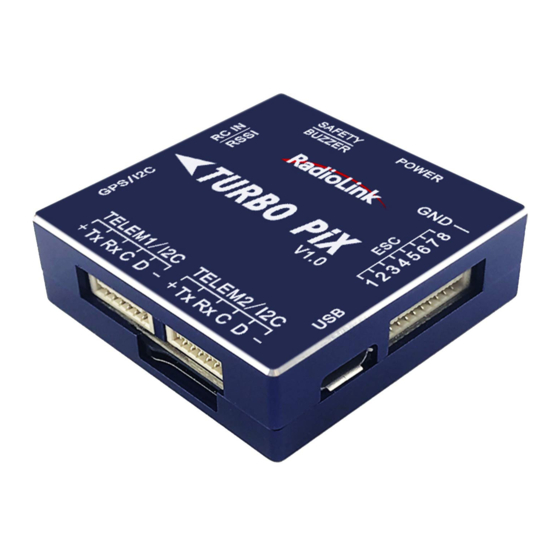
With the dimension of 39*39*12mm and the weight of 27g including cables, Turbo Pix lightens the whole weight of the aircraft and diminishes battery consumption, allowing longer flight time. The 8- channel output fits all models including fixed-wing/helicopter/car/boat/3-8 copters. -
Page 6: Advices
1.2 Advices For the users who firstly use Turbo Pix, we suggest that you use Turbo Pix following below steps: 1. You have to install the mission planner and driver from here and familiar with the menu. Download the latest Mission Planner from here: http://www.radiolink.com.cn/firmware/MissionPlanner/MissionPlanner-latest.exe... -
Page 7: Mission Planner
Radiolink Electronic Ltd www.radiolink.com 2. To establish a connection you must first choose the communication method/channel you want to use, and then set up the physical hardware and Windows device drivers. You can connect the PC and autopilot using USB cables, Telemetry Radios, Bluetooth, IP connections etc. -
Page 8: Mission Planner Introduction
INTIAL SETUP: for firmware installation and update, Mandatory Hardware and Optional Hardware setup CONFIG/TUNING: including detailed PID setup and parameters change SIMULATION: make Turbo Pix work as a simulator after upgrade a special simulation firmware HELP: you can get help when you have questions about MP... -
Page 9: Initial Setup
3. Initial Setup First, you have to upgrade the firmware you need when you the first time ready to use Turbo Pix. Radiolink Turbo Pix is default with quadcopter firmware, you have to install the right firmware if you use the other frame drone. - Page 10 After upgrade firmware 3.1 or after version 3.1,there will be a pop-up warning motors will run at idle speed after disarmed. Please click “CONNECT” to connect your Turbo Pix and computer when firmware has installed successful. it turns to green means connect successful.
- Page 11 Radiolink Electronic Ltd www.radiolink.com Pay attention: Please set Layout from “Basic” to “Advanced” in CONFIG/TUNING menu if any of the three questions as below encontered when you installing the Mission Planner. (1) It takes a long time to read the parameters.
-
Page 12: Frame Type
3.2 Frame Type Please setup as below: 1. INITIAL SETUP 2. Mandatory Hardware->Frame Type 3. Choose Quad or Hexa or other frame types as you need 3.3 Accelerometer Calibration Make sure the Turbo Pix is keeping horizontal when do the accel calibration. - Page 13 2. Place vehicle on its LEFT side and press any key to save setting. Direction points to left Keep Turbo Pix perpendicular to the horizontal plane 3. Place vehicle on its RIGHT side and press any key to save setting.
-
Page 14: Compass Calibration
If the GPS mounted with the same direction with flight controller, then it need not to setup the direction of GPS in MP but if you mounted the GPS with the different direction of Turbo Pix, you have to setup in the MP. - Page 15 Keep the same direction with flight controller. positioning. Please fixed Turbo Pix and TS100, then click “Start” and turn Turbo Pix and TS100 till the progress bar of Mag 1 and 2 to the end and comes out the MAG_CAL_SUCCESS marked words.
- Page 16 Radiolink Electronic Ltd www.radiolink.com The mission planner will keep recording the data that collected by the compass sensor and the progress bar and the percentage will keep change when you calibrate the compass, if the percentage have not changed, please check if the compass is connect success.
- Page 17 The mission planner will remind you when the compass has calibrated success. Click OK and then reconnect Turbo Pix to computer, compass calibrate success after restart the Turbo Pix. Attention: When the progress bar moves to 100 and then restart from 0, it may because of the wrong calibrate action or interference.
-
Page 18: By Transmitter
4. Power on the transmitter, the throttle gimbal stick should be at the lowest position. 5. Power on Turbo Pix annd wait until its self-check is complete. The normal notification should be RED indicator flashes quickly-- buzzer makes DEE sounds -- Red and Green indicators flash quickly-- Red/Green/Blue indicators flash intervally-Red and Green indicators flash quickly, then self-check is done. -
Page 19: Radio Calibration
Radiolink Electronic Ltd www.radiolink.com 8. When there are three D sounds made by the buzzer, it means the compass calibration is done with success. Restart the flight controller and it’s enabled. Note 1. If calibration fails, there would be two D sounds from the buzzer then continuous DD sounds like once per second, meaning the flight controller restarts to calibrate. - Page 20 Bind your transmitter and receiver before calibrate radio, connect Turbo Pix to computer via USB cable and then turn on transmitter. The RC receiver ask to connect to the RC port of Turbo Pix. The transmitter will make AT9S as an example in this manual.
- Page 21 Radiolink Electronic Ltd www.radiolink.com 5. Click “Calibrate Radio” There are two tool pop-ups after you click “OK”, one for make sure both your transmitter and receiver are powered on and connected, and the motor of your drone does not have power and without propellers.
- Page 22 Radiolink Electronic Ltd www.radiolink.com If the red bars have not any change when you move the sticks, please check the receiver have connect success or not, make sure the receiver (maybe R9DS) is output SBUS signal (the blue LED of R9DS means work as SBUS signal).
-
Page 23: Flight Modes
3.6 Flight Modes Turbo Pix has 20 flight built-in flight modes, 10 of which are regularly used. There are modes to support different levels/types of flight stabilization, a sophisticated autopilot, a follow-me system etc. Flight modes are controlled through the radio (via a transmitter switch), via mission commands, or using commands from a ground station (GCS) or companion computer. - Page 24 Radiolink Electronic Ltd www.radiolink.com 2. Press Mode button twice to into ADVANCE MENU, press Push button into ATTITUDE setting menu, CH5 is default to the attitude control channel and please choose a 3 Posi-SW and a 2 Posi-SW to control the attitude.
-
Page 25: Stabilize Mode
Radiolink Electronic Ltd www.radiolink.com 3.6.1 Stabilize Mode Stabilize mode allows you to fly your vehicle manually, but self-levels the roll and pitch axis. If you’re learning to fly, try Alt Hold or Loiter instead of Stabilize. You’ll have fewer crashes if you don’t need to concentrate on too many controls at once. -
Page 26: Altitude Hold Mode
Radiolink Electronic Ltd www.radiolink.com Parameters Setting ACRO_RP_P controls the rotation rate for the roll and pitch axis. The default, 4.5, will command a 200deg/sec rotation rate. Higher values lead to higher rotation rates, lower to slower rotation rates. ACRO_YAW_P controls the rotation rate for the yaw axis. The default, 4.5, like roll and pitch, will command a 200deg/sec rotation rate. -
Page 27: Auto Mode
Radiolink Electronic Ltd www.radiolink.com Note: The flight controller uses a barometer which measures air pressure as the primary means for determining altitude (“Pressure Altitude”) and if the air pressure is changing in your flight area due to extreme weather, the copter will follow the air pressure change rather than actual altitude. When fitted and enabled, a downward facing rangefinder such as LiDAR or SONAR will automatically provide even more accurate altitude maintenance, up to the limit of the sensor. - Page 28 AUTO should be set-up as one of the Flight Modes on the flight mode switch. Make sure that the GPS is positioning first: The LED of Turbo Pix is green. The LED of GPS and compass module is blinking.
-
Page 29: Poshold Mode
Radiolink Electronic Ltd www.radiolink.com camera on it) as the copter flies the mission. The autopilot will attempt to retake yaw control as the vehicle passes the next waypoint. Ending a mission Missions should normally have an RTL as their final command to ensure the copter will return after the mission completes. - Page 30 Radiolink Electronic Ltd www.radiolink.com RTL is a GPS-dependent move, so it is essential that GPS lock is acquired before attempting to use this mode. Before arming, ensure that the APM’s blue LED is solid and not blinking. For a GPS without compass, the LED will be solid blue when GPS lock is acquired.
-
Page 31: Simple And Super Simple Modes
Radiolink Electronic Ltd www.radiolink.com (2) The final return altitude may be adjusted from 0 to 1000 centimeters. 3. RTL_LOIT_TIME: Time in milliseconds to hover/pause above the “Home” position before beginning final descent. The “Loiter” time may be adjusted from 0 to 60,000 milliseconds. - Page 32 Radiolink Electronic Ltd www.radiolink.com Normal Mode Without Simple or Super Simple enabled, the pilot’s transmitter stick inputs are applied in the orientation of the copter. For example, in the diagram above when the pilot applies roll input right (red) the vehicle rolls to its right.
-
Page 33: More Flight Modes
Radiolink Electronic Ltd www.radiolink.com Generally, when arming you should stand behind the vehicle with its nose pointing directly away from you. While flying you should try to keep the vehicle flying in front of its starting position because if it flies behind you all the controls will feel reversed. -
Page 34: F/S(Failsafe) Setting
4. F/S(failsafe) Setting 4.1 Radio Failsafe Setup Turbo Pix supports Return-To-Launch in cases where contact between the Pilot’s RC transmitter and the flight controller’s receiver is lost. This page explains this failsafe’s setup and testing. Note the “Radio failsafe” was previously called “Throttle failsafe”... - Page 35 Receiver and flight controller Turbo Pix setup: By default, a newly purchased receiver will be set-up to simply hold all channels at their last known position when the receiver and transmitter lose contact. This is not good because the flight controller has no way to know that the Pilot has lost control of the vehicle.
- Page 36 Radiolink Electronic Ltd www.radiolink.com transmitter is off. (2) at least 10 lower than your channel 3’s PWM value when the throttle stick is fully down and the transmitter is on. (3) above 910. Click OK to into the failsafe setting menu.
- Page 37 Radiolink Electronic Ltd www.radiolink.com You can turn off transmitter to check if the Failsafe function setup success(the PWM of CH3 is smaller than 975) If enabled and set-up correctly the radio Failsafe will trigger if: (1) The pilot turns off the RC transmitter.
-
Page 38: Ekf Failsafe
Radiolink Electronic Ltd www.radiolink.com You can check your Failsafe by performing the following tests with the Turbo Pix connected to the Mission Planner either via a USB cable or telemetry link. You can complete these tests without plugging in your LiPo battery but if you do connect a battery you should first remove the propellers. -
Page 39: Optional Hardware Setup
Prepare a drone first, a X frame quadcopter as a sample, please mount a Turbo Pix as below steps after you have assembled the drone. 1. mount a Turbo Pix on the center position of the drone, and make sure that the Turbo Pix is horizontal on the drone. -
Page 40: Connect Turbo Pix To The Aircraft
Radiolink Electronic Ltd www.radiolink.com 5.2 Connect Turbo Pix to the aircraft 5.2.1 Motor order rotation select Green means CW Blue means CCW Legend for motor-order diagrams Quadcopters Hexacopter Octocopter... - Page 41 Radiolink Electronic Ltd www.radiolink.com Tricopter Note Since there’s no voltage output from the flight controller, an extra BEC module needs to be connected to power supply servo for this model frame...
-
Page 42: How To Recognizing Clockwise And Counterclockwise Propellers
Radiolink Electronic Ltd www.radiolink.com 5.2.2 How to recognizing clockwise and counterclockwise propellers The diagrams above show two types of propellers: clockwise (called pushers) and counterclockwise (called pullers). Pusher propellers are often marked with a P. However not all propellers are marked and both types are often available in either rotational direction. - Page 43 Allows the autopilot firmware to more accurately compensate for the interference on the compass from other components. The 6-pin cable plugs into the 6-pin connector on both the Power Module and Turbo Pix. Mission Planner Setup Battery measurement is primarily set up in the Mission Planner ‘s INITIAL SETUP -- Optional Hardware -- Battery Monitor screen.
- Page 44 Radiolink Electronic Ltd www.radiolink.com If you find the voltage is not correct (i.e. if off from the hand-held volt meter’s reading by more than perhaps 0.2V) you can correct the APM/PX4’s reading by doing the following: 1. On Mission Planner ‘s INITIAL SETUP | Optional Hardware | Battery Monitor screen set the “Sensor” to “Other”.
-
Page 45: Led Indicator, Arming And Troubleshooting
Radiolink Electronic Ltd www.radiolink.com Using the power analyzer you can also measure the current and compare to results displayed in the Mission Planner. 5.3 LED Indicator, Arming and Troubleshooting 5.3.1 LED Indicator Blue and red flashing: Initializing Yellow flashing twice: Error, Arming rejected Blue flashing: Stabilize, can be armed. - Page 46 6. If you are planning on using the autopilot (i.e. Loiter, RTL, Drift, Auto or Guided modes) you should wait for 30 seconds after the GPS has gotten 3d lock. This will give the GPS position time to settle. On a Turbo Pix the RGB LED will blink green.
- Page 47 Radiolink Electronic Ltd www.radiolink.com Compasses inconsistent: the internal and external compasses are pointing in different directions (off by >45 degrees). This is normally caused by the external compasses orientation (i.e. COMPASS_ORIENT parameter) being set incorrectly. GPS related failures: GPS Glitch : the GPS is glitching and the vehicle is in a flight mode that requires GPS (i.e. Loiter, PosHold, etc) and/or the circular fence is enabled.
- Page 48 If you connect the battery and armed, the motors begin to have speed even though the throttle is at zero from the version 3.1 firmware. It reminds you that Turbo Pix is in service and please take care of the safety.
-
Page 49: Esc Calibration
Assembly Instructions. Next follow these steps: Before calibrating ESCs, please ensure that your copter has NO PROPS on it and that the Turbo Pix is NOT CONNECTED to your computer via USB and the LiPo battery is disconnected. -
Page 50: Level Calibration
Radiolink Electronic Ltd www.radiolink.com 6. Wait for your ESCs to emit the musical tone, the regular number of beeps indicating your battery’s cell count (i.e. 3 for 3S, 4 for 4S) and then an additional two beeps to indicate that the maximum throttle has been captured. -
Page 51: Geofence
Radiolink Electronic Ltd www.radiolink.com 5.6 GeoFence AC 3.0.1 (and higher) includes a simple “tin can” shaped fence centered on home that will attempt to stop your copter from flying too far away by stopping at the fence (if in Loiter mode and using Copter-3.4 or higher) or initiating an RTL. - Page 52 20m out which will again switch the copter to LAND if it continues away from home. Enabling the Fence in Mission Planner The Fence can be set-up by doing the following: 1. Connect your flight controller Turbo Pix to the Mission Planner. 2. Go to the Config/Tuning -- GeoFence screen. 3. Click the Enable button.
- Page 53 Radiolink Electronic Ltd www.radiolink.com Warning 1. The minimum recommended fence radius is 30m. 2. The fence requires the GPS to be functioning well so do not disable the GPS arming check nor the EKF failsafe while the fence is enabled. Conversely if you disable either of these checks, disable the Fence.
-
Page 54: Autotune
Radiolink Electronic Ltd www.radiolink.com 6. AutoTune AutoTune attempts to automatically tune the Stabilize P, Rate P and D, and maximum rotational accelerations to provide the highest response without significant overshoot. Copter needs to be “basically” flyable in AltHold mode before attempting to use AutoTune as the feature needs to be able to “twitch” the copter in the roll and pitch axis. - Page 55 If the vehicle feels sloppy after the AutoTune, try increasing the AUTOTUNE_AGGR parameter as high as 0.10 and attempt the autotune again. All of the parameters of Turbo Pix can setup in Mission Planner, please do not change the parameters during the flight.
- Page 56 Refresh Params: exhibit the newest parameters which have modified no the Mission Planner. Compare Params: compare the current and the previous parameters. Load Presaved: load the parameters that Radiolink upgrade the files which design for 210-250 frame racing drone to Turbo Pix.
-
Page 57: Download Dataflash Log
Dataflash logs use the Turbo Pix onboard dataflash memory, which you can download after the flight. On Plane and Rover dataflash logs are created soon after start-up. On Copter they are created after you first arm the copter. - Page 58 Radiolink Electronic Ltd www.radiolink.com More details about how to use PIXHAWK, Turbo Pix, APM, please check on this website: http://ardupilot.org/copter/docs/common-mission-planning.html...
Need help?
Do you have a question about the Turbo PIX and is the answer not in the manual?
Questions and answers