RadioLink Crossflight User Manual
Multirotor
Hide thumbs
Also See for Crossflight:
- User manual (73 pages) ,
- Quick start manual (7 pages) ,
- User manual (62 pages)

Related Manuals for RadioLink Crossflight


Summary of Contents for RadioLink Crossflight
- Page 1 User Manual for Multirotor (Compatible with Fixed-wing/Glider/Multirotor/Helicopter/Car/Boat/Robot) CE FCC RoHS...
- Page 2 2. Send message to us on our Facebook page or leave comments on our YouTube page 3. If the product is purchased from the local distributor, you can also ask them for support and repair as prefer. All manuals and firmware are available on RadioLink official website www.radiolink.com and more tutorials are uploaded.
- Page 3 Changes or modifications not expressly approved by the party responsible for compliance could void the user's authority to operate the equipment. This manual is based on the ARDUPILOT, with setting with RadioLink transmitter AT9S as example. http://ardupilot.org/copter/docs/initial- More details about how to use flight controller please refer to:...
-
Page 4: Table Of Contents
4.2 EKF FailSafe ............................37 5. Optional hardware setup ..........................38 5.1 Install crossflight on aircraft ......................... 38 5.2 Connect crossflight to the aircraft ....................... 39 5.2.1 Motor order rotation select ......................39 5.2.2 How to recognizing clockwise and counterclockwise propellers ..........41 5.2.3 Connect the Spare Parts ...................... - Page 5 Radiolink Electronic Ltd www.radiolink.com 5.3.1 LED Indicator ..........................44 5.3.2 Arming and Disarming ........................44 5.4 ESC Calibration ............................. 48 5.5 Level Calibration ............................49 5.6 GeoFence ...............................50 5.7 Onboard OSD ............................53 5.7.1 Setting Introduction ........................53 5.7.2 Screen Introduction ........................54 6. AutoTune ..............................55...
-
Page 6: Crossflight Introduction
Radiolink Electronic Ltd www.radiolink.com 1. crossflight Introduction 1.1 Spare Parts... -
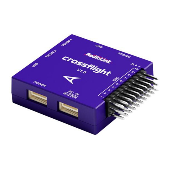
Page 7: Connectors
Radiolink Electronic Ltd www.radiolink.com 1.2 Connectors... -
Page 8: Parameters
Radiolink Electronic Ltd www.radiolink.com 1.3 Parameters 39.7*39.7*13mm Weight & Dimension Dimension (1.56"*1.56"*0.51") 16.5g (0.58oz), 54g (1.9oz when all Weight the connect wires included) Hardware Processor HC32F4A0PITB Sensor Gyro ICM42670 Compass VCM5883L Barometer LPS22HB Without FRAM, use the internal flash to store parameters, 2617... -
Page 9: Advices
-40~80℃ 1.4 Advices For the users who firstly use crossflight, we suggest that you use crossflight following below steps: 1. You have to install the mission planner and driver from here and familiar with the menu. Download the latest Mission Planner from here: https://www.radiolink.com/crossflight_missionplanner... -
Page 10: Mission Planner Introduction
Radiolink Electronic Ltd www.radiolink.com Then download the Mission Planner from https://www.radiolink.com/crossflight_missionplanner Open the Microsoft installer file and select Run to run the installation utility. 2.2 Mission Planner Introduction Once installation is complete, open Mission Planner by clicking on its system icon. -
Page 11: Initial Setup
RadioLink. The default firmware of crossflight is for Multicopter. First, you have to upgrade the firmware you need when you the first time ready to use crossflight. Radiolink crossflight is default with quadcopter firmware, you have to install the right firmware if you use the... -
Page 12: Download And Install Firmware
Click “Yes” to install the firmware, Disconnect the USB cable, click OK and then reconnect USB cable immediately (Pay attention: crossflight will have failed to connect if there are more than one COM, please remove other equipment if disconnect). Red status LED means the crossflight is loading the firmware. - Page 13 Radiolink Electronic Ltd www.radiolink.com Pay attention: Please set Layout from “Basic” to “Advanced” in CONFIG/TUNING menu if any of the three questions as below encontered when you installing the Mission Planner. (1) It takes a long time to read the parameters.
-
Page 14: Frame Type
3.2 Frame Type Please setup as below: 1. INITIAL SETUP 2. Mandatory Hardware->Frame Type 3. Choose Quad or Hexa or other frame types as you need 3.3 Accelerometer Calibration Make sure the crossflight is keeping horizontal when do the accel calibration. - Page 15 Radiolink Electronic Ltd www.radiolink.com 1. Place vehicle level and press any key to save setting. 2. Place vehicle on its LEFT side and press any key to save setting.
- Page 16 Radiolink Electronic Ltd www.radiolink.com 3. Place vehicle on its RIGHT side and press any key to save setting. 4. Place vehicle DOWN and press any key to save setting. 5. Place vehicle UP and press any key to save setting.
-
Page 17: Compass Calibration
GPS in MP but if you mounted the GPS with the different direction of crossflight, you have to setup in the MP. Compass calibrate... - Page 18 Radiolink Electronic Ltd www.radiolink.com Please fixed crossflight and TS100, then click “Start” and turn crossflight and TS100 till the progress bar of Mag 1 and 2 to the end and comes out the MAG_CAL_SUCCESS marked words. Calibrate the compass as these steps below: Hold the vehicle in the air and rotate it slowly so that each side (front, back, left, right, top and bottom) points down towards the earth for a few seconds in turn.
- Page 19 Radiolink Electronic Ltd www.radiolink.com The mission planner will keep recording the data that collected by the compass sensor and the progress bar and the percentage will keep change when you calibrate the compass, if the percentage have not changed, please check if the compass is connect success.
- Page 20 Radiolink Electronic Ltd www.radiolink.com Click OK and then reconnect crossflight to computer, compass calibrate success after restart the crossflight. Attention: When the progress bar moves to 100 and then restart from 0, it may because of the wrong calibrate action or interference.
-
Page 21: Radio Calibration
Bind your transmitter and receiver before calibrate radio, connect crossflight to computer via USB cable and then turn on transmitter. The RC receiver ask to connect to the RC port of crossflight. The transmitter will make AT9S as an example in this manual. - Page 22 Radiolink Electronic Ltd www.radiolink.com 3. Setup CH3: THRO REV in REVERSE menu (setting steps: Press Mode button about one second to into BASIC MENU, and then turn the dial to choose REVERSE, press Push button to into the REVERSE menu, turn the dial to setup 3: THRO REV, press End to back to Basic menu.
- Page 23 Radiolink Electronic Ltd www.radiolink.com There are two tool pop-ups after you click “OK”, one for make sure both your transmitter and receiver are powered on and connected, and the motor of your drone does not have power and without propellers.
- Page 24 Radiolink Electronic Ltd www.radiolink.com CH1: low position = roll (towards the left), up position= roll (towards the right). CH2: low position =pitch(forward), up position =pitch(backwards). CH3: low position =reduced speed, up position =speed up. CH4: low position = yaw (towards the left), up position = yaw (towards the right).
-
Page 25: Flight Modes
3.6 Flight Modes crossflight has 20 flight built-in flight modes, 10 of which are regularly used. There are modes to support different levels/types of flight stabilization, a sophisticated autopilot, a follow-me system etc. Flight modes are controlled through the radio (via a transmitter switch), via mission commands, or using commands from a ground station (GCS) or companion computer. -
Page 26: Stabilize Mode
Radiolink Electronic Ltd www.radiolink.com 3.Setup Flight Mode 1 is Stabilize both in Mission Planner and transmitter. Make sure the -swt- is ON (by press the 3 Posi-SW or 2 Posi-SW to make it ON or OFF) and then you can setup the PWM data. -
Page 27: Acro Mode(Fpv
Radiolink Electronic Ltd www.radiolink.com If you’re learning to fly, try Alt Hold or Loiter instead of Stabilize. You’ll have fewer crashes if you don’t need to concentrate on too many controls at once. (1) Pilot’s roll and pitch input control the lean angle of the copter. When the pilot releases the roll and pitch sticks the vehicle automatically levels itself. -
Page 28: Altitude Hold Mode
Radiolink Electronic Ltd www.radiolink.com Parameters Setting ACRO_RP_P controls the rotation rate for the roll and pitch axis. The default, 4.5, will command a 200deg/sec rotation rate. Higher values lead to higher rotation rates, lower to slower rotation rates. ACRO_YAW_P controls the rotation rate for the yaw axis. The default, 4.5, like roll and pitch, will command a 200deg/sec rotation rate. -
Page 29: Auto Mode
(i.e. way points) and “do” commands (i.e. commands that do not affect the location of the copter including triggering a camera shutter). crossflight multi-rotor firmware can store up to 2617 waypoints, commands and events at one time. - Page 30 HDOP of under 2.0. AUTO should be set-up as one of the Flight Modes on the flight mode switch. Make sure that the GPS is positioning first: The LED of crossflight is green. The LED of GPS and compass module is blinking.
-
Page 31: Poshold Mode
Radiolink Electronic Ltd www.radiolink.com passes the next waypoint. Ending a mission Missions should normally have an RTL as their final command to ensure the copter will return after the mission completes. Alternatively, the final command could be a LAND with a different location. Without a final RTL or LAND command the copter will simply stop at the final waypoint and the pilot will need to retake control with the transmitter. - Page 32 Radiolink Electronic Ltd www.radiolink.com before returning home or maintain the current altitude if the current altitude is higher than RTL_ALT. The default value for RTL_ALT is 15m. RTL is a GPS-dependent move, so it is essential that GPS lock is acquired before attempting to use this mode.
-
Page 33: Simple And Super Simple Modes
Radiolink Electronic Ltd www.radiolink.com descent. The “Loiter” time may be adjusted from 0 to 60,000 milliseconds. 4. WP_YAW_BEHAVIOR: Sets how the autopilot controls the “Yaw” during Missions and RTL. (1) 0 = Never change Yaw. (2) 1 = Face Next Waypoint including facing home during RTL. - Page 34 Radiolink Electronic Ltd www.radiolink.com Normal Mode Without Simple or Super Simple enabled, the pilot’s transmitter stick inputs are applied in the orientation of the copter. For example, in the diagram above when the pilot applies roll input right (red) the vehicle rolls to its right.
-
Page 35: More Flight Modes
Radiolink Electronic Ltd www.radiolink.com Generally, when arming you should stand behind the vehicle with its nose pointing directly away from you. While flying you should try to keep the vehicle flying in front of its starting position because if it flies behind you all the controls will feel reversed. -
Page 36: F/S(Failsafe) Setting
4. F/S(failsafe) Setting 4.1 Radio Failsafe Setup crossflight supports Return-To-Launch in cases where contact between the Pilot’s RC transmitter and the flight controller’s receiver is lost. This page explains this failsafe’s setup and testing. Note the “Radio failsafe” was previously called “Throttle failsafe” because of the way in which some receivers use the throttle channel... - Page 37 BASIC MENU, choose and into F/S menu, put the throttle stick to the bottom to setup 3: THRO 3%. Please setup the throttle trim back to 0 after setup the THRO 3% success. Receiver and flight controller crossflight setup: By default, a newly purchased receiver will be set-up to simply hold all channels at their last known position when the receiver and transmitter lose contact.
- Page 38 Radiolink Electronic Ltd www.radiolink.com (1) at least 10 PWM higher than your Channel 3’s PWM value when the throttle stick is fully down and the transmitter is off. (2) at least 10 lower than your channel 3’s PWM value when the throttle stick is fully down and the transmitter is on.
- Page 39 Radiolink Electronic Ltd www.radiolink.com You can turn off transmitter to check if the Failsafe function setup success(the PWM of CH3 is smaller than 975) If enabled and set-up correctly the radio Failsafe will trigger if: (1) The pilot turns off the RC transmitter.
-
Page 40: Ekf Failsafe
Radiolink Electronic Ltd www.radiolink.com You can check your Failsafe by performing the following tests with the crossflight connected to the Mission Planner either via a USB cable or telemetry link. You can complete these tests without plugging in your LiPo battery but if you do connect a battery you should first remove the propellers. -
Page 41: Optional Hardware Setup
Allows setting the maximum acceptable compass and velocity variance 5. Optional hardware setup Prepare a drone first, a X frame quadcopter as a sample, please mount a crossflight as below steps after you have assembled the drone. 1. Mount a crossflight on the center position of the drone, and make sure that the crossflight is horizontal on the drone. -
Page 42: Connect Crossflight To The Aircraft
Restart and test if the movements of the flight controller are correct at the homepage of Mission Planner. 5.2 Connect crossflight to the aircraft 5.2.1 Motor order rotation select Green means CW... - Page 43 Radiolink Electronic Ltd www.radiolink.com Octocopter Tricopter...
-
Page 44: How To Recognizing Clockwise And Counterclockwise Propellers
Power Module: use a 6-pin GH wire to connect the power module to the POWER port of the crossflight. GPS and compass: use a 6-pin GH wire to connect the GPS (TS100 for example) to the GPS/I2C port of the crossflight, please make sure that GPS keeps the same direction as crossflight. - Page 45 Allows the autopilot firmware to more accurately compensate for the interference on the compass from other components. The 6-pin cable plugs into the 6-pin connector on both the Power Module and crossflight. Mission Planner Setup Battery measurement is primarily set up in the Mission Planner ‘s INITIAL SETUP -- Optional Hardware -- Battery Monitor screen.
- Page 46 Radiolink Electronic Ltd www.radiolink.com If you find the voltage is not correct (i.e. if off from the hand-held volt meter’s reading by more than perhaps 0.2V) you can correct the APM/PX4’s reading by doing the following: 1. On Mission Planner ‘s INITIAL SETUP | Optional Hardware | Battery Monitor screen set the “Sensor” to “Other”.
-
Page 47: Led Indicator, Arming And Troubleshooting
Radiolink Electronic Ltd www.radiolink.com Using the power analyzer you can also measure the current and compare to results displayed in the Mission Planner. 5.3 LED Indicator, Arming and Troubleshooting 5.3.1 LED Indicator Blue and red flashing: Initializing Yellow flashing twice: Error, Arming rejected Blue flashing: Stabilize, can be armed. - Page 48 5. If you are planning on using the autopilot (i.e. Loiter, RTL, Drift, Auto or Guided modes) you should wait for 30 seconds after the GPS has gotten 3d lock. This will give the GPS position time to settle. On a crossflight the RGB LED will blink green.
- Page 49 Radiolink Electronic Ltd www.radiolink.com Compass offsets too high: the primary compass’s offsets length (i.e. sqrt(x^2+y^2+z^2)) are larger than 500. This can be caused by metal objects being placed too close to the compass. If only an internal compass is being used (not recommended), it may simply be the metal in the board that is causing the large offsets and this may not actually be a problem in which case you may wish to disable the compass check.
- Page 50 If you connect the battery and armed, the motors begin to have speed even though the throttle is at zero from the version 3.1 firmware. It reminds you that crossflight is in service and please take care of the safety.
-
Page 51: Esc Calibration
Assembly Instructions. Next follow these steps: Before calibrating ESCs, please ensure that your copter has NO PROPS on it and that the crossflight is NOT CONNECTED to your computer via USB and the LiPo battery is disconnected. -
Page 52: Level Calibration
Radiolink Electronic Ltd www.radiolink.com 6. Pull the transmitter’s throttle stick down to its minimum position. 7. The ESCs should then emit a long tone indicating that the minimum throttle has been captured and the calibration is complete. 8. If the long tone indicating successful calibration was heard, the ESCs are “live” now and if you raise the throttle a bit they should spin. -
Page 53: Geofence
Radiolink Electronic Ltd www.radiolink.com 5.6 GeoFence AC 3.0.1 (and higher) includes a simple “tin can” shaped fence centered on home that will attempt to stop your copter from flying too far away by stopping at the fence (if in Loiter mode and using Copter-3.4 or higher) or initiating an RTL. - Page 54 20m out which will again switch the copter to LAND if it continues away from home. Enabling the Fence in Mission Planner The Fence can be set-up by doing the following: 1. Connect your flight controller crossflight to the Mission Planner. 2. Go to the Config/Tuning -- GeoFence screen. 3. Click the Enable button.
- Page 55 Radiolink Electronic Ltd www.radiolink.com Warning 1. The minimum recommended fence radius is 30m. 2. The fence requires the GPS to be functioning well so do not disable the GPS arming check nor the EKF failsafe while the fence is enabled. Conversely if you disable either of these checks, disable the Fence.
-
Page 56: Onboard Osd
OSD module can return the monitored data to the terminal (FPV glasses or screen) and superimpose it on the video transmission image. crossflight flight controller integrates an OSD chip. Users do not need to connect an external OSD module. They only need to connect the signal lines corresponding to the image transmission and camera to the OSD port of crossflight to use the OSD function. -
Page 57: Screen Introduction
Radiolink Electronic Ltd www.radiolink.com OSD_W_TERR: Terrain warn level. Set level below which TER_HGT item will flash. -1 disables. OSD_W_AVGCELLV: AVGCELLV warn level. Set level at which AVGCELLV item will flash. OSD_TYPE: 1 means the chip of OSD is MAX7456. 5.7.2 Screen Introduction The Screen interface is the interface displayed on the user's screen, where the user can independently design the interface layout, display options, etc. -
Page 58: Autotune
Radiolink Electronic Ltd www.radiolink.com ① The area is the layout displayed on the screen. Users can freely drag and drop the options inside to customize and adjust the layout of the screen. ② The area is the content displayed on the screen. Users can tick the content they need and display it on the screen. - Page 59 If the vehicle feels sloppy after the AutoTune, try increasing the AUTOTUNE_AGGR parameter as high as 0.10 and attempt the autotune again. All of the parameters of crossflight can setup in Mission Planner, please do not change the parameters during the flight.
- Page 60 Refresh Params: exhibit the newest parameters which have modified no the Mission Planner. Compare Params: compare the current and the previous parameters. Load Presaved: load the parameters that Radiolink upgrade the files which design for 210-250 frame racing drone to crossflight.
-
Page 61: Download Dataflash Log
Dataflash logs use the crossflight onboard dataflash memory, which you can download after the flight. On Plane and Rover dataflash logs are created soon after start-up. On Copter they are created after you first arm the copter. - Page 62 Radiolink Electronic Ltd www.radiolink.com...
Need help?
Do you have a question about the Crossflight and is the answer not in the manual?
Questions and answers
what is the type and make of battery monitor on the crossflight