Table of Contents
Advertisement
SERVICE MANUAL
EN
Model: 79500 R90 Cascade - Solventborne
IMPORTANT: Before using this equipment, carefully read SAFETY PRECAUTIONS and all
instructions in this manual. Keep this Service Manual for future reference.
AH-06-01-R17 (08/2019)
Vector
Cascade Applicators
79501 R70 Cascade - Solventborne
79523 R90 Cascade - Waterborne
For Use With 80131-xxx Control Unit
R Series
TM
1 / 79
www.carlisleft.com
Advertisement
Table of Contents

Related Manuals for Carlisle Ransburg Vector R70 Cascade


Summary of Contents for Carlisle Ransburg Vector R70 Cascade
- Page 1 SERVICE MANUAL Vector R Series Cascade Applicators Model: 79500 R90 Cascade - Solventborne 79501 R70 Cascade - Solventborne 79523 R90 Cascade - Waterborne For Use With 80131-xxx Control Unit IMPORTANT: Before using this equipment, carefully read SAFETY PRECAUTIONS and all instructions in this manual.
- Page 2 MANUAL CHANGES NOTE: This manual has been changed from revision AH-06-01.16 to revision AH-06-01-R17. Reasons for this change are noted under “Manual Change Summary” inside the back cover of this manual. AH-06-01-R17 (08/2019) 2 / 79 www.carlisleft.com...
-
Page 3: Table Of Contents
CONTENTS CONTENTS SAFETY: Safety Precautions ..............................5 Hazards / Safeguards ..............................6 ATEX/FM: 10-17 European ATEX Directive ............................10 European ATEX Labels ............................11 FM Configuration Drawings ............................. 12 INTRODUCTION: 18-23 General Description ..............................18 79500 R90 Cascade Solventborne Specifications ....................19 79501 R70 Cascade Solventborne Specifications .................... - Page 4 CONTENTS CONTENTS (Cont.) MAINTENANCE (Cont.): 35-53 Barrel Assembly ..............................42 Disassembly / Reassembly of Barrel with the 2K Fluid Needle Packings ............... 43 Handle / Plug Assembly ............................48 Troubleshooting Guide ............................51 PARTS IDENTIFICATION: 54-77 R90/70 Cascade Solventborne Applicator Breakdown / Parts List ................
-
Page 5: Safety
This information relates to USER SAFETY and safety literature for your equipment, contact your local and PREVENTING EQUIPMENT PROBLEMS. To help you Carlisle Fluid Technologies representative or Carlisle Fluid recognize this information, we use the following symbols. Technologies technical support. -
Page 6: Hazards / Safeguards
SAFETY Return To Contents AREA SAFEGUARDS HAZARD Tells where hazards Tells how to avoid the hazard. Tells what the hazard is. may occur. Fire Hazard Spray Area Fire extinguishing equipment must be present in the Improper or inadequate spray area and tested periodically. operation and maintenance procedures will cause a fire Spray areas must be kept clean to prevent the... - Page 7 SAFETY Return To Contents AREA SAFEGUARDS HAZARD Tells where hazards Tells how to avoid the hazard. Tells what the hazard is. may occur. Explosion Hazard Spray Area Improper or inadequate Electrostatic arcing must be prevented. Safe sparking operation and maintenance distance must be maintained between the parts being procedures will cause a coated and the applicator.
- Page 8 SAFETY Return To Contents AREA SAFEGUARDS HAZARD Tells where hazards Tells how to avoid the hazard. Tells what the hazard is. may occur. Spray Area / Electrical Discharge High Voltage There is a high voltage device Parts being sprayed and operators in the spray Equipment that can induce an electrical area must be properly grounded.
- Page 9 SAFETY Return To Contents AREA SAFEGUARDS HAZARD Tells where hazards Tells how to avoid the hazard. Tells what the hazard is. may occur. Electrical Discharge Electrical Unless specifically approved for use in hazardous Equipment locations, the power supply, control cabinet, and all High voltage equipment is utilized in the process.
-
Page 10: Atex/Fm
ATEX Return To Contents EUROPEAN ATEX DIRECTIVE 2014/34/EU The following instructions apply to equipment covered by 8. The certification of this equipment relies upon the certificate number Sira 06ATEX5282X: following materials used in its construction: 1. The equipment may be used with flammable gases and If the equipment is likely to come into contact with vapors with apparatus groups II and with temperature aggressive substances, then it is the responsibility of... -
Page 11: European Atex Labels
ATEX Return To Contents Vector R Series 79500, 79501, and 79523 Label 79515 ATEX Product Marking Definitions Ex Certificate Number: Sira 06ATEX5282X Sira = Notified Body performing EC-type examination 06 = Year of certification ATEX = Reference to ATEX Directive Label 79516-70 5 = Protection Concept Code (code 5 is titled Encapsulation) -
Page 12: Fm Configuration Drawings
ATEX Return To Contents VECTOR R90 CASCADE, SOLVENT BASED VECTOR R90 CASCADE, SOLVENT BASE 79500 - ABCDE BASE OPTION ABCDE 79500 MODEL NO. DESIGNATIONS Base Optional (ORDERING INFORMATION ONLY) Model No. Designations (Ordering Information Only) "D" DESIGNATIONS "B" DESIGNATIONS "C" DESIGNATIONS "E"... - Page 13 TION "B" DESIGNATIONS OPTION "A" DESIGNATIONS TRIGGER TYPE CABLE LENGTH OPTION "A" DESIGNATIONS ATEX Return To Contents 0 FOR NO CABLE CABLE LENGTH ER TRIGGER-PART NUMBER: 79325-02 1 FOR 10 METER CABLE-PART NUMBER: 79338-10 0 FOR NO CABLE OPTION "A" DESIGNATIONS GER TRIGGER-PART NUMBER:79325-04 1 FOR 10 METER CABLE-PART NUMBER: 79338-10 2 FOR 15 METER CABLE-PART NUMBER: 79338-15...
- Page 14 ATEX Return To Contents VECTOR R70 CASCADE, SOLVENT BASED VECTOR R70 CASCADE, SOLVENT BASE 79501 - ABCDE ABCDE 79501 BASE OPTION MODEL NO. DESIGNATIONS Base Optional (ORDERING INFORMATION ONLY) Model No. Designations (Ordering Information Only) "D" DESIGNATIONS "B" DESIGNATIONS "C" DESIGNATIONS "E"...
- Page 15 TION "B" DESIGNATIONS OPTION "A" DESIGNATIONS TRIGGER TYPE CABLE LENGTH OPTION "A" DESIGNATIONS ATEX Return To Contents 0 FOR NO CABLE CABLE LENGTH ER TRIGGER-PART NUMBER: 79325-02 1 FOR 10 METER CABLE-PART NUMBER: 79338-10 0 FOR NO CABLE OPTION "A" DESIGNATIONS GER TRIGGER-PART NUMBER:79325-04 1 FOR 10 METER CABLE-PART NUMBER: 79338-10 2 FOR 15 METER CABLE-PART NUMBER: 79338-15...
- Page 16 ATEX Return To Contents VECTOR R90 CASCADE, WATER BASED VECTOR R90 CASCADE, WATER BASED 79523 - ABCDE ABCDE 79523 BASE OPTION DESIGNATIONS MODEL NO. Base Optional (ORDERING INFORMATION ONLY) Model No. Designations (Ordering Information Only) "D" DESIGNATIONS "B" DESIGNATIONS "C" DESIGNATIONS "E"...
- Page 17 TRIGGER TYPE ER TRIGGER-PART NUMBER: 79325-02 ATEX Return To Contents GER TRIGGER-PART NUMBER:79325-04 OPTION "A" DESIGNATIONS CABLE LENGTH OPTION "A" DESIGNATIONS OPTION "A" DESIGNATIONS CABLE OPTION "A" DESIGNATIONS OPTION “A” DESIGNATIONS CABLE LENGTH CABLE LENGTH OPTION "C" DESIGNATIONS CABLE LENGTH CABLE LENGTH 0 FOR NO CABLE METER CABLE-PART NUMBER: 79338-10...
-
Page 18: Introduction
INTRODUCTION Return To Contents INTRODUCTION GENERAL DESCRIPTION The Vector R90/70 Spray Applicator process is One of the many features of the Vector R90/70 ap- an air-atomized method for electrostatically applying plicator system is that the electrical energy, which is product coatings. The Vector R90/R70 Spray Appli- available from the resistive charging electrode, is lim- cator system applies a high voltage DC charge to the ited to the optimum level of safety and efficiency. -
Page 19: 79500 R90 Cascade Solventborne Specifications
INTRODUCTION Return To Contents 79500 R90 CASCADE SOLVENTBORNE SPECIFICATIONS Environmental/Physical Gun Length: 27cm (10.7 inches) Weight: 735 grams (25.9 oz.) Hose & Cable Lengths (Std): 10m, 15m, 20m, 25m, and 30m Atomizer Nozzle Assembly (Std): 79374-65, 79377-45 Electrical Operating Voltage: 85 kV DC (-) maximum Current Output: 100 microamperes maximum... -
Page 20: 79501 R70 Cascade Solventborne Specifications
INTRODUCTION Return To Contents 79501 R70 CASCADE SOLVENTBORNE SPECIFICATIONS Environmental/Physical Gun Length: 24cm (9.6 inches) Weight: 650 grams (22.9 oz.) Hose & Cable Lengths (Std): 10m, 15m, 20m, 25m, and 30m Atomizer Nozzle Assembly (Std): 79374-65, 79377-45 Electrical Operating Voltage: 65 kV DC (-) maximum Current Output: 90 microamperes maximum... -
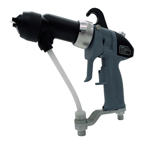
Page 21: R90/70 Cascade Solventborne Electrostatic Spray Applicator Features
INTRODUCTION Return To Contents Figure 1: R90/70 Cascade Solventborne Electrostatic Spray Applicator Features R90/70 CASCADE SOLVENTBORNE ELECTROSTATIC SPRAY APPLICATOR FEATURES Description Description Needle/Electrode Adjustable Trigger Shelf Barrel Fluid Hose Connection Replaceable Hook Low Voltage Cable Connection Fan Air Adjust Air Inlet Connection 2-Finger/4-Finger Trigger kV Setpoint Switch/Microamp Display AH-06-01-R17 (08/2019) -
Page 22: 80131-Xxx 9060 Power Supply Electrical Specifications
INTRODUCTION Return To Contents 80131-XXX 9060 POWER SUPPLY ELECTRICAL SPECIFICATIONS Electrical Input Voltage: 100-240 VAC Current: 1 A max. RMS Frequency: 50/60 Hz Wattage: 40 watts (max.) Output Voltage: 20-65 kV DC (79513-11X) 20-85 kV DC (79513-12X) Current: 100 microamps (max.) (79513-12X) 90 microamps (max.) (79513-11X) Physical Height:... -
Page 23: 80131-Xxx Cascade Control Unit Features
INTRODUCTION Return To Contents Figure 2: 80131-XXX Cascade Control Unit Features AH-06-01-R17 (08/2019) 23 / 79 www.carlisleft.com... -
Page 24: Installation
INSTALLATION Return To Contents INSTALLATION 79500 R90 SOLVENTBORNE WA R N I N G 79501 R70 SOLVENTBORNE † NEVER wrap the applicator, associated valves INSTALLATION and tubing, and supporting hardware in plastic to keep it clean. A surface charge may build up on the plastic surface and discharge to the nearest ground- WA R N I N G ed object. - Page 25 INSTALLATION Return To Contents R < 1 MEGOHM Figure 3: Typical Solventborne Installation Features TYPICAL SOLVENTBORNE INSTALLATION FEATURES Description Description Fluid Supply (Grounded) AC Line Cord (110/220) 9060 Control Unit Fluid Regulator Vector Applicator Air Line Ball Valve Low Voltage Cable Air Regulator W/Pressure Gauge Fluid Line Air/Water Separator...
-
Page 26: Low Voltage Cable
INSTALLATION Return To Contents The 9060 Control WA R N I N G Unit must be located a minimum of 5’ (1.5 m) outside of what is considered to be the hazardous area. Any mounting † The electrical discharge that is available from method used must properly support the unit to a minimum the charging electrode must not exceed 0.24 mJ of of 4X the unit weight. -
Page 27: Paint Preparation
INSTALLATION Air Hose Recommendation Prior to connecting the air hose to the low voltage unit and the fluid hose to the fluid supply, adjust the hose and low Ransburg recommends using a 79547-XX air hose assembly voltage cable position at the applicator to relieve some that may be ordered through your authorized Ransburg dis- strain on the low voltage cable. -
Page 28: Spray Pattern Adjustment
INSTALLATION SPRAY PATTERN ADJUSTMENT APPLICATOR TO TARGET DISTANCE The spray pattern of fan atomizers is adjustable from a small circle to an elongated oval, approximately 10-18-inches Hold the applicator 6-12-inches maximum from the target of usable pattern when sprayed from a target distance for best operation (higher transfer efficiency will be achieved of 8-12-inches. -
Page 29: Round Spray Performance Chart
INSTALLATION AIR CAP / FLUID NOZZLE SELECTION CHARTAIR SPRAY / TRANS-TECH. SPRAY Air Cap Part # Fluid Nozzle Part # Separate Retaining Ring Pressure Reducer Orifice ID 79374-65 79377-44 1.4mm (.055) 79379-00 74963-05 79374-65 79377-45 1.8mm (.070) 79379-00 74963-05 79374-98 79377-44 1.4mm (.055) 79379-00... -
Page 30: Operation
OPERATION Return To Contents OPERATION POWERING UP SETPOINT VOLTAGE CONTROL UNIT The Vector spray applicator system has three voltage set- points 1, 2, and 3. Each of these voltages can be individually When the AC power is turned on, the unit will display the PC adjusted between 20 and full kV using the + and - buttons board applicator type number on the kV setpoint display and on the front of the control unit. -
Page 31: Lockouts
OPERATION Return To Contents When a kV setpoint button is pressed, the light above the button will light and the kV display will show the present voltage for that setpoint. This indicates the unit is set to spray at that setpoint. To adjust the kV for the present setpoint, press the + or - setpoint adjust buttons. - Page 32 OPERATION Return To Contents Front Panel Lockout 1. Turn AC power off and access the interior of the control unit. This feature locks out any changes to the kV setting from the front panel of the control unit. 2. Place the jumper across the two (2) pins at location 15 on the main PC board (see Figure 10).
-
Page 33: Kv Test Jumper
OPERATION Return To Contents BASIC OPERATION Triggering High voltage is actuated by pulling the trigger to start the flow of atomizing and fan control air through the applicator. When the applicator is triggered, an air flow switch is ac- tivated, the kV setpoint is displayed on the kV display, the actual current draw on the µA display and the high voltage light illuminates. -
Page 34: Fault Descriptions
OPERATION Return To Contents To reset this register, press the reset button while the hours are displayed. Pressing the preset 2 and reset buttons at the same time will show the number of hours on the non-re-settable register. Local/Remote The Vector product line is designed currently for applicators only. -
Page 35: Maintenance
MAINTENANCE Return To Contents MAINTENANCE SUITABLE SOLVENTS FOR WA R N I N G CLEANING VECTOR R90/70 † The user MUST read and be familiar with the APPLICATORS safety instructions in this manual. When cleaning the applicator, a suitable solvent for cleaning †... -
Page 36: Routine Schedule
MAINTENANCE Return To Contents ROUTINE SCHEDULE CAUTION Follow these maintenance steps to extend the life of the † NEVER soak or submerge the electrical compo- applicator and ensure efficient oper-ation: nents of the applicator, i.e., barrel, hook, or cable. Damage and failure may occur. Several Times Daily •... -
Page 37: Applicator Assembly Cleaning Procedure
MAINTENANCE Return To Contents If the reading is outside of the acceptable range (95- CAUTION 100 µA for R90; 85-90 µA for R70), DO NOT use the applicator until the problem has been corrected (see † If the coating material is fast settling and the fluid "Troubleshooting Guide"... -
Page 38: Flushing Procedures
MAINTENANCE Return To Contents CAUTION CAUTION † When installing or removing the fluid nozzle, the † Metal tools and wire brushes must NEVER be applicator MUST be triggered. Failure to do so may used. NEVER use a cleaning tool that is harder than cause damage to the electrode or fluid nozzle. -
Page 39: Applicator Repair
MAINTENANCE Return To Contents APPLICATOR REPAIR WA R N I N G † Ensure the control unit power is OFF prior to any All repairs should be made on a clean, flat surface. If a maintenance. vise is used to hold parts during service or repair, DO NOT clamp onto plastic parts and always pad the vise jaws! Solventborne Applicators The following parts should be thoroughly packed with... -
Page 40: Air Cap
MAINTENANCE Return To Contents AIR CAP Removal 1. While holding the barrel with one hand, loosen the retaining nut using the other hand. 2. Unscrew the retaining nut completely and remove the air cap. Cleaning and Inspection 1. Use a suitable solvent to clean the air cap. (Refer to "Suitable Solvents for Cleaning Vector R90/70 Applicators"... -
Page 41: Needle / Electrode
MAINTENANCE Return To Contents 3 5 -4 0 L B S -I N 3 . 9 -4 . 5 N M Figure 19: Air Cap, Fluid Nozzle, and Nut AIR CAP, FLUID NOZZLE, AND NUT Item # Description Retaining Ring O-Ring, PTFE Encapsulated Air Cap Fluid Nozzle... -
Page 42: Needle / Electrode Resistance Testing
MAINTENANCE Return To Contents Cleaning and Inspection To Test 1. Use a suitable solvent to clean the needle/electrode. 1. Install the needle/electrode onto the front end of an available needle shaft. Be sure that the needle/electrode 2. Examine the needle/electrode for damage or wear. Pay is completely seated for proper contact between the special attention to the area where the wire electrode metal shaft and the threaded insert of the needle/... -
Page 43: Disassembly / Reassembly Of Barrel With The 2K Fluid Needle Packings
MAINTENANCE Return To Contents 4. Remove trigger from the applicator handle. 5. Using an adjustable wrench, unscrew the fluid tube connector from the barrel and slide it down the fluid tube. The fluid tube must be removed prior to removing the barrel to prevent damage to the cascade. - Page 44 MAINTENANCE Return To Contents 4. Remove the trigger adjustment nut if it was required Cleaning and Inspection when pulling the needle shaft from the barrel packing 1. Clean the packing chamber of the barrel with a suitable chamber. Then remove the packing nut, spacer, rear solvent and a soft bristle bottle brush.
- Page 45 MAINTENANCE Return To Contents CAUTION CAUTION † To avoid damage to the chevron seals, they † FAILURE to coat the needle shaft assembly MAY MUST be installed from the rear of the barrel. CAUSE lower electrical output of the applicator. Fill the inner diameter of the packing tube with dielectric 1.
- Page 46 MAINTENANCE Return To Contents 16. Pull the needle shaft rearward as far as it will go. WA R N I N G 17. Install the fluid nozzle, air cap, and retaining nut (refer † All six (6) spring washers MUST be replaced al- to "Air Cap"...
- Page 47 MAINTENANCE Return To Contents Attaching Barrel to Handle 1. If the barrel retaining nut has been removed, it will have to be reinstalled before the barrel can be attached to the handle. 2. Place the retaining nut over the rear of the barrel and slide it as far forward as possible.
-
Page 48: Handle / Plug Assembly
MAINTENANCE Return To Contents HANDLE / PLUG ASSEMBLY Removal 1. The following procedures must be performed prior to removing the handle: • Barrel removal • Low Voltage Cable removal • Fluid/Air Hose removal 2. Remove the gasket from the handle; if it was not removed with the barrel. - Page 49 MAINTENANCE Return To Contents 6. Remove the air inlet fitting and the fluid bracket from 8. Remove the trigger stop by turning the knob of the stop counter-clockwise until the thread of the stop is the base of the applicator. completely disengaged.
- Page 50 MAINTENANCE Return To Contents 4. Push the hook gasket into the groove of the hook. Apply a light coat of dielectric grease (LSCH0009) to the hook gasket exterior and slide the hook into position. Figure 39: Location of Handle Low Voltage Plug Recess Figure 38: Low Voltage Plug Locating Tab 5.
-
Page 51: Troubleshooting Guide
MAINTENANCE Return To Contents TROUBLESHOOTING GUIDE (Cont.) General Problem Possible Cause Solution DEFECTIVE SPRAY PATTERN Pattern Will Not Clogged or faulty fan air valve Clean, repair, or replace. Shape Air passages in applicator or air Blow out, clean, or replace. line clogged Worn, faulty, or clogged air cap Clean or replace. - Page 52 MAINTENANCE Return To Contents TROUBLESHOOTING GUIDE (Cont.) General Problem Possible Cause Solution LEAKAGE Clean and lubricate or replace. Defective valve seat or valve spring Fluid See “Barrel Assembly” in the Cartridge seal assembly and/or needle/ “Maintenance” section. (At rear of barrel) electrode shaft defective Fluid Tighten.
-
Page 53: Maintenance
MAINTENANCE Return To Contents TROUBLESHOOTING GUIDE (Cont.) General Problem Possible Cause Solution ELECTRICAL (Cont.) Improper or No High Blown fuse Replace fuse. Voltage (Cont.) Is the power turned on? Check power supply. Is the atomizing air turned on? Check air regulator. Is the applicator triggered? Check applicator trigger. -
Page 54: Parts Identification
PARTS IDENTIFICATION Return To Contents PARTS IDENTIFICATION Figure 40: R90/70 Cascade Solventborne Applicator Breakdown AH-06-01-R17 (08/2019) 54 / 79 www.carlisleft.com... - Page 55 PARTS IDENTIFICATION Return To Contents R90/70 CASCADE SOLVENTBORNE APPLICATOR - PARTS LIST (Figure 40) Description Item # Part # 79468-00 Barrel, Machined, R90 79469-00 Barrel, Machined, R70 79373-00 Nut, Retaining Barrel 75326-00 Ring, Retaining 79599-01 Needle Shaft Assembly, R90, 2k Packings (Std.) 79599-02 Needle Shaft Assembly, R70, 2k Packings (Std.) Table D-"D3"...
- Page 56 PARTS IDENTIFICATION Return To Contents R90/70 CASCADE SOLVENTBORNE APPLICATOR - PARTS LIST (Cont.) (Figure 40) Description Item # Part # 79385-00 Nut, Connector, Hose Table C-"C5" EMF-202-05 Ferrule, Back, 3/8" Tube Table C-"C5" EMF-203-05 Ferrule, Front, 3/8" Tube Table C-"C5" Table C-"C2"...
-
Page 57: Vector R90/70 Cascade Solventborne Model Identification
PARTS IDENTIFICATION Return To Contents VECTOR R90/R70 CASCADE SOLVENTBORNE MODEL IDENTIFICATION 79500/79501 - A 0 = Standard Spray, 65kV Air Cap, 1.4mm Fluid Nozzle, #44 1 = Standard Spray, 65kV Air Cap, 1.8mm Fluid Nozzle, #45 2 = Trans-Tech.. 122V Air Cap, 1.8mm Fluid Nozzle, #245 3 = Round Spray 0 = Applicator Only 1 = Domestic Sales, Complete W/ Power Supply 110/120... - Page 58 PARTS IDENTIFICATION Return To Contents TABLE C - FLUID DELIVERY COMBINATION Description "C" Dash # "C3" "C4" "C1" "C2" "C5" Offset Bracket, .093" ID Fluid Tube 79438-00 70399-00 10553-06 9704-16 Bracket, .093" ID Fluid Tube 70442-00 79439-00 10553-06 9704-16 ° Offset Bracket (SS), .093"...
-
Page 59: R90 (78628-11) And R70 (79599-02) Cascade Needle Shaft (Standard 2K Packings) / Parts List
PARTS IDENTIFICATION Return To Contents Figure 41: R90 (79599-01) and R70 (79599-02) Cascade Needle Shaft (2k Packings)-Standard R90 (79599-01) AND R70 (79599-02) CASCADE NEEDLE SHAFT (STANDARD 2K PACKINGS) - PARTS LIST (Figure 41) Part # Description Item # 78627-04 Shaft Assembly, 2-Piece Needle, R90, 2k Packings 78627-05 Shaft Assembly, 2-Piece Needle, R70, 2k Packings 74653-00... -
Page 60: R90 (79599-01) And R70 (79599-02) Cascade Needle Shaft Parts List
PARTS IDENTIFICATION Return To Contents Figure 42: R90 (78628-11) and R70 (78628-12) Cascade Needle Shaft (Optional Packings) R90 (78628-11) AND R70 (78628-12) CASCADE NEEDLE SHAFT (OPTIONAL PACKINGS) - PARTS LIST (Figure 42) Item # Part # Description 70430-01 Electrode, High Flex 78626-00 Seal Cartridge Non-Adj., Assembly 78627-04... -
Page 61: Waterborne Applicator Model 79523 Section
PARTS IDENTIFICATION Return To Contents WATERBORNE APPLICATOR MODEL 79523-XXXXX SECTION WA R N I N G † Typical installations to spray non-flammable conductive materials (waterborne materials) must not be used to handle flammable materi- als (solvent based materials). AH-06-01-R17 (08/2019) 61 / 79 www.carlisleft.com... -
Page 62: R90 Cascade Waterborne Electrostatic Spray Applicator Features
PARTS IDENTIFICATION Return To Contents Figure 43: R90 Cascade Waterborne Electrostatic Spray Applicator Features R90 CASCADE WATERBORNE ELECTROSTATIC SPRAY APPLICATOR FEATURES (Figure 43) Description Description Needle/Electrode Waterborne Hose Barrel Low Voltage Cable Connection Replaceable Hook Air Hose Connection Fan Air Adjust kV Setpoint Switch/Microamp 11 Display 2-Finger/4-Finger Trigger Waterborne Source Connection... -
Page 63: 79523 R90 Cascade Waterborne Specifications
PARTS IDENTIFICATION Return To Contents 79523 R90 CASCADE WATERBORNE SPECIFICATIONS Environmental/Physical Gun Length: 27cm (10.7 inches) Weight: 735 grams (25.9 oz.) Hose & Cable Lengths (Std): 10m, 15m, 20m, 25m, and 30m Atomizer Nozzle Assembly (Std): 79374-65, 79377-45 Electrical Operating Voltage: 85 kV DC (-) maximum Current Output: 100 microamperes maximum... - Page 64 PARTS IDENTIFICATION Return To Contents CONTROL UNIT INPUTS / OUTPUTS 9050 Part # Voltage Designation Maximum Output 79513-121 110/120 VAC -85 kV DC 79513-122 220/240 VAC -85 kV DC CONTROL UNIT / APPLICATOR COMBINATIONS For Use With Applicator Combinations 9050 Part # 79513-12X 79523-XXXXX AH-06-01-R17 (08/2019)
-
Page 65: R90 Cascade Waterborne Typical Installation
PARTS IDENTIFICATION Return To Contents R <1 M E G O H M Figure 44: R90 Cascade Waterborne Typical Installation R90 CASCADE WATERBORNE TYPICAL INSTALLATION Description Description AC Line Cord (110/220) Fluid Regulator 9060 Power Supply Air Line Vector Applicator Low Voltage Cable Ball Valve Fluid Valve... -
Page 66: Waterborne Isolation System Installation Guidelines
PARTS IDENTIFICATION Return To Contents WA R N I N G • Air regulators for pots or pumps should be mounted remotely outside the fence or cage area to facilitate † Typical installations to spray non-flammable changes in pressure without shutting the system down. conductive materials (waterborne materials) must not be used to handle flammable materials (solvent •... - Page 67 PARTS IDENTIFICATION Return To Contents WA R N I N G † Special care must be taken when removing the sheathing from the fluid hose. Make sure all tools are very sharp and only score the surface of the sheath. Inserting the knife too deep can score the surface of the core material and lead to pin-holing and failure of the hose.
-
Page 68: Waterborne Fluid Delivery Components / Parts List
PARTS IDENTIFICATION Return To Contents Figure 45: Waterborne Fluid Delivery Components AH-06-01-R17 (08/2019) 68 / 79 www.carlisleft.com... - Page 69 PARTS IDENTIFICATION Return To Contents WATERBORNE FLUID DELIVERY COMPONENTS - PARTS LIST (Figure 45) Part # Description Item # Table F - "F" Fluid Hose, Assembly, Vector * 74179-XX Bulk Tube, Fluid, 1/4" ID 72307-XX Bulk Tube, Fluid, 3/16" ID 72310-00 Connector, Bulk Head 10553-05...
-
Page 70: Vector R90 Cascade Waterborne Model Identifications
PARTS IDENTIFICATION Return To Contents VECTOR R90 CASCADE WATERBORNE MODEL IDENTIFICATION 79500/79501 - A 0 = Applicator Only 1 = Domestic Sales, Complete W/ Power Supply 110/120 2 = Export Sales, Complete W/ Power Supply 240V, -50/60Hz 0 = Standard Spray, 65kV Air Cap, 1.4mm Fluid Nozzle, #44 1 = Standard Spray, 65kV Air Cap, 1.8mm Fluid Nozzle, #45 2 = Trans-Tech.. -
Page 71: Vector Air Hose Options / Parts List
PARTS IDENTIFICATION Return To Contents Figure 46: Optional Air Hose VECTOR AIR HOSE OPTIONS - PARTS LIST (Figure 46) Item # Part # Description 79547-10 Air Hose Assembly, 10m (33') 79547-15 Air Hose Assembly, 15m (49') 79547-20 Air Hose Assembly, 20m (66') 79547-31 Air Hose Assembly, 30m (99') LSFI0027... -
Page 72: Vector Applicator Cover Options / Parts List
PARTS IDENTIFICATION Return To Contents Figure 48: Applicator Cover VECTOR APPLICATOR COVER OPTIONS - PARTS LIST Item # Part # Description 79529-00 Applicator Cover 79529-00-K5 Applicator Cover, Package of 5 Figure 49 - Swirl Nozzle VECTOR SWIRL NOZZLE OPTIONS - PARTS LIST Part # Description Item #... -
Page 73: Vector Fluid Tube Options / Parts List
PARTS IDENTIFICATION Return To Contents Figure 50: Fluid Tube VECTOR FLUID TUBE OPTIONS Qty. Part # Description See "Item 36" 9704-16 .093" ID Tube (Standard W/Applicator) .125" ID Tube See "Item 36" 9704-05 .250" ID Tube See "Item 36" 9704-11 NOTE: The standard fluid delivery tube is the smallest diameter to work best with highly conductive materials, down to .1 megohm resistance. -
Page 74: Parts Comparison / Trans-Tech Atomization / Parts List
PARTS IDENTIFICATION Return To Contents PARTS COMPARISON 79374-65 Standard Air Spray Air Cap 79374-122 Trans-Tech. Air Spray Air Cap Standard Air Spray Nozzles have a number between 44 and 148; Trans-Tech. Air Spray Nozzles have a number between 244 and 348. Standard Air Spray Nozzles have a longer, narrower tip;... -
Page 75: 79555 Trans-Tech Conversion Kits Available
PARTS IDENTIFICATION Return To Contents 79555 TRANS-TECH. CONVERSION KITS AVAILABLE Description Kit Part No. Fluid Nozzle Part No. 79552-244 1.4mm (.055") Acetal 79555-244 79552-245 1.8mm (.070") Acetal 79555-245 79552-247 0.7mm (.028") Acetal 79555-247 79552-344 1.4mm (.055") Peek 79555-344 79552-345 1.8mm (.070") Peek 79555-345 79552-347 0.7mm (.028") Peek... -
Page 76: Vector Cascade Applicators Recommended Spare Parts
PARTS IDENTIFICATION Return To Contents VECTOR CASCADE APPLICATORS RECOMMENDED SPARE PARTS Part # Description 10051-05 Cup Seal, Spring Loaded 17130-00 Spring, Return 19749-00 Applicator Wrench Accessory 3587-02 Nut and Ferrule 3587-03 Nut and Ferrule 59972-00 Dielectric Grease Accessory 70430-01 Electrode High Flex 75326-00 Barret Retaining Ring 78626-00... -
Page 77: Parts Identification
PARTS IDENTIFICATION Return To Contents VECTOR CASCADE APPLICATORS RECOMMENDED SPARE PARTS (Cont.) Part # Description 79454-00 Trigger Retaining Screws 79460-03 Plug Assembly 79468-00 Barrel, R90 Cascade 79468-00 Barrel, R70 Cascade 79471-01 Rear Cover W/Switch 79479-00 Applicator Hook Seal 79529-00-K5 Applicator Covers Accessory 79560-00 Trigger Stop Assembly... -
Page 78: Manual Change Summary
MANUAL CHANGES Return To Contents MANUAL CHANGE SUMMARY AH-06-01-R17 - Replaces AH-06-01.16 with the folowing changes: Change Description Page(s) Update to latest manual format. Change page head to new verbage. Change text in bullet point number two under “To Test” AH-06-01-R17 (08/2019) 78 / 79 www.carlisleft.com... - Page 79 This product is covered by Carlisle Fluid Technologies materials and workmanship limited warranty. The use of any parts or accessories, from a source other than Carlisle Fluid Technologies, will void all warranties. For specific warranty information please contact Carlisle Fluid Technologies.
Need help?
Do you have a question about the Ransburg Vector R70 Cascade and is the answer not in the manual?
Questions and answers