Table of Contents
Advertisement
Quick Links
Advertisement
Table of Contents

Subscribe to Our Youtube Channel
Related Manuals for Meinberg IMS-GPS183


Summary of Contents for Meinberg IMS-GPS183
- Page 1 SETUP GUIDE IMS-GPS183 Hot-Plug Module Meinberg Funkuhren GmbH & Co. KG...
-
Page 3: Table Of Contents
8 IMS-GPS183 Models 9 IMS-GPS183 Module Connectors and LEDs Status LEDs .......... - Page 4 15 Technical Appendix 15.1 Technical Specifications: IMS-GPS183 Module ......15.2 Technical Specifications: GPSANTv2 Antenna ......
-
Page 5: Imprint And Legal Information
1 Imprint and Legal Information 1 Imprint and Legal Information Publisher Meinberg Funkuhren GmbH & Co. KG Registered Place of Business: Lange Wand 9 31812 Bad Pyrmont Germany Telephone: +49 (0) 52 81 – 93 09 - 0 Fax: +49 (0) 52 81 – 93 09 - 230 The company is registered in the "A"... -
Page 6: Copyright And Liability Exclusion
Meinberg reserves the right to make changes of any type to this document at any time as is necessary for the purpose of improving its products and services and ensuring compliance with applicable standards, laws &... -
Page 7: Change Log
New link system for internal references and external links Chapter 4, “Presentation Conventions in this Manual” Expanded Chapter 7, “Introduction” Restructured Chapter 8, “IMS-GPS183 Models” Restructured Status LEDs Chapter 9.1, “Status LEDs” Restructured serial interface Chapter 9.2, “COMx Time String I/O and Pulse-Per-Second Input”... -
Page 8: Presentation Conventions In This Manual
4 Presentation Conventions in this Manual 4.1 Conventions for the Presentation of Critical Safety Warnings Warnings are indicated with the following warning boxes, using the following signal words, colors, and symbols: Caution! This signal word indicates a hazard with a low risk level. Such a notice refers to a procedure or other action that may result in minor injury if not observed or if improperly performed. -
Page 9: Secondary Symbols Used In Safety Warnings
4 Presentation Conventions in this Manual 4.2 Secondary Symbols Used in Safety Warnings Some warning boxes may feature a secondary symbol that emphasizes the defining nature of a hazard or risk. The presence of an "electrical hazard" symbol is indicative of a risk of electric shock or lightning strike. -
Page 10: Generally Applicable Symbols
4.4 Generally Applicable Symbols The following symbols and pictograms are also used in a broader context in this manual and on the product. The presence of the "ESD" symbol is indicative of a risk of product damage caused by electrostatic discharge. Direct Current (DC) (symbol definition IEC 60417-5031) Alternating Current (AC) (symbol definition IEC 60417-5032) Grounding Terminal (symbol definition IEC 60417-5017) -
Page 11: Important Safety Information
Depending on your specific device configuration and installed options, some safety information may not be applicable to your device. Meinberg accepts no responsibility for injury or death arising from a failure to observe the safety information, warnings, and safety-critical instructions provided in the product documentation. -
Page 12: Product Documentation
If any of the safety information in the product documentation is unclear for you, do not continue with the set-up or operation of the device! Safety standards and regulations change on a regular basis and Meinberg updates the corresponding safety information and warnings to reflect these changes. It is therefore recommended to regularly visit the Meinberg website at https://www.meinbergglobal.com... -
Page 13: Safety During Installation
Never drill holes into the device to mount it! If you are experiencing difficulties with rack installation, contact Meinberg’s Technical Support team for assistance! Inspect the device housing before installation. The device housing must be free of any damage when it is installed. -
Page 14: Battery Safety
5.4 Battery Safety The integrated CR2032 lithium battery has a service life of at least ten years. Should it be necessary to replace the battery, please note the following: • The battery may only be replaced by the same type or a comparable type recommended by the manufacturer. -
Page 15: Important Product Information
6 Important Product Information 6 Important Product Information 6.1 CE Marking This product bears the CE mark as is required to introduce the product into the EU Single Market. The use of this mark is a declaration that the product is compliant with all requirements of the EU directives effective and applicable as at the time of manufacture of the product. -
Page 16: Maintenance And Modifications
6.4 Maintenance and Modifications Important! Before performing any maintenance work on or authorized modification to your Meinberg system, we recommend making a backup of any stored configuration data (e.g., to a USB flash drive from the Web Interface). 6.4.1 Replacing the Battery Your device’s clock module is fitted with a lithium battery (type CR2032) that is used to locally storage almanac... -
Page 17: Prevention Of Esd Damage
6 Important Product Information 6.5 Prevention of ESD Damage An ESDS device (electrostatic discharge-sensitive device) is any device at risk of dam- age or malfunction due to electrostatic discharge (ESD) and thus requires special mea- sures to prevent such damage or malfunction. Systems and modules with ESDS compo- nents usually bear this symbol. -
Page 18: Disposal
It can be returned to Meinberg for disposal. Any transportation expenses for returning this product (at end-of- life) must be covered by the end user, while Meinberg will bear the costs for the waste disposal itself. If you wish for Meinberg to handle disposal for you, please get in touch with us. Otherwise, please use the return and collection systems provided within your country to ensure that your device is disposed of in a compliant fashion to protect the environment and conserve valuable resources. -
Page 19: Introduction
The IMS-GPS183’s receiver determines its position using at least four visible GNSS satellites. This position is used to calculate an offset for the timing data received from the GNSS satellites. Once the IMS-GPS183 is successfully synchronized with a suitable reference, it generates a PPS (pulse-per-second) phase reference and a 10 MHz frequency reference. - Page 20 This version of the manual has been prepared based on the feature set provided by Firmware Version 1.15 of your IMS-GPS183 as well as LANTIME OS Version 7.08. When using a LANTIME system or IMS module with different versions, there may be noticeable differences, for example in the presentation and availability of options in the Web Interface as shown in Chapter 13, “Initial...
- Page 21 This brief Setup Guide only provides the information required to quickly set up your module in your IMS system with a minimum of problems. We recommend also carefully studying the following manuals alongside this Setup Guide for the use of your IMS-GPS183: Meinberg IMS System Manuals (all systems) http://www.mbg.link/doc-en...
-
Page 22: Ims-Gps183 Models
Installing an IMS-GPS183 module with a two-slot faceplate in an M500, M1000, or M1000S IMS system will result in the adjacent slot (I/O, MRI, or Clock) being obscured and thus unavailable for another IMS module. Please note this when ordering a new IMS system or additional modules for your IMS system. -
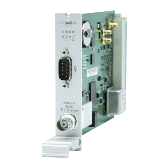
Page 23: Ims-Gps183 Module Connectors And Leds
9 IMS-GPS183 Module Connectors and LEDs 9 IMS-GPS183 Module Connectors and LEDs Information: The numbering in the drawing above relates to the relevant subsection in this chapter. Date: August 21, 2024... -
Page 24: Status Leds
9.1 Status LEDs Init" LED: Initialization status of reference clock "Nav" LED: Navigation data (position/time) is available "Ant" LED: Antenna status "Fail" LED: Lack of available reference sources Colors Description Init Blue The internal firmware is initializing and a connection is being established with the LANTIME system. -
Page 25: Comx Time String I/O And Pulse-Per-Second Input
Refer to Chapter 13.2, “Synchronization with Time String and PPS” for more information on using PPS & time string inputs to synchronize your IMS-GPS183. Data Transfer Mode: Serial I/O 19200 (Default), 9600, 4800, 2400, 1200,... -
Page 26: Antenna Input: Gps Receiver
9.3 Antenna Input: GPS Receiver Danger! Do not work on the antenna installation during thunderstorms! Danger of death from electric shock! • Do not carry out any work on the antenna installation or the antenna cable if there is a risk of lightning strike. -
Page 27: Xhe-Spi Connector
9 IMS-GPS183 Module Connectors and LEDs 9.4 XHE-SPI Connector Important! This connector must only be used to connect a Meinberg IMS-XHE Rubidium expansion chassis. The use of this port to connect other devices is not supported and may invalidate the warranty of your LANTIME system and your IMS-GPS183 module. -
Page 28: Before You Start
10.1 Contents of Delivery Unpack the IMS-GPS183 and all accessories carefully and check the contents of the delivery against the en- closed packing list to ensure that no parts are missing. If any of the listed items are missing, please contact our Sales Department at sales@meinberg.de. -
Page 29: Installing A Gps Antenna
11.1 Selecting the Antenna Location There are essentially two ways a compatible Meinberg GPS Antenna (such as a GPSANTv2) can be installed using the accessories included: 1. Mounted on a pole 2. - Page 30 55 south parallels (satellite orbits). Information: Problems may arise with the synchronization of your Meinberg time server if these conditions are not met, as four satellites must be located to calculate the exact position. Date: August 21, 2024...
-
Page 31: Installation Of The Antenna
11 Installing a GPS Antenna 11.2 Installation of the Antenna Please read the following safety information carefully before installing the antenna and ensure that it is ob- served during the installation. Danger! Do not mount the antenna without an effective fall arrester! Danger of death from falling! •... - Page 32 Mount the Meinberg GPS Antenna (as shown in Fig. 3) at a distance of at least 50 cm to other antennas using the mounting kit provided, either onto a vertical pole of no more than 60 mm diameter or directly onto a wall.
-
Page 33: Antenna Cable
Meinberg provides suitable cable types with its antennas and these are ordered together with the antenna to match the length you need from your antenna to your Meinberg reference clock. The route to be covered for your antenna installation should be determined and the appropriate cable type selected accordingly before confirming your order. - Page 34 Laying the Antenna Cable When laying the antenna cable, ensure that the specified maximum cable length is not exceeded. This length will depend on the selected cable type and its attenuation factor. If the specified maximum length is exceeded, correct transmission of the synchronization data and thus proper synchronization of the reference clock can no longer be guaranteed.
-
Page 35: Surge Protection And Grounding
Please refer to the standards regarding antenna installations (e.g., DIN EN 60728-11) for more information. However, in order to preserve the safety of the building and to protect your Meinberg system, Meinberg recommends the use of the MBG-S-PRO surge protector, which is addressed in more detail later in this chap- ter. - Page 36 Electrical Bonding Electrical bonding is the connection of all metallic, electrically conductive elements of the antenna instal- lation in order to limit the risk of dangerous voltages for people and connected devices. To this end, the following elements should be connected and integrated into a bonding system: •...
- Page 37 11 Installing a GPS Antenna The following drawings illustrate how a Meinberg GPS Antenna can be installed in accordance with the above conditions on a pole (e.g., antenna pole) or building roof. Antenna Installation without Insulated Lightning Rod System α...
- Page 38 Antenna Installation with Insulated Lightning Rod System α Fig. 6: Roof Installation Meinberg GPS Antenna Lightning Rod Lightning Rod Conductor Antenna Cable Bonding Conductor Bonding Bar Foundation Electrode Safety Zone Date: August 21, 2024...
- Page 39 11 Installing a GPS Antenna Optional MBG S-PRO Surge Protector Information: The surge protector and suitable coaxial cable are not included as standard with a Meinberg GPS Antenna, but can be ordered as an optional accessory. Construction The MBG-S-PRO is a surge protector (Phoenix CN-UB-280DC-BB) for coaxial connections. It is patched directly into the antenna line and consists of a replaceable gas discharge tube that redirects the energy from the cable shielding to the ground potential when ignited.
- Page 40 Meinberg system in order to prevent destructive potential differences. Connect the coaxial cable from the antenna to one of the surge protector connectors, then connect the other surge protector connector to the coaxial cable leading to the Meinberg reference clock. Caution!
-
Page 41: System Installation
12 System Installation 12 System Installation 12.1 Important Information Regarding Hot-Pluggable IMS Modules The following information should be strictly observed when replacing IMS modules during operation. Not all IMS modules are fully hot-pluggable. For example, it is naturally not possible to replace a power supply unit in a system without PSU redundancy without first having installed a second power supply unit while the system is in operation. -
Page 42: Installation And Removal Of Hot-Pluggable Ims Modules
12.2 Installation and Removal of Hot-Pluggable IMS Modules A Torx screwdriver is required (T8 x 60) to remove and install IMS modules. Important! Heed the “Important Safety Information” Chapter 5 of this manual! Removing a Module Remove the two marked Torx screws from the module faceplate. - Page 43 12 System Installation Installing a Module To replace a module, remove the installed module in accordance with the guide "Removing a Module” on the previous page. Otherwise, remove the two Torx screws from the cover plate of the unused slot. We recommend keeping the cover plate in a safe place for later use. Insert the module correctly into the two guide rails of the system chassis.
-
Page 44: Data And Signal Cables
Please note that the pin layout of the device receiving the time string output will dictate whether you require a "straight-through" or a null modem cable to connect your IMS-GPS183 module to a time string receiver. A null modem cable has Pins 2 and 3 ’crossed over’, so that Pin 2 at one end leads to Pin 3 at the other, and vice versa. -
Page 45: Initial Setup
13 Initial Setup This chapter explains how to set up and monitor the IMS-GPS183 via the Web Interface. The IMS-GPS183 can be set up to be synchronized to a GNSS reference, to an external time string + PPS source, and/or to another external source such as an IMS-MRI, IMS-ESI, or IMS-HPS100 input module. -
Page 46: Synchronization With Gnss
(from antenna to Meinberg system) in order to have the system calculate a plausible estimate of the delay. In the case of the IMS-GPS183, the system will assume that 5 nanoseconds of propagation delay is incurred per meter of antenna cable and assumes that you are using RG 58 C/U coaxial cable. - Page 47 13 Initial Setup You can enter the measured or calculated propagation delay or the length of your cable as follows: From the same page as Step 1 above (Clock –> State and Configuration), ensure that the "Miscellaneous" tab under the corresponding clock module is selected.
- Page 48 Final Steps Once the antenna and power supply have been connected, the reference clock is ready for operation. After around two minutes of the system being switched on, the oscillator will have warmed up and thus achieved the base precision required to receive satellite signals. If valid almanac and ephemeris data are present in the reference clock’s battery-backed memory and the receiver’s position has not changed since it was last on, the system’s CPU will be able to calculate which satellites should currently be receivable.
-
Page 49: Synchronization With Time String And Pps
& pulse-per-second reference. Step 1: Connection of the IMS-GPS183 with the PPS & Time String Sources Ensure that the IMS-GPS183 is connected to both an external PPS phase reference and a valid time string source as described in Chapter 9.2, “COMx Time String I/O and Pulse-Per-Second... - Page 50 Step 2: Time String Configuration Illustration: Serial Port Settings of your IMS-GPS183 From the LTOS Web Interface, open the "Clock" page and select the "State & Configuration" panel. Open the tab "Serial Ports" under the corresponding clock. Please note that the time string format under the "Serial Ports" tab relates to string output only; the for- mat of the incoming time string signal will be identified automatically by the system and does not need to be...
-
Page 51: Synchronization Via Another Ims Input Module
IMS-ESI module (allowing arbitrary frequency or T1/E1 clock signal inputs), or an IMS-VSI module (allowing clock signals typically used in the broadcasting industry to be used as reference signals). Please refer to the Setup Guides for those modules for more information on how to configure your IMS-GPS183 for use with those input modules. -
Page 52: Troubleshooting
Our Technical Support team will be pleased to help you with any problems that you may be having with your Meinberg IMS-GPS183 module. However, before you contact our Technical Support team, it is advisable to read this chapter through first to see if your problem might be more quickly resolved with one of the solutions below. - Page 53 14 Troubleshooting The reference clock’s precision If the position of the antenna is Ensure that the location of the is poor and/or synchronization poorly selected, the reference antenna is selected in accordance is frequently lost. clock will lose track of the with the conditions specified in satellites that have been Chapter...
-
Page 54: Technical Appendix
15 Technical Appendix 15.1 Technical Specifications: IMS-GPS183 Module Electrical Connector: 96-Pin IEC 60603-2 (DIN 41612) Connector Operating Voltage: +5 V DC Current Draw: Approx. 1.3 A (OCXO SQ oscillator, other oscillators may draw higher current) Power Consumption: Approx. 6.5 W (OCXO SQ oscillator, other oscillators may draw... -
Page 55: Technical Specifications: Gpsantv2 Antenna
15 Technical Appendix 15.2 Technical Specifications: GPSANTv2 Antenna Physical Dimensions Date: August 21, 2024... - Page 56 Specifications Power Supply: 15 V, approx. 100 mA (provided via antenna cable) Reception Frequency: 1575.42 MHz (GPS L1/Galileo E1 Band) Bandwidth: 9 MHz Frequencies: Mixing Frequency: 10 MHz Intermediate Frequency: 35.4 MHz Element Gain: Typically 5.0 dBic at zenith Polarization: Right-Hand Circular Polarization Axial Ratio: 3 dB at zenith...
-
Page 57: Technical Specifications: Mbg-S-Pro Surge Protector
15 Technical Appendix 15.3 Technical Specifications: MBG-S-PRO Surge Protector The MBG-S-PRO is a surge protector (Phoenix CN-UB-280DC-BB) for coaxial connections. It is patched directly into the antenna line and consists of a replaceable gas discharge tube that redirects the energy from the cable shielding to the ground potential when ignited. -
Page 58: Technical Specifications: Oscillators
15.4 Technical Specifications: Oscillators TCXO OCXO-LQ OCXO-SQ OCXO-HQ OCXO-DHQ Short-Term Stability 2 × 10⁹ 1 × 10⁹ 5 × 10¹⁰ 5 × 10¹² 2 × 10¹² (where t = 1 second) Pulse-per-Second < ± 100 ns < ± 100 ns <... -
Page 59: Technical Specifications: Ims Module Interface
15 Technical Appendix 15.5 Technical Specifications: IMS Module Interface Row A Row B Row C V in (+5 V) V in (+5 V) V in (+5 V) V in (+12 V) V in (+12 V) V in (+12 V) in (TCXO/OCXO) in (TCXO/OCXO) in (TCXO/OCXO) Reserved (FreqAdjust Out) -
Page 60: Mrs Functionality
15.6 MRS Functionality When the system is powered up or rebooted, the oscillator will initially run solely off the internal oscillator ("free-run mode"). As soon as one of the available reference sources has been synchronized and validated, there will be an initial "hard" adjustment of the internal time (main oscillator). The oscillator from that point will then only be adjusted in very small steps. - Page 61 15 Technical Appendix Precision This parameter dictates the fundamental accuracy of this reference source. When switching between differ- ent time sources, this value and the accuracy of the oscillator is used to calculate the holdover time, which is the delay until the actual changeover. If the "precision" value is zero, the system will switch to the next reference clock in the order of priority immediately.
-
Page 62: How Satellite Navigation Works
15.7 How Satellite Navigation Works The use of a receiver for location tracking and time synchronization relies on the ability to measure the satellite- to-receiver propagation delay as precisely as possible. It is necessary to have simultaneous reception from at least four satellites so that the receiver can determine its relative spatial position in three dimensions (x, y, z) and measure the deviation of its clock against the system clock. -
Page 63: Your Opinion Matters To Us
16 Your Opinion Matters to Us 16 Your Opinion Matters to Us This user manual is intended to assist you in the preparation, use, and care of your Meinberg product, and provides important information for configuration and status monitoring. Be a part of the ongoing improvement of the information contained in this manual. Please contact our Technical Support team if you have any suggestions for improvements or technical questions that are relevant to the manual. -
Page 64: Rohs Conformity
17 RoHS Conformity Conformity with EU Directive 2011/65/EU (RoHS) We hereby declare that this product is compliant with the European Union Directive 2011/65/EU and its delegated directive 2015/863/EU "Restrictions of Haz- ardous Substances in Electrical and Electronic Equip- ment" and that no impermissible substances are present in our products pursuant to these Directives. -
Page 65: List Of Abbreviations
18 List of Abbreviations 18 List of Abbreviations Bayonet Neill–Concelman Connector Clock Central Processing Unit Direct Current D-Sub D-Subminiature Electrostatic Discharge ESDS Electrostatic Discharge Sensitivity/Sensitive External Synchronization Input Ground GNSS Global Navigation Satellite System Global Positioning System Horizontal Pitch Intelligent Modular Synchronization Input/Output LTOS LANTIME Operating System...
Need help?
Do you have a question about the IMS-GPS183 and is the answer not in the manual?
Questions and answers