
Related Manuals for Meinberg IMS-RSC180


Summary of Contents for Meinberg IMS-RSC180
- Page 1 SETUP GUIDE IMS-RSC180 Hot-Plug Module December 17, 2021 Meinberg Funkuhren GmbH & Co. KG...
-
Page 3: Table Of Contents
RSC Switch Card: Monitoring and Mangement ......6.3.1 Configuration Using IMS-RSC180 via Web Interface ..... . 6.3.2 Configuration Using RSC/MDU and Meinberg Device Manager . -
Page 4: Imprint
1 Imprint 1 Imprint Meinberg Funkuhren GmbH & Co. KG Lange Wand 9, 31812 Bad Pyrmont, Germany Phone: + 49 (0) 52 81 / 93 09 - 0 Fax: + 49 (0) 52 81 / 93 09 - 230 Website: https://www.meinbergglobal.com... -
Page 5: Introduction
2 Introduction This Setup Guide is a systematically structured guideline to assist you with the set-up of your Meinberg product. Functionality of IMS-RSC180 The RSC Redundant Switch Control module controls the switchover mechanism between two reference clocks in redundant systems with two Meinberg clock modules. The RSC is used to switch between the connected clocks and to select the corresponding pulse, frequency outputs, and serial interfaces. -
Page 6: Important Safety Information
This manual is only intended to be used by qualified electricians, or by persons who have been appropriately instructed by qualified electricians and who are familiar with applicable national standards and safety rules & regulations, especially in relation to the installation of low-voltage (< 1000 V) installations. IMS-RSC180 Date: December 17, 2021... -
Page 7: Prevention Of Esd Damage
ESD-proof bags that are crumpled or have holes cannot provide effective protection against electrostatic discharges. ESD-proof bags must have a sufficient electrical resistance and must not be made of conductive metals if the device has a lithium battery fitted on it. Date: December 17, 2021 IMS-RSC180... -
Page 8: Power Supply
In the event that a power supply unit is no longer working (e.g. defective), please return it to Meinberg for repair. Failure to observe these safety instructions may result in serious injury and/or property damage. The IMS system must only be installed, set up, and operated by qualified personnel. -
Page 9: Leds, Switches, And Interfaces On The Ims-Rsc180
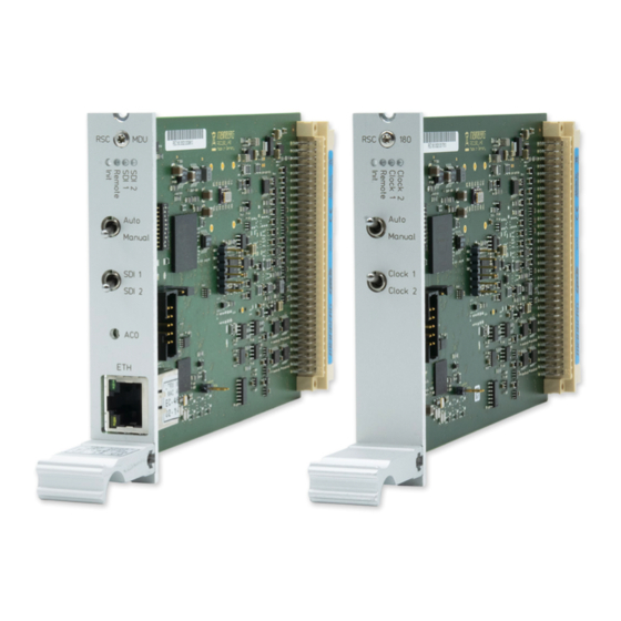
4 LEDs, Switches, and Interfaces on the IMS-RSC180 RSC180/MDU RSC180 1. LED Indicator Clock 1 / Clock 2 (SDI 1 / SDI 2) These LEDs show which of the two reference clocks is currently the "Master Clock". Remote This indicates whether the module is currently being managed remotely over an Ethernet connection. In remote mode, the Master Clock can be selected using an SNMP command. - Page 10 4 LEDs, Switches, and Interfaces on the IMS-RSC180 2. Auto/Manual Switch This switch selects between Automatic and Manual mode. Manual mode overrides the module’s internal selec- tion logic and the reference clock used for signal generation can only be selected manually using the Clock 1 / Clock 2 switch.
- Page 11 The button labeled ACO can be used if the access password has been forgotten. However, it will only work if there is no connection with the "Meinberg Device Manager" software. If it is held down for a short time (for around four seconds), the set password will be reset for 30 seconds to a blank field (i.e., you can simply press...
-
Page 12: Rsc180: Dip Switches
4 LEDs, Switches, and Interfaces on the IMS-RSC180 4.1 RSC180: DIP Switches The various modes of the board can also be configured using onboard DIP switches. Configuration Using DIP Switches NAME Description ———————————————————————————————————————— DIS_ENA Enables / disables signals if both clocks are out of sync... - Page 13 The "Priority Master" is Clock 2. If Switch 1 is ON: Switch 10 Positions: OFF: One clock is always enabled, even if out of sync. A clock is only enabled after the first sync event following a reset. Date: December 17, 2021 IMS-RSC180...
-
Page 14: Before You Start
5.1 Contents of Delivery Unpack the IMS-RSC180 carefully and check the contents of the delivery against the enclosed packing list to ensure that no parts are missing. If any of the listed items are missing, please contact our sales department: sales@meinberg.de... -
Page 15: System Installation
Operating System, the configuration of some IMS modules may be reset to factory defaults! The NTP service and access to the web interface will be unavailable while the CPU is not installed. Management and monitoring functions will also be disabled. Date: December 17, 2021 IMS-RSC180... -
Page 16: Installation Of Hot-Pluggable Ims Modules
Ensure that the module is securely seated in the connector block inside the chassis before you fasten the two screws. The installed module is now ready for use. Locations of fixture screws in a 1RU IMS system IMS-RSC180 Date: December 17, 2021... -
Page 17: Rsc Switch Card: Monitoring And Mangement
6.3 RSC Switch Card: Monitoring and Mangement 6.3.1 Configuration Using IMS-RSC180 via Web Interface The following parameters are configured via the RSC module when using two receiver modules (redundant mode). IRIG Settings: Selection of the desired time code (output). Programmable Pulses: Configuration of the Programmable Pulse Outputs (PPO_1 - PPO_4). -
Page 18: Configuration Using Rsc/Mdu And Meinberg Device Manager
"Remote-Controlled" here. This enables the Master Clock to be selected via the Meinberg Device Manager software. Please refer to the Meinberg Device Manager manual for a detailed overview and description of all con- figuration and monitoring options: https://www.meinbergglobal.com/download/docs/manuals/english/meinberg-device-manager.pdf... -
Page 19: Your Opinion Matters To Us
7 Your Opinion Matters to Us This user manual is intended to assist you in the preparation, use, and care of your Meinberg product, and provides important information for configuration and status monitoring. Be a part of the ongoing improvement of the information contained in this manual. Please contact our Technical Support team if you have any suggestions for improvements or technical questions that are relevant to the manual. -
Page 20: Rohs And Weee
WEEE-compliant fashion, it must be returned to the manufacturer. Any transportation ex- penses for returning this product (at end-of-life) must be covered by the end user, while Meinberg will bear the costs for the waste disposal itself. IMS-RSC180...
Need help?
Do you have a question about the IMS-RSC180 and is the answer not in the manual?
Questions and answers